Article

Effect of Applied Cathodic Potential on Friction and Wear Behavior of CoCrMo Alloy in NaCl Solution

School of Engineering and Sustainable Development, Faculty of Computing, Engineering and Media, De Montfort University, Leicester LE1 9BH, UK
*
Author to whom correspondence should be addressed.
Lubricants 2020, 8(11), 101; https://doi.org/10.3390/lubricants8110101
Submission received: 23 October 2020 / Revised: 18 November 2020 / Accepted: 19 November 2020 / Published: 23 November 2020

Abstract

:
Most of the reported work on the effect of applied potential on tribocorrosion or corrosive wear of metallic alloys in a corrosive environment were conducted at anodic potentials. Limited tests have been conducted at cathodic potentials for comparison purposes or to derive the pure mechanical wear component in tribocorrosion. This work investigated the effect of cathodic potential on the friction and wear behaviour of an important biomedical alloy, CoCrMo, sliding against an Al2O3 slider in 0.9% NaCl solution at 37 °C. High friction was found at cathodic potentials close to the open circuit potential, where mechanical wear played a predominant role in material removal. At potentials more cathodic than the hydrogen charging potential, low friction and low wear were observed. The coefficient of friction (COF) and total material loss decreased with increasing cathodic potential, such that at −1000 mV (saturated calomel electrode, SCE), extremely low COF values, as low as 0.02, and negligible material loss were obtained. Such reductions in friction and wear at increasing cathodic potentials were accompanied with the formation of parallel lines in the sliding track and were gradually diminished with increasing applied contact load. It is believed that hydrogen charging and hydrogen segregated layer formation at the surface are responsible for such a phenomenon. It can also be concluded that it is difficult to derive the pure mechanical wear component in tribocorrosion by simply conducting a test at an arbitrary cathodic potential.

1. Introduction

Material degradation due to friction and wear in a corrosive environment is a common phenomenon that can be found in many engineering applications, such as in marine, mining, food processing, chemical processing and biomedical machineries and devices [1,2,3]. Studies of such a phenomenon, i.e., corrosive wear or tribocorrosion, have been focused on the interplay between mechanical wear and electrochemical corrosion in a tribo-electrochemical system [4,5,6,7]. This requires an understanding of the relative contribution of mechanical wear, corrosion and their synergism to total material removal from the system. While the contribution of corrosion can be derived through electrochemical measurements of current and potential, it is still debatable regarding how the mechanical wear and the synergism can be separated in a typical tribocorrosion study. A common approach used to derive the pure mechanical wear component involves friction and wear testing at a cathodic potential in the same electrolyte [2,8,9,10]. Because electrochemical corrosion is limited at cathodic potentials, material loss from the contact area is regarded as being due to mechanical wear only. However, it is very likely that such mechanical wear behaviour is dependent on potential even in the cathodic region because the cathodic reactions are potential-dependent, which can change the properties of the contact surface and modify the contact interface during friction and wear. Thus, uncertainties still exist regarding the selection of a cathodic potential in the test to derive the pure mechanical wear component during tribocorrosion. Indeed, cathodic protection against tribocorrosion has been observed by several investigators [11,12,13]. In a recent study [14], it was found that when a biomedical CoCrMo alloy was tested at two different cathodic potentials in a NaCl containing electrolyte under sliding wear conditions, the resultant material removal rates were different by several times, indicating potential dependence of such cathodic protection.
Cathodic polarisation of metals can induce hydrogen charging and hydrogen segregation on the surface. While the effect of hydrogen on the properties of metals, particularly hydrogen embrittlement and deformation behaviour, has been well documented [15,16], relatively little is known regarding how hydrogen affects the friction and wear behaviour. A reduction in coefficient of friction due to hydrogen charging during cathodic polarisation has been reported by several investigators [17,18,19,20]. However, contradictory results were published regarding the effect of hydrogen charging on wear rate: it may reduce wear rate [11,21] or increase wear rate [17,18,19,20], depending on material type, contact load, and tribological conditions.
CoCrMo alloy is an important biomedical alloy widely used in medical implants. In such biomedical systems, the load-bearing surfaces are in contact with the host body fluids and suffer from combined mechanical wear and corrosion attacks, i.e., tribocorrosion. It is necessary to investigate the tribocorrosion behaviour of biomaterials under physiological conditions. Indeed, tribocorrosion of CoCrMo alloy has been the subject of many studies at a wide range of anodic potentials [12,22,23,24,25]. However, very few systematic studies have been reported on the effect of varying cathodic potentials. In most of the tribocorrosion studies of this alloy, a cathodic potential was arbitrarily selected for the purpose of comparison with the tribocorrosion behaviour at anodic potentials [12,23,24].
In this work, experiments were conducted to systematically study the effect of cathodic potential on the friction and wear performance of a CoCrMo alloy in a simulated physiological media, i.e., 0.9% NaCl solution, at the body temperature of 37 °C. A systematic investigation has been conducted at cathodic potentials ranging from −500 mV (saturated calomel electrode, SCE) to −1000 mV (SCE)) and under various loads (1 N to 10 N). The results are presented and discussed in this paper.

2. Materials and Methods

The material investigated was a cast CoCrMo alloy grade ASTM F75 with composition listed below (in wt%): 29.03% Cr, 7.14% Mo, 0.23% C, and Co (balance). Specimens with dimensions of 11.8 mm diameter and 4.5 mm thickness were machined and the surfaces to be tested were smoothed by grinding and then polishing to obtain a fine surface finish of 0.04 μm (Ra). The specimens were then cleaned in methanol for 900 s in an ultrasonic bath before testing.
A pin-on-disk sliding machine was used to perform the sliding tests, which allows for the continuous recording of frictional force during sliding. To facilitate the recording and application of electrochemical potential and current during the sliding process, an electrochemical potentiostat was incorporated in the tribometer through a specially designed test cell made of nylon, as reported elsewhere [10,14]. 0.9 wt% NaCl in deionised water was used as the electrolyte. An inert and insulating sintered Al2O3 ball of 7.9 mm diameter was the counterpart (slider) in the sliding pair. Prior to testing, an insulating lacquer was used to mask each specimen, leaving a test area of 10 mm diameter to be exposed to the electrolyte. An SCE was the reference electrode, which was inserted into 200 mL electrolyte contained in the test cell. A platinum mesh served as the counter electrode. During sliding, the specimen was rotating against the stationary alumina slider at 60 rpm for a sliding time of 5400 s, producing a 6 mm diameter circular sliding track. All tests were done at 37 °C electrolyte temperature. Two tests were conducted under each condition and the results of both tests are reported in this paper.
The first set of sliding tests were designed to study the effect of cathodic potential on friction and wear. These were implemented under a small load of 1 N at open circuit potential (OCP) and at various constant cathodic potentials from −500 mV (SCE) to −1000 mV (SCE). This small load creates a maximum contact pressure of 628 MPa and a maximum shear stress of 196 MPa, thus avoiding severe bulk plastic deformation because the shear strength of the investigated alloy is about 250 MPa. To facilitate the continuous recording of potential and current before and after sliding, the specimen was rested in the electrolyte at the applied potential for 300 s before and after sliding.
The second series of experiments were designed to study the effect of load on friction and wear at a cathodic potential. These were done at the constant potential of −900 mV (SCE) under various loads from 1 N to 10 N. The loads of 2 N to 10 N result in contact pressures from 790 MPa to 1350 MPa, which would induce bulk plastic deformation of the contact surface and increased material removal rates.
The electrochemical currents and coefficient of friction (COF) were recorded during the test. After the test, the sliding worn surfaces were microscopically examined using optical and scanning electron microscopes (SEM). A surface profilometer was used to measure the cross-sectional profile of the sliding track. This allows for the evaluation of total material loss (TML) from the sliding track.

3. Results

3.1. Sliding at Open Circuit under 1 N Load

Experiments were first conducted at open circuit with the purpose to establish the cathodic potential range for the subsequent tests. Figure 1 shows the evolution of OCP recorded during two repeated tests under 1 N load. It can be seen that the two tests under similar conditions registered reproducible OCP evolution curves. Prior to sliding, the OCP increased with time due to the gradual build-up of the oxide film [3,4,7]. Immediately after the start of sliding, the OCP dropped by 150 mV and then maintained at a value around −450 mV (SCE) during the sliding period. This is owing to the periodic destruction or removal of the oxide film in the contact area, a typical phenomenon observed in tribocorrosion of passive metals [5,6,10]. After the termination of sliding, the OCP rose to reach values even higher than that recorded before sliding. The repassivation of the contact area and the continuous thickening of the oxide film in areas outside the contact area during the test period are responsible for such an increase. The COF during sliding and the TML from the sliding track were also measured. The results are presented in the following sections.

3.2. Sliding at Cathodic Potential under 1 N Load

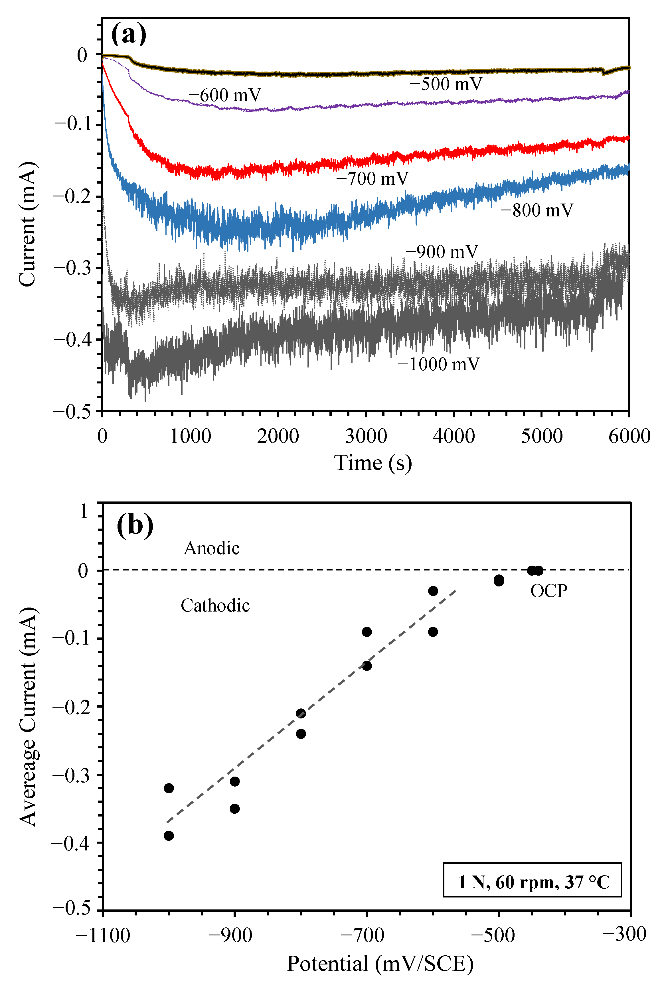
After establishing the OCP (−450 mV (SCE)) during sliding, a series of sliding tests were conducted potentiostatically at cathodic potentials ranging from −500 MV (SCE) to −1000 mV (SCE). Cathodic potentials more negative than −1000 mV (SCE) were not used in this work because tribocorrosion tests are rarely conducted under such conditions. Figure 2a shows the current transient curves recorded at 1 N load. Clearly, at all the applied potentials, the recorded currents were negative. At each potential, during the first 300 s immersion without sliding, the value of the negative current increased with time (i.e., the current shifted downwards in Figure 2a). During sliding, the value of the negative current increased first and then decreased. Figure 2a also shows that despite the noticeable scatter in cathodic current at each potential, there is a clear trend that the value of the cathodic current increased with increasing cathodic potential. At −500 mV (SCE), which was close to the OCP and was in the transition region between anodic dissolution and cathodic reduction, the value of the negative current was very small, around −0.01 mA. Increasing the value of cathodic potential to −1000 mV (SCE) increased the negative current to around −0.4 mA, which is 40 times the value at −500 mV (SCE). Figure 2b shows the average negative current measured during sliding at various applied cathodic potentials. As expected, the value of the negative current increased with increasing cathodic potential in the range between −500 mV (SCE) and −1000 mV (SCE) tested in this work.
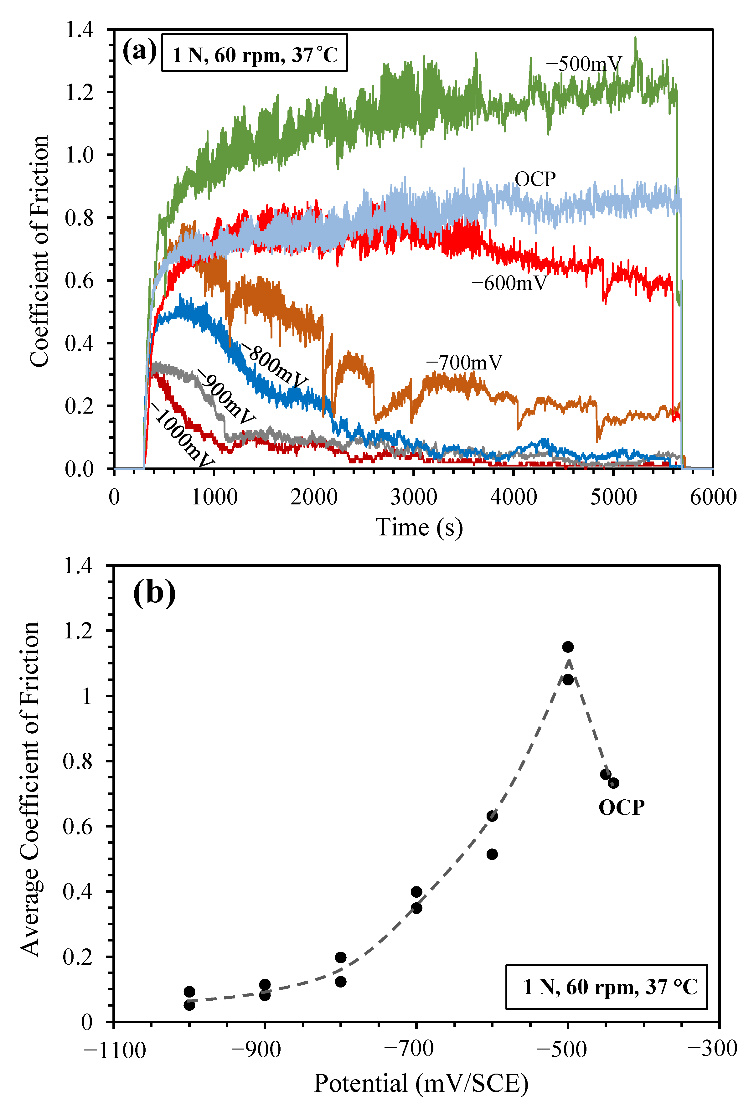
Figure 3a shows typical COF curves measured during sliding at various applied cathodic potentials. Several interesting observations can be made here. At OCP, the measured COF curve was similar to that reported previously [14], i.e., after the initial quick rise, the COF increased slowly with sliding time to reach values around 0.8. At −500 mV (SCE), the COF followed the same trend as that at OCP, but the overall COF values were much higher, reaching around 1.2 at the later stage of sliding. Higher friction when sliding at cathodic potentials has been observed during tribocorrosion testing of several passive metals [10,14,26], and this phenomenon is attributed to the lack of an oxide film at cathodic potentials, which could serve as a lubricant to reduce friction. However, this was true only when the applied cathodic potential was close to OCP, e.g., −500 mV (SCE). When the cathodic potential was increased to more negative than −600 mV (SCE), the friction behaviour of the sliding couple became quite different. At −600 mV (SCE), the COF was initially similar to that recorded at OCP, but started to decline after about 3000 s sliding. The most significant observation was that at cathodic potentials between −700 mV (SCE) and −1000 mV (SCE), the COF followed a very interesting characteristic pattern. At the early stage of sliding, the COF increased with time to reach a maximum value, then it decreased gradually to reach a relatively low and stable value. The stable COF value achieved decreased with increasing cathodic potential, i.e., at −1000 mV (SCE), the stable COF value achieved was as low as 0.02. From Figure 3a, it can also be seen that the critical sliding time, after which the stable low friction value was achieved, decreased with increasing cathodic potential. The maximum COF value measured during sliding at the early stage also decreased with increasing cathodic potential. Clearly, the present work demonstrates that increasing cathodic potential has the benefit of reducing friction during the entire sliding period, and such a friction-reducing ability becomes more effective after sliding for a certain period.
In Figure 3b, the average COF calculated for the entire sliding period in each test was plotted against applied cathodic potential. It clearly shows that sliding at −500 mV (SCE) led to an increase in average COF, and at further higher cathodic potentials, the average COF decreased with increasing potential to reach an average value below 0.1 at −1000 mV (SCE).
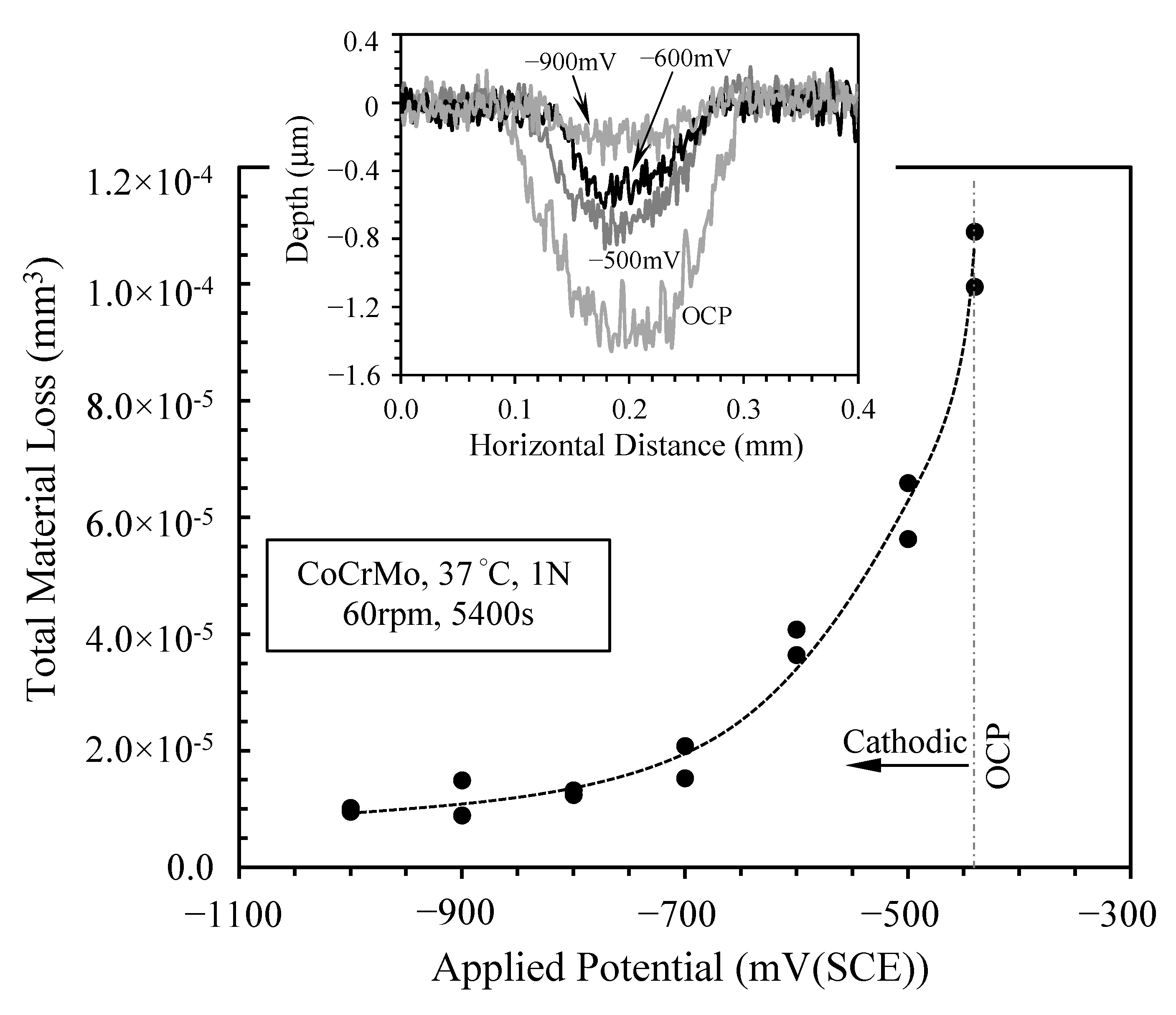
In line with the reduced COF as the applied cathodic potential was increased, the TML from the sliding track was also reduced. As shown in Figure 4, the TML decreased continuously as the value of cathodic potential was increased. The TML at −900 mV (SCE) and −1000 mV (SCE) was an order of magnitude lower than the TML at OCP. It is also noted that although the COF measured at −500 mV (SCE) was much larger than that measured at OCP (Figure 3), the TML at −500 mV (SCE) was smaller than that at OCP (Figure 4). The inset in Figure 4 shows typical sliding track profiles measured using a profilometer. Clearly, the sliding depth decreased with increasing value of cathodic potential. At OCP, the sliding depth was about 1.4 μm, whilst at −900 mV (SCE) it was less than 0.2 μm.
It has commonly been observed during tribocorrosion testing of passive metals that the TML measured at cathodic potentials is less than the TML measured at OCP and at anodic potentials, due to the diminished contribution of corrosion and the synergism between corrosion and mechanical wear to TML at cathodic potentials. Thus, TML measured at a cathodic potential has been commonly regarded as being mainly due to mechanical wear. This pure mechanical wear component, together with the measured TML and the current during sliding, has been used to derive the contribution of corrosion-wear synergism to TML at OCP and at anodic potentials [8,9,10,26]. However, the present work demonstrates that the TML at cathodic potentials does not have a single value even under the same mechanical loading and sliding conditions and it is potential-dependent. The TML at −500 mV (SCE) is 6 times larger than that at −1000 mV (SCE). Thus, there are other factors that can contribute to the mechanical wear at cathodic potentials, as discussed in Section 4.

3.3. Sliding at −900 mV(SCE) under Various Contact Loads

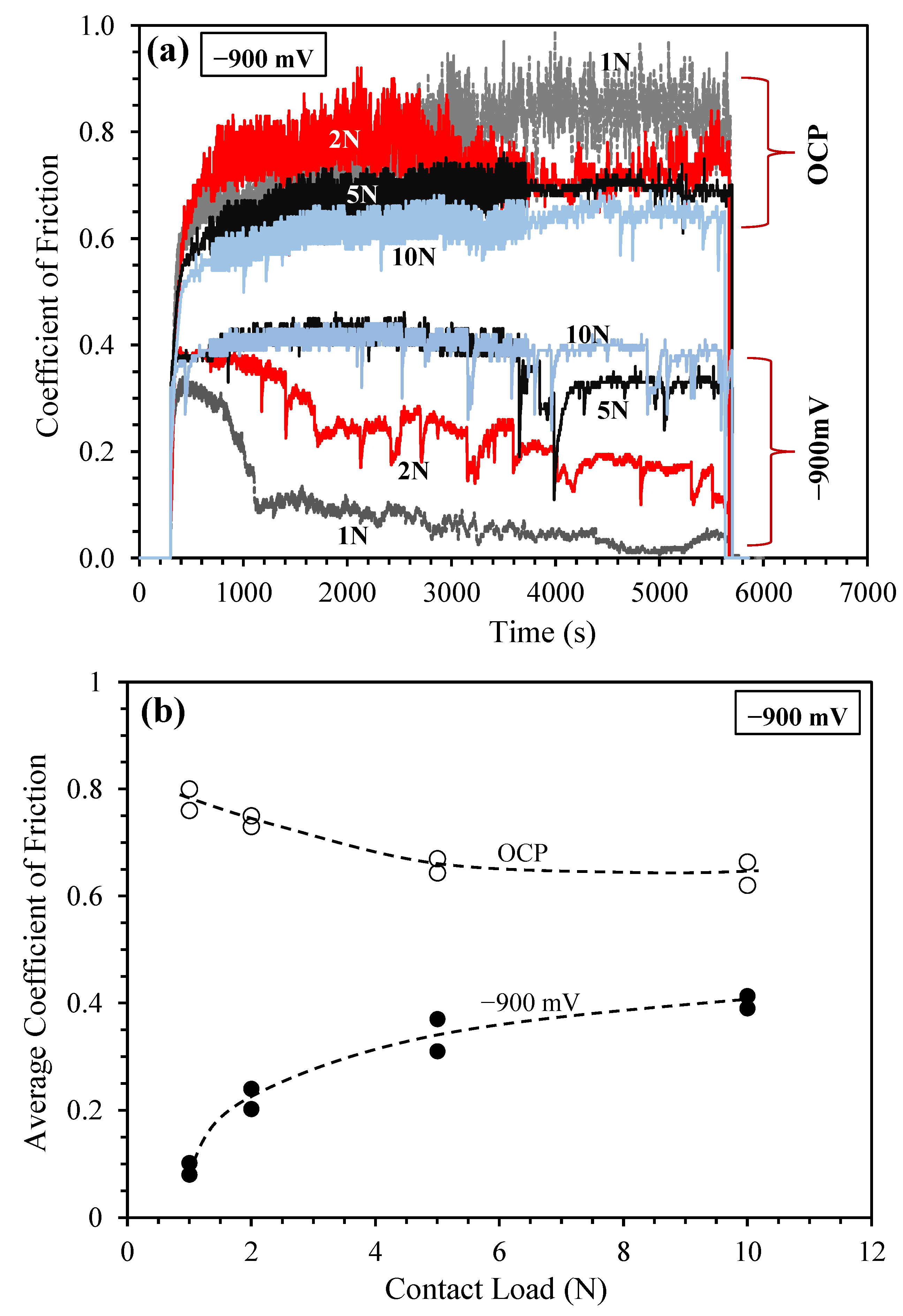
The results presented in Section 3.2 were obtained under a relatively small load of 1 N. A question can be raised here, i.e., whether the observed low COF and low TML at large cathodic potentials could also apply at higher contact loads. Thus, further experiments were conducted at −900 mV (SCE) under various loads from 1 N to 10 N. Figure 5 shows the recorded COF curves (Figure 5a) and the variation of average COF with load (Figure 5b). At OCP, friction decreased with increasing contact load, with the average COF decreased from about 0.8 under 1 N load to 0.65 under 10 N load. On the other hand, at −900 mV (SCE), friction was always lower than that at OCP under all employed contact loads and the variation of COF with load followed an opposite trend: COF increased with increasing load. The COF curves recorded at −900 mV (SCE) under small loads, e.g., 1 N and 2 N, follow a similar pattern: the COF rose rapidly during the early stage to reach a maximum value, and then it decreased gradually to reach low values below 0.2 under 2 N load, and below 0.05 under 1 N load. The COF under 2 N load was always larger than that under 1 N load. However, when the high contact load of 10 N was applied, the COF value was maintained at a constant value of around 0.4 throughout the sliding period.
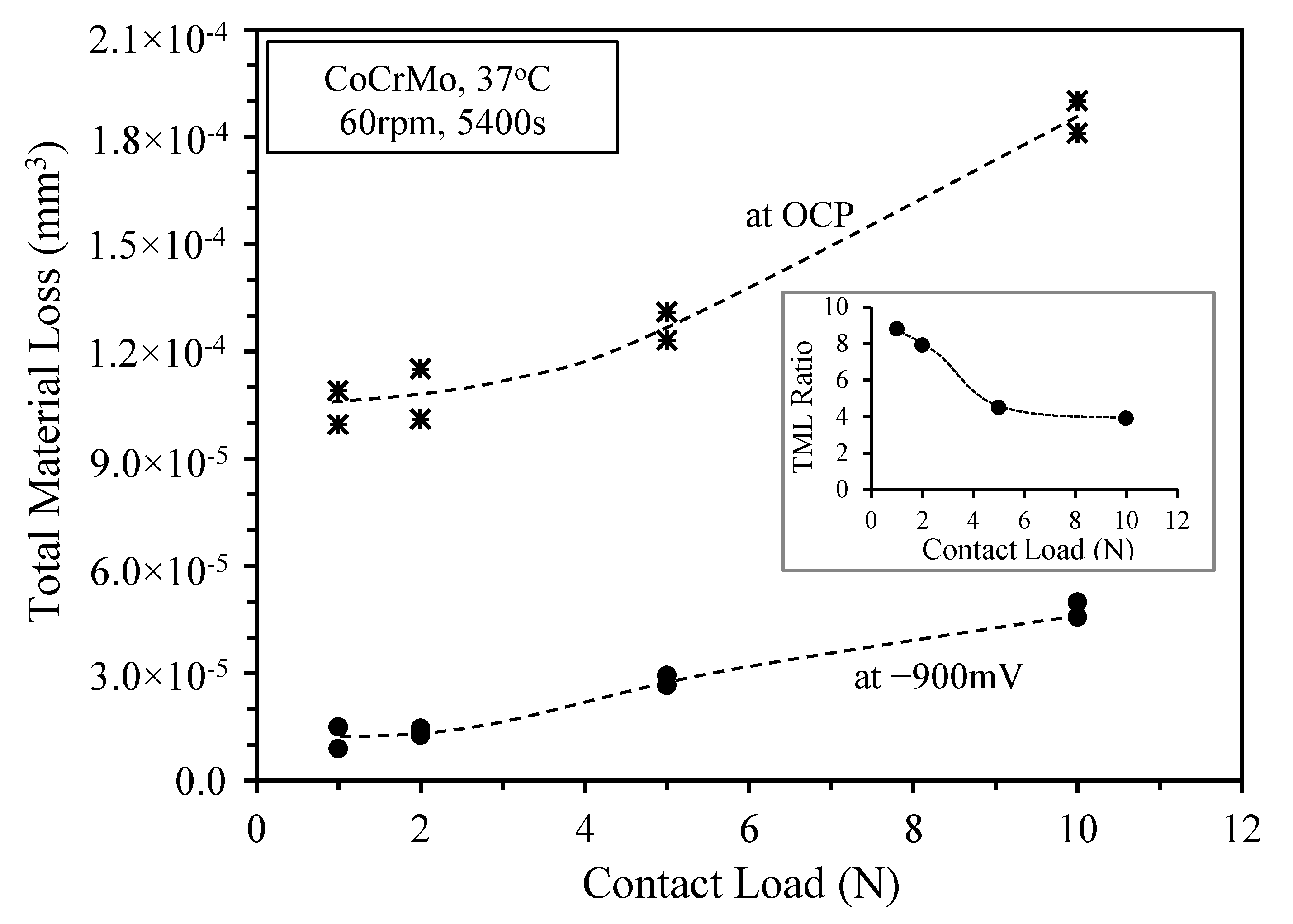
Figure 6 shows the measured TML from the sliding track as a function of contact load at OCP and at −900 mV (SCE). The TML increased with load at both potentials, which is expected from the general principle of wear: increased mechanical loading leads to increased mechanical wear. At −900 mV (SCE), the TML under all loads was much smaller than that measured at OCP, indicating the cathodic protection ability of the alloy. In the inset of Figure 6, the ratio of TML at OCP to that at −900 mV (SCE) was plotted as a function of load. Clearly, this ratio decreased with increasing load, indicating decreasing cathodic protection as load was increased. Under 1 N load, the TML at OCP was 9 times larger than that at −900 mV (SCE). Increasing the load to 5 N and 10 N, the TML at OCP was about 4 times larger than that at −900 mV (SCE).
The above observation on the effect of contact load on cathodic protection agrees with the observation of Akonka et al. [11] on stainless steel sliding at cathodic potentials, who observed that sliding at cathodic potentials resulted in much lower wear rates than sliding at OCP, and such cathodic protection disappeared under high contact loads. Akonka et al. [11] attributed such a phenomenon to the hydrogen charging at the cathodic potential.

3.4. Morphology of Sliding Tracks

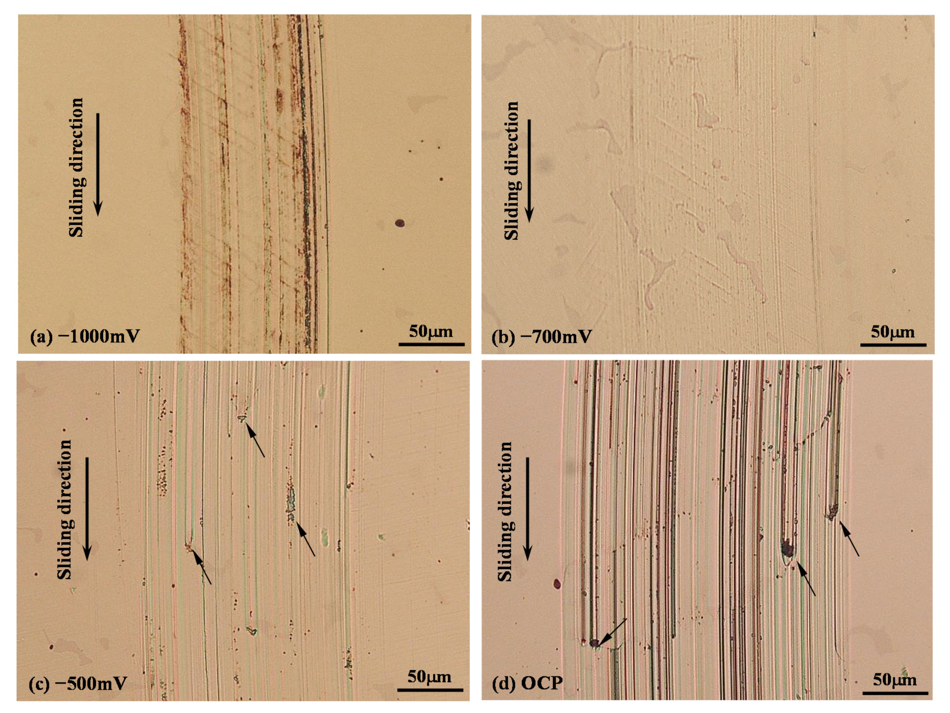
Microscopic images of the sliding tracks generated at various cathodic potentials are shown in Figure 7. The morphological features of the sliding tracks can be divided into two groups. At potentials less negative than −600 mV (SCE), including OCP and −500 mV (SCE), the sliding tracks were characterized by the existence of many scratch marks, i.e., grooves of abrasive wear, parallel to the sliding direction (Figure 7c,d). Some of the scratches were not continuous, but terminated within the track with some third-body particles (arrowed in Figure 7c,d). It is believed that the wear particles were accumulated on the sliding track and stuck on the counterface to cause abrasive wear of the surface. There were no cracks observed in the sliding tracks produced at OCP, −500 mV (SCE) and −600 mV (SCE). However, the scratches in the wear track produced at OCP were much wider and deeper than those produced at −500 mV (SCE) and −600 mV (SCE). The corrosion-wear products resulted from removing the oxide film at OCP may be responsible for the increased abrasion of the surface.
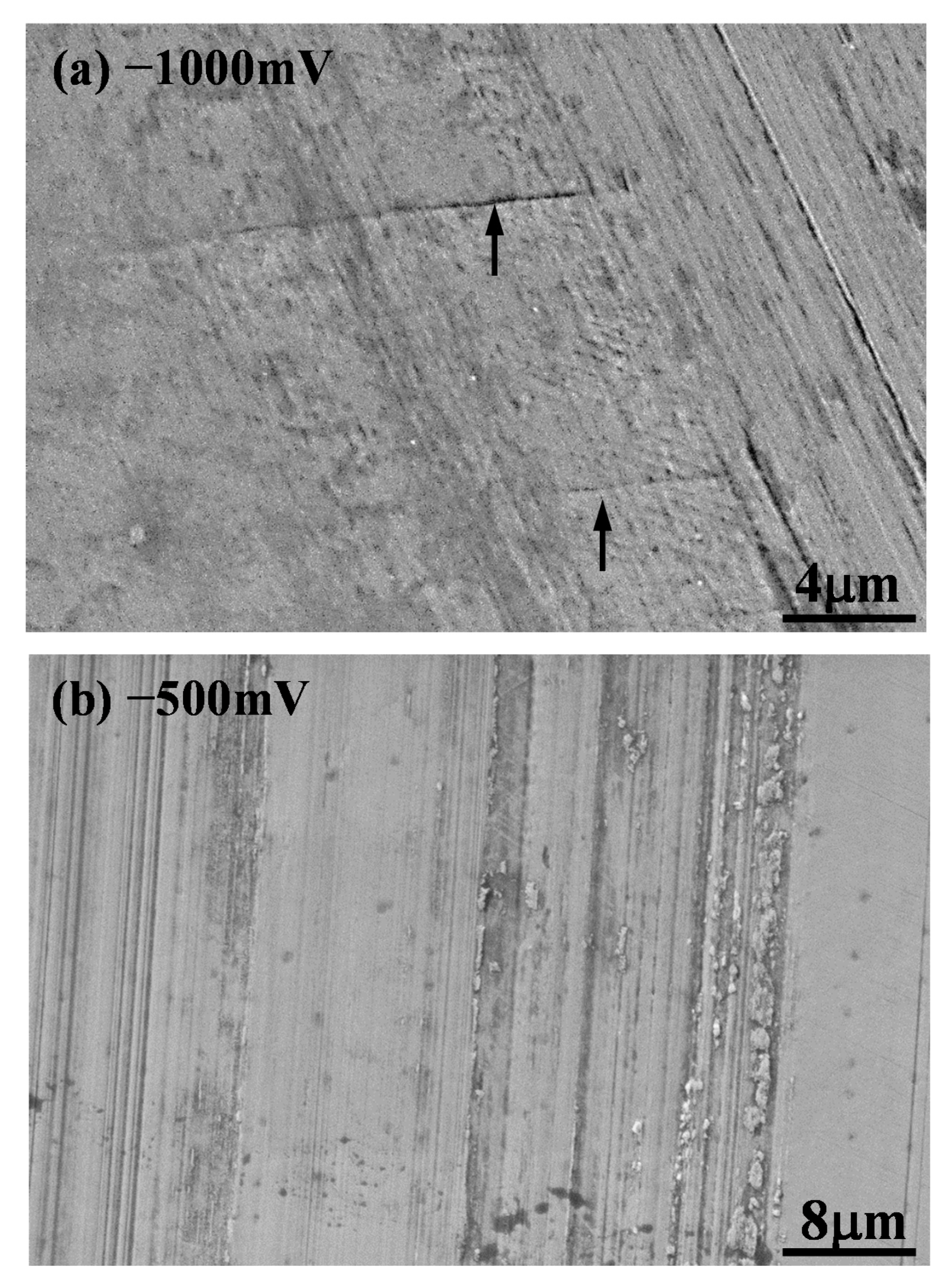
Another group of sliding tracks include those produced at potentials more negative than −600 mV (SCE) (Figure 7a,b). These sliding tracks were characterized by two distinct features, i.e., (1) the existence of fine scratch marks caused by the micro-abrasion of the counterface, and (2) the presence of many parallel lines which were inclined to the sliding direction. Most of these lines could hardly be observed under microscopes. Only through very careful examination by slightly adjusting the focus could the lines be revealed clearly. These lines were formed across the sliding track and did not extend far beyond the track. Figure 8a shows a high magnification SEM image revealing two parallel lines with a spacing about 9 μm on the −1000 mV (SCE) sliding track. It is also noted from Figure 8a that the line opening was very narrow, about 0.1 μm, which has imposed some difficulty in revealing the lines under microscopes. Figure 8b shows an SEM image of the sliding track generated at −500 mV (SCE). Clearly, no such lines were observed in the sliding track which was populated with abrasion marks with accumulated wear particles which could serve as third-body abrasives during the sliding process.
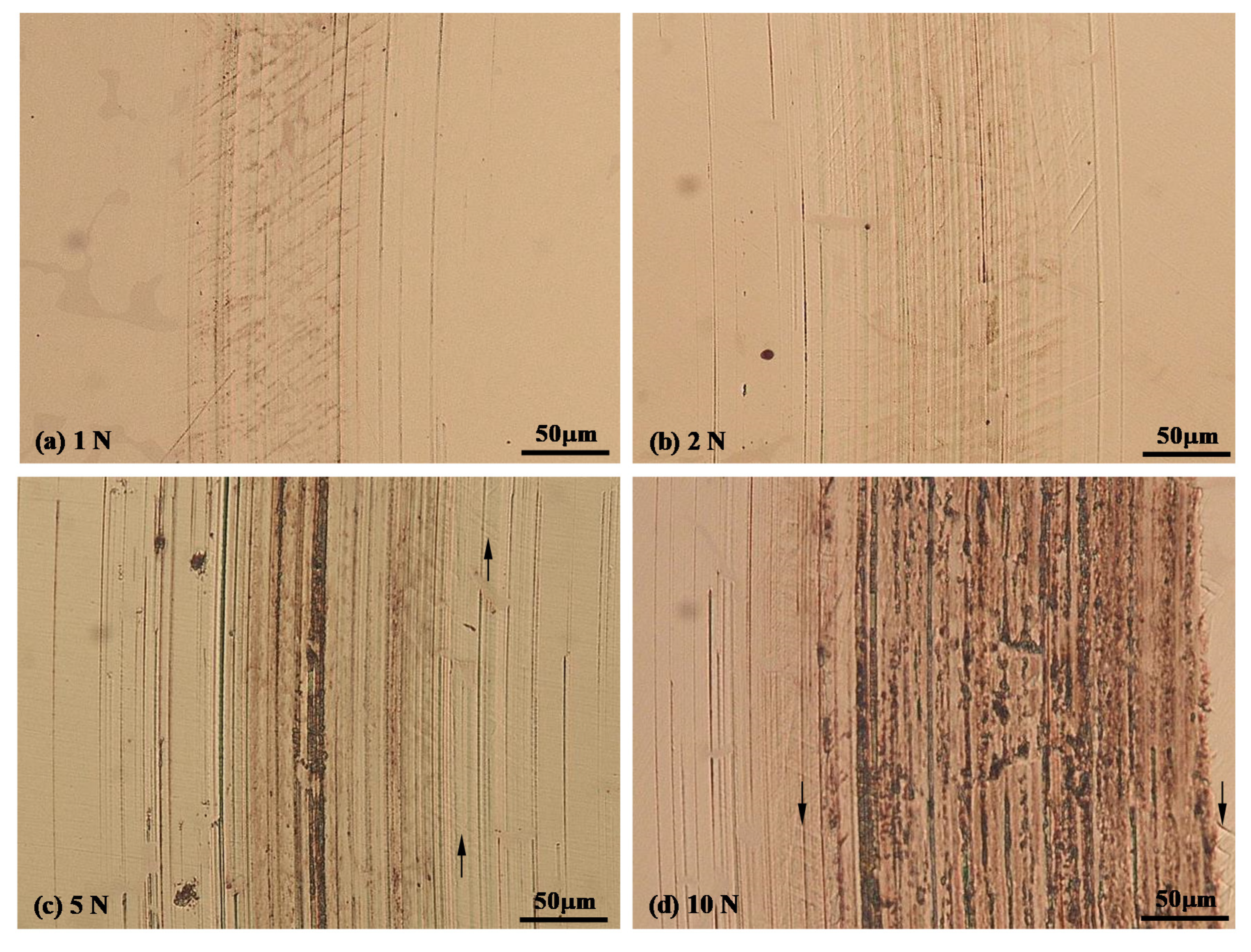
Similarly, the sliding tracks produced at −900 mV (SCE) under various contact loads can also be divided into two groups (Figure 9). The sliding tracks produced under relatively small loads, e.g., 1 N and 2 N, belong to one group, which were characterized by the existence of fine and parallel micro-abrasion marks and the presence of parallel lines across the sliding track (Figure 9a,b). On the other hand, the sliding tracks produced under higher loads, e.g., 5 N and 10 N, belong to another group (Figure 9c,d), which were characterized by the existence of wider and deeper scratch marks in the central region of the track, where no such lines were observed. However, near to the edges of these sliding tracks, where the scratch marks were finer and abrasive wear was less severe, such lines could be observed (arrowed areas in Figure 9c,d). Thus, it is likely that such lines also formed across the sliding tracks under 5 N and 10 N loads, but in the central area of the track, the lines were removed due to enhanced material removal in this region.

4. Discussion

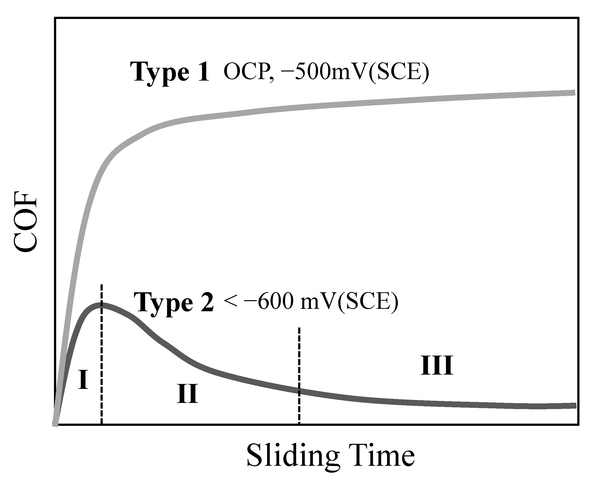
The investigated CoCrMo alloy is a passive alloy with an oxide film before the sliding tests. During sliding, the oxide film is damaged or even removed such that the OCP is cathodically shifted from around −320 mV (SCE) to −450 mV (SCE). Sliding tests at cathodic potentials ranging from −500 mV (SCE) to −1000 mV (SCE) in this work illustrate that the friction and wear behaviour depends on the cathodic potential and the load applied. The friction behaviour can be divided into two types, as evidenced in Figure 3a and schematically illustrated in Figure 10. Type 1 is characterized by the gradual increase in COF during the early stage of sliding to reach a steady state. This frictional behaviour was observed at OCP and −500 mV (SCE). Type 2, which is observed at potentials more cathodic than −600 mV (SCE), is characterised by 3 distinct frictional zones: in Zone I, COF increases with sliding time during the early stage; in Zone 2, COF decreases gradually with time as sliding continues; and in Zone 3, relatively stable and low COF is achieved. The COF values in each zone and the time to reach each zone decrease with increasing cathodic potential.
In the cathodic potential range tested in this work, there are three possible cathodic reduction reactions, i.e., oxygen, proton and water reductions [24,27]. Oxygen reduction can occur at potentials below OCP, thus the prior existing oxide film may be dissolved at applied cathodic potentials. However, the oxide film on CoCrMo alloy mainly comprises chromium oxide that cannot be dissolved cathodically [27,28]. Thermodynamically, the proton reduction can only occur at potentials below the reversible potential, i.e., more negative than −650 mV (SCE) for the present pH (7.2) and temperature (37 °C). Proton reduction can lead to the adsorption of hydrogen on the cathode surface, forming a hydrogen segregation layer at the metal surface [29,30]. This critical cathodic potential coincides with the experimental result that only at potentials below −600 mV (SCE) is the characteristic low friction behaviour observed (type 2 in Figure 10). Thus, hydrogen charging seems have played a key role here. However, the concentration of protons at pH7.2 is very low and its contribution to overall current and hydrogen charging is also low. The most likely reduction reaction is water reduction, which is kinetically inhibited until a sufficient overpotential is applied below the reversible potential. It is expected that at potentials below −700 mV (SCE), water reduction occurs, which starts with the adsorption of H on the metal surface. The recombination of two adsorbed H leads to the formation of H2 molecule and hydrogen evolution [31]. In many cases, depending on the nature of the metal surface, a H segregated layer, in the form of either a solid solution or metal hydrides, is formed at the surface, leading to changes in structures and properties of the surface. Accordingly, the two types of friction behaviour observed in this work (Figure 10) can be explained as follows.
At OCP and −500 mV (SCE), hydrogen reduction is inhibited and thus the surface is free from hydrogen segregation. Sliding under these two conditions exhibits similar frictional behaviour (Type 1). COF increases with time during the early stage of sliding, because of the gradual removal of the prior existing oxide film and the gradual increase in contact area, until a steady stage is reached. At OCP, the oxide film is removed or damaged after each sliding cycle but is reformed during each sliding interval, while at −500 mV (SCE), once the prior existing oxide film is removed, reformation of the oxide film during sliding interval is inhibited because at this cathodic potential oxygen reduction is preferred. Thus, the COF at OCP is smaller than that at −500 mV (SCE) because the formation of an oxide film helps to reduce friction [10]. However, when the TML from the sliding track is concerned, Figure 4 clearly shows that the TML at −500 mV (SCE) is actually smaller than that at OCP. This can be explained by the lack of contribution of corrosion and the synergism between corrosion and mechanical wear to TML at cathodic potentials. Thus the TML at −500 mV (SCE) can be treated as the result of pure mechanical wear without much of a contribution from corrosion and hydrogen charging. The principle wear mechanism is abrasive wear, evidenced by the sliding track morphology (Figure 7c and Figure 8b).
At cathodic potentials from −700 mV (SCE) to −1000 mV (SCE), type 2 frictional behaviour was observed (Figure 3a), which can be related to hydrogen charging. The amount of H adsorption depends on the electrolyte, the applied potential, the electrocatalyst nature of the metal surface, and particularly the number of active sites on the surface [31,32]. It is understood that mechanical loading, shear deformation and surface roughening can accelerate the adsorption of hydrogen due to increased active sites [33,34]. At a constant cathodic potential, during the early stage of sliding, hydrogen segregation is not built up yet. As the slider slides over the surface, the contact area is increased with time and so does friction, leading to the observed Zone I in Figure 10. Meanwhile, a sliding track is gradually generated on the surface with increased surface damage and roughness, accelerating the formation of a hydrogen segregated layer inside the sliding track, which leads to the gradual reduction in friction (Zone II). Once a hydrogen segregated layer is established in the sliding track, a stable and low friction region is reached, i.e., Zone III. At each sliding cycle, the hydrogen segregated layer is damaged or removed due to the sliding action, and reformed at each sliding interval. Increasing cathodic potential accelerates the formation of the hydrogen segregated layer and moves the friction curve downwards, reducing the length of Zone I and Zone II and the COF in Zone III (Figure 3). Increasing contact loads increases the material removal rate, thus the hydrogen segregated layer is removed at a higher rate, resulting in the shift of the friction curve upwards (Figure 5). The parallel lines formed at high contact loads may not diminish, but the abrasive wear prevents the direct observation of the cracks.
Although no chemical and composition analysis was conducted due to the dynamic nature of the H-segregated layer and the small size of the sliding track area, the formation of an H-segregated layer can be confirmed positively by the formation of many parallel lines across the sliding tracks produced at potentials more negative than −700 mV (SCE), see Figure 7, Figure 8 and Figure 9. It is well known that hydrogen adsorption leads to the embrittlement of metals. Under the conditions where hydrogen charging is prohibited, i.e., at OCP and −500 mV (SCE), no such lines were observed in the sliding tracks. Thus, parallel line formation at larger cathodic potentials may be the result of hydrogen charging and embrittlement. It is believed that these parallel lines are twins and stacking-faults due to strain-induced martensitic transformation assisted by hydrogen charging. It is possible that martensite phase transformation by dynamic recrystallisation occurs due to hydrogen charging during the sliding process [35,36].
The effect of cathodic hydrogen charging on the friction and wear of metals has been the subject of several recent studies [17,18,19,20]. Although hydrogen adsorption can lead to embrittlement of the sliding surface, it may have some beneficial effect on tribological properties. Recently, Georgiou et al. [18] found that hydrogen incorporation under in-situ cathodic polarization can significantly reduce the COF of an aluminium alloy under reciprocating conditions, but increase the wear rate of the alloy due to embrittlement. Pokhmurskii et al. [21] found that electrolytic hydrogenation can increase the surface hardness and reduce the friction of α-titanium, although its ductility was reduced. The possible formation of metal hydrides with crystal structures favourable for friction reduction can also account for the observed reduction in friction.

5. Conclusions

The effect of applied cathodic potential on the sliding friction and wear behaviour of CoCrMo alloy in NaCl solution has been systematically studied over a wide range of cathodic potentials and applied contact loads. It can be concluded that applied cathodic potential affects the friction and wear behaviour of the alloy in two different ways. At cathodic potentials close to the open circuit potential, high friction and relatively large material loss results, where material loss is predominantly due to mechanical wear. At potentials more cathodic than the hydrogen charging potential, low friction and low wear result. The COF and TML decrease with increasing cathodic potential, such that at large cathodic potentials, e.g., −1000 mV (SCE), COF values as low as 0.02, and negligible material loss are obtained. Such reductions in friction and wear at increasing cathodic potentials are accompanied with the formation of parallel lines in the sliding track and are gradually diminished with increasing applied contact load due to increased material removal. Hydrogen charging and the formation of a hydrogen-segregated layer at the surface are believed to be responsible for such a phenomenon. It can also be concluded that it is difficult to derive the pure mechanical wear component in tribocorrosion by simply conducting a test at an arbitrary cathodic potential. The results have a further implication that material degradation during sliding wear in a corrosive environment could be minimised through appropriate cathodic protection.

Author Contributions

Conceptualization, Y.S.; methodology, Y.S. and R.B.; experimentation, Y.S. and R.B.; formal analysis, Y.S.; investigation, R.B.; writing—original draft preparation, Y.S.; writing—review and editing, R.B. All authors have read and agreed to the published version of the manuscript.

Funding

This research received no external funding.

Conflicts of Interest

The authors declare no conflict of interest.

References

  1. Lemaire, E.; le Calvar, M. Evidence of tribocorrosion wear in pressurized water reactors. Wear 2001, 249, 338–344. [Google Scholar] [CrossRef]
  2. Watson, S.W.; Friedersdorf, F.J.; Madsen, B.W.; Cramer, S.D. Methods of measuring wear-corrosion synergism. Wear 1995, 181, 476–484. [Google Scholar] [CrossRef]
  3. Luo, C.; Ji, X.; Ji, C.; Zhang, Y.; Wang, H. Tribocorrosion of Fe-based amorphous coating in simulated body fluids. Lubricants 2018, 6, 37. [Google Scholar] [CrossRef] [Green Version]
  4. Jiang, J.; Stack, M.M.; Neville, A. Modelling the tribo-corrosion interaction in aqueous sliding conditions. Tribol. Int. 2002, 35, 669–679. [Google Scholar] [CrossRef]
  5. Li, X.; Dou, W.; Tian, L.; Dong, H. Combating the tribo-corrosion of LDX2404 lean duplex stainless steel by low temperature plasma nitriding. Lubricants 2018, 6, 93. [Google Scholar] [CrossRef] [Green Version]
  6. Mischler, S. Triboelectrochemical techniques and interpretation methods in tribocorrosion: A comparative evaluation. Tribol. Int. 2008, 41, 573–583. [Google Scholar] [CrossRef]
  7. Ponthiaux, P.; Wenger, F.; Drees, D.; Celis, J.P. Electrochemical techniques for studying tribocorrosion processes. Wear 2004, 256, 459–468. [Google Scholar] [CrossRef]
  8. Tao, S.; Li, D.Y. Investigation of corrosion-wear synergistic attach on nanocrystalline Cu deposits. Wear 2007, 263, 363–370. [Google Scholar] [CrossRef]
  9. Benea, L.; Ponthiaux, P.; Wenger, F.; Galland, J.; Hertz, D.; Malo, J.Y. Tribocorrosion of stellite 6 in sulphuric acid medium: Electrochemical behavior and wear. Wear 2004, 256, 948. [Google Scholar] [CrossRef]
  10. Sun, Y.; Rana, V. Tribocorrosion behaviour of AISI 304 stainless steel in 0.5M NaCl solution. Mater. Chem. Phys. 2011, 129, 138–147. [Google Scholar] [CrossRef]
  11. Akonko, S.; Li, D.Y.; Ziomek-Moroz, M. Effect of cathodic protection on corrosive wear of 304 stainless steel. Trib. Lett. 2005, 18, 405–410. [Google Scholar] [CrossRef]
  12. Munoz, A.I.; Julian, L.C. Influence of electrochemical potential on the tribocorrosion behaviour of high carbon CoCrMo biomedical alloy in simulated body fluids by electrochemical impedance spectroscopy. Electrochim. Acta 2010, 55, 5428–5439. [Google Scholar] [CrossRef]
  13. Favero, M.; Stadelmann, P.; Mischler, S. Effect of applied potential on the near surface microstructure of a 316L steel submitted to tribocorrosion in sulfuric acid. J. Phys. D Appl. Phys. 2006, 39, 3175. [Google Scholar] [CrossRef]
  14. Sun, Y.; Dearnley, P.A. Tribocorrosion behaviour of duplex S/Cr(N) and S/CrC coatings on CoCrMo alloy in 0.89% NaCl solution. J. Bio Tribo-Corros. 2015, 1, 1–13. [Google Scholar] [CrossRef]
  15. Song, J.; Curtin, W.A. Mechanisms of hydrogen-enhanced localized plasticity: An atomistic study using α-Fe as a model system. Acta Mater. 2014, 68, 61–69. [Google Scholar] [CrossRef]
  16. Liang, X.; Gao, X.; Yang, H.; Yu, L. Effect of static hydrogen charging on corrosion and hydrogen embrittlement of high speed steel. IOP Conf. Ser. Mater. Sci. Eng. 2018, 423, 012049. [Google Scholar]
  17. Murakami, T.; Mano, H.; Kaneda, K.; Hata, M.; Sasaki, S.; Sugimura, J. Friction and wear properties of zirconium and niobium in a hydrogen environment. Wear 2010, 268, 721–729. [Google Scholar] [CrossRef]
  18. Georgiou, E.P.; Cevallos, V.P.; van der Donck, T.; Drees, D.; Meersschaut, J.; Panagopoulos, C.N.; Celis, J.-P. Effect of cathodic hydrogen charging on the wear behaviour of 5754 Al alloy. Wear 2017, 390, 295–301. [Google Scholar] [CrossRef]
  19. Amoush, A.S.E. Investigation of wear properties of hydrogenated tin brass heat exchanger. J. Alloys Compd. 2008, 448, 257–262. [Google Scholar] [CrossRef]
  20. Zhang, T.C.; Jiang, X.X.; Li, S.Z. Hydrogen-induced embrittlement wear of a high-strength low alloy steel in an acidic environment. Corrosion 1997, 53, 200–205. [Google Scholar] [CrossRef]
  21. Pokhmurskii, V.I.; Vynar, V.A.; Vasyliv, C.h.B.; Ratska, N.B. Effects of hydrogen exposure on the mechanical and tribological properties of α-titanium surfaces. Wear 2013, 306, 47–50. [Google Scholar] [CrossRef]
  22. Cassar, J.; Mallia, B.; Mazzonello, A.; Karl, A.; Buhagiar, J. Improved tribocorrosion resistance of a CoCrMo implant material by carburizing. Lubricants 2018, 6, 76. [Google Scholar] [CrossRef] [Green Version]
  23. Mischler, S.; Munoz, A.I. Wear of CoCrMo alloys used in metal-on-metal hip joints: A tribocorrosion appraisal. Wear 2013, 297, 1081–1094. [Google Scholar] [CrossRef]
  24. Wang, Z.; Yan, Y.; Su, Y.; Qiao, L. Effect of electrochemical corrosion on the subsurface microstructure evolution of a CoCrMo alloy in albumin containing environment. Appl. Surf. Sci. 2017, 406, 319–329. [Google Scholar] [CrossRef]
  25. Quiram, G.; Gindri, I.M.; Kerwell, S.; Shull, K.; Mathew, M.T. Nanoscale mechanical evaluation of electrochemically generated tribolayer on CoCrMo alloy for hip joint application. J. Bio Tribo-Corros. 2016, 2, 15. [Google Scholar] [CrossRef] [Green Version]
  26. Ji, X.; Luo, C.; Sun, Y.; Zhao, J. Corrosive wear of multi-layer Fe-based coatings laser cladded from amorphous powders. Wear 2019, 438, 203113. [Google Scholar] [CrossRef]
  27. Munoz, A.I.; Mischler, S. Electrochemical quartz crystal microbalance and X-ray photoelectron spectroscopy study of cathodic reactions in bovine serum albumin containing solutions on a physical vapour deposition CoCrMo biomedical alloy. Electrochem. Acta 2015, 180, 96–103. [Google Scholar] [CrossRef]
  28. Sinnett-Jones, P.E.; Wharton, J.A.; Wood, R.J.K. Micro-abrasion-corrosion of CoCrMo alloy in simulated artificial hip joint environments. Wear 2005, 259, 898–909. [Google Scholar] [CrossRef]
  29. Rosenak, P. Defects producing formation of micro-cracks in aluminum during electrochemical charging with hydrogen. J. Alloys Comp. 2005, 400, 106–111. [Google Scholar] [CrossRef]
  30. Escobar, D.P.; Minambre, C.; Duprez, L.; Verbeken, K.; Verhaege, M. Internal and surface damage of multiphase steels and pure iron after electrochemical hydrogen charging. Corros. Sci. 2011, 53, 3166–3176. [Google Scholar] [CrossRef]
  31. Safizadeh, F.; Ghali, E.; Houlachi, G. Electrocatalysis developments for hydrogen evolution reaction in alkaline solutions—A Review. Int. J. Hydrogen Energy 2015, 40, 256–274. [Google Scholar] [CrossRef]
  32. Eftekhari, A. Electrocatalysts for hydrogen evolution reaction. Int. J. Hydrogen Energy 2017, 42, 11053–11077. [Google Scholar] [CrossRef]
  33. Hardie, D.; Liu, S. The effect of stress concentration on hydrogen embrittlement of a low alloy steel. Corros. Sci. 1996, 38, 721–733. [Google Scholar] [CrossRef]
  34. Su-Il, P.; Jong-Sang, K.; Frisch, B.; Messerschmidt, C. Steady state hydrogen evolution enhanced during the abrasive wear from mild steel. Wear 1998, 124, 331–336. [Google Scholar] [CrossRef]
  35. Chen, Y.; Li, Y.; Kurosu, S.; Yamanaka, K.; Tang, N.; Koizumi, Y.; Chiba, A. Effects of sigma phase and carbide on the wear behavior of CoCrMo alloys in Hanks’ solution. Wear 2014, 310, 51–62. [Google Scholar] [CrossRef]
  36. Buscher, R.; Fischer, A. The pathways of dynamic recrystallization in all-metal hip joints. Wear 2005, 259, 887–897. [Google Scholar] [CrossRef]
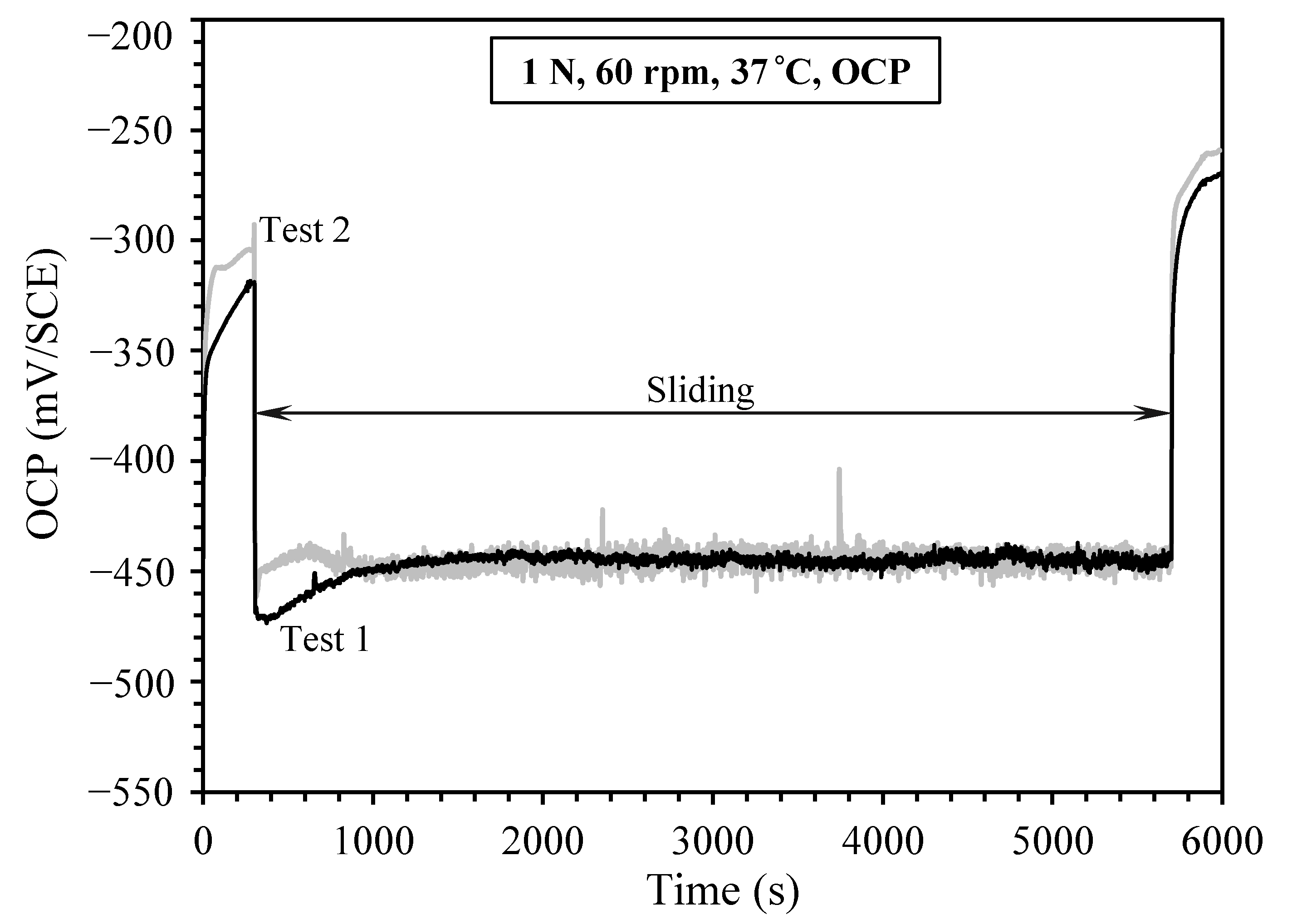
Figure 1. Recorded open circuit potential (OCP) before, during and after sliding under a contact load of 1 N in 0.9% NaCl solution at 37 °C, for two repeated tests.
Lubricants 08 00101 g001
Figure 2. (a) Recorded currents at various cathodic potentials under a contact load of 1 N in 0.9% NaCl solution at 37 °C, and (b) Average current during sliding as a function of applied cathodic potential.
Lubricants 08 00101 g002
Figure 3. (a) Recorded coefficient of friction (COF) curves during sliding at OCP and at various applied cathodic potentials under 1 N load; and (b) measured average COF versus applied cathodic potential.
Lubricants 08 00101 g003
Figure 4. Total material loss (TML) versus applied cathodic potential after sliding at 1 N load for 5400 s. Th inset shows typical cross-sectional profiles of the sliding tracks measured by a profilometer.
Lubricants 08 00101 g004
Figure 5. (a) Recorded COF curves at OCP and at −900 mV (saturated calomel electrode, SCE) under various contact loads; and (b) measured average COF as a function of load.
Lubricants 08 00101 g005
Figure 6. TML versus contact load, measured from the sliding tracks after sliding at −900 mV (SCE) for 5400 s under various contact loads from 1 N to 10 N. The inset shows the ratio of TML at OCP to TML at −900 mV (SCE) as a function of load.
Lubricants 08 00101 g006
Figure 7. Microscopic images of the sliding tracks generated under 1 N load at OCP and various applied cathodic potentials. The small arrows indicate the terminated scratches with third-body particles. (a) −1000 mV, (b) −700 mV, (c) −500 mV and (d) OCP.
Lubricants 08 00101 g007
Figure 8. Scanning electron microscope (SEM) images of the sliding tracks generated under 1 N load at (a) −1000 mV(SCE) revealing the parallel lines (arrowed), and (b) −500 mV (SCE) showing no such line formation.
Lubricants 08 00101 g008
Figure 9. Microscopic images of the sliding tracks generated at −900 mV (SCE) under various contact loads, (a) 1 N, (b) 2N, (c) 5 N and (d) 10 N.
Lubricants 08 00101 g009
Figure 10. Schematic diagram showing the two different categories of friction curves.
Lubricants 08 00101 g010
Publisher’s Note: MDPI stays neutral with regard to jurisdictional claims in published maps and institutional affiliations.