3.1. Prediction of Friction
The minimum lubricant film thickness is evaluated under the hydrodynamic regime of lubrication with an assumed Reynolds’ contact exit boundary condition for a rigid line contact [
49] as:
where,
,
,
and
are contact load, lubricant entrainment velocity, lubricant viscosity, and the minimum film thickness, respectively. Since the pin surface is not flat, friction due to viscous shear,
, is obtained as:
For a fully flooded condition (i.e., hydrodynamic regime of lubrication), the wetted contact area is
. For partially flooded contacts with a curved profile (i.e., mixed regime of lubrication), the real wetted area becomes:
. The upper limit of the integral,
(denoting the position of lubricant film rupture at the contact exit) is determined through solution of Equation (6) for the inlet/outlet boundary conditions (atmospheric pressure,
) [
50]:
Thus, the wetted region of contact area is calculated as:
where
denotes film thickness at any position across the contact. In mixed regime of lubrication, the contact load is partly carried by a lubricant film and partly by the contacting asperities on the counter face surfaces. The Hertzian theory of elastic contact between a pair of spherical surfaces is extended by considering several discrete spherical microcontacts at the scale of asperities. Asperity contact load,
, and their area of contact,
, vary with surface parameters and material properties as [
51]:
and
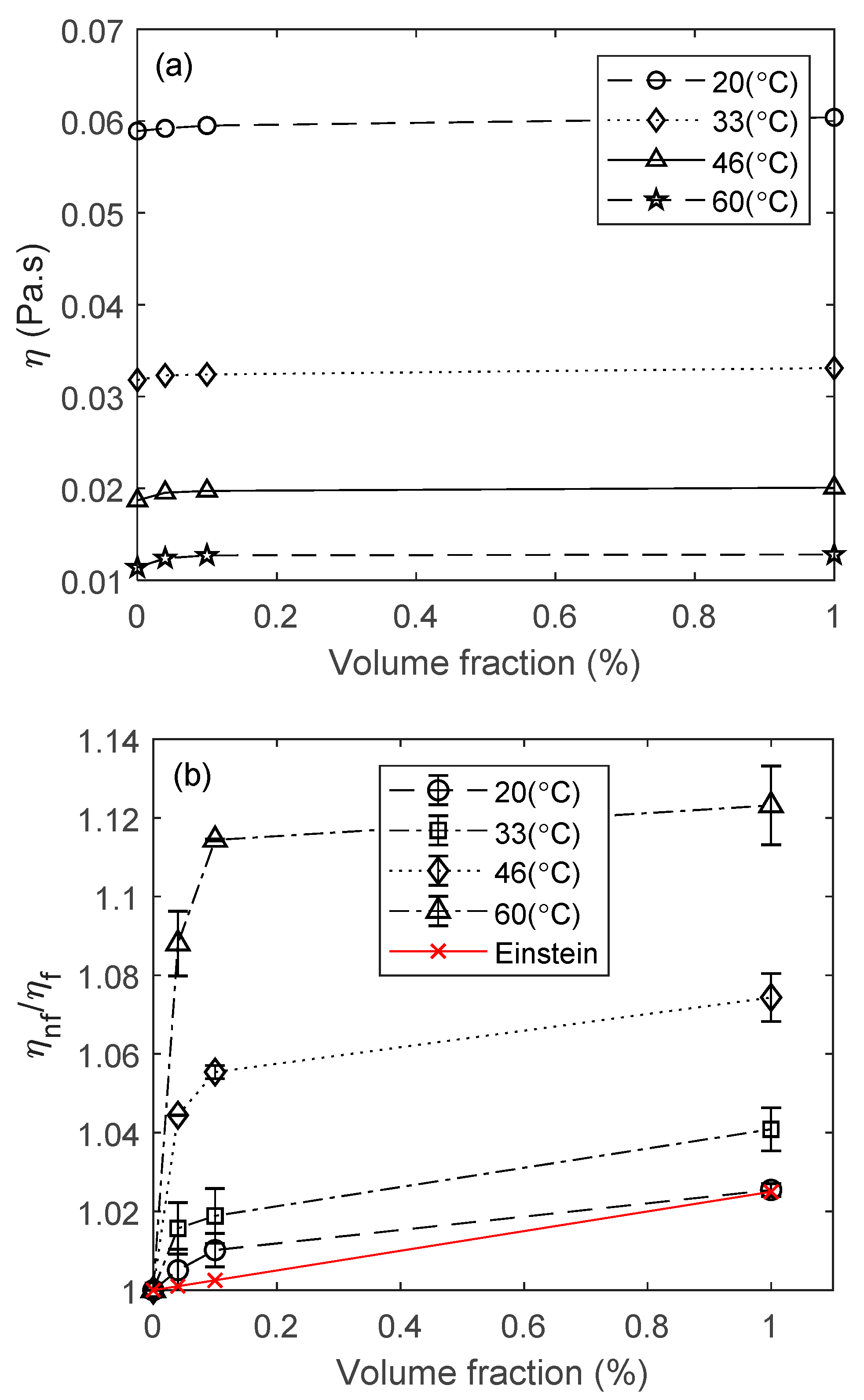
where the surface parameters
,
and
are extracted from
Figure 2 and presented in
Table 5. The statistical functions
describe the probability of counter face asperity interactions for an assumed Gaussian distribution of asperity heights [
49]. Greenwood and Tripp [
51] show explicitly that contact load and area are proportional to the compliance of asperities,
multiplied by the Gaussian exponential distribution of asperity heights Equation (10). The exponent
is 5/2 and 2 for contact load and area respectively Equations (8) and (9). Since the pin profile is not flat, these functions are integrated over the contact area. The statistical functions are approximated using exponential curve fits in Equations (11) and (12).
is the Stribeck’s oil film parameter [
52], indicating the distance between the mean plane of counter face
real rough surfaces, and so thus:
The generated frictional contribution due to direct asperity interactions (boundary friction),
, becomes [
51]:
It is assumed that a thin layer of lubricant is adsorbed into the asperity summits and the interspatial asperity valleys, acting with non-Newtonian Eyring shear stress,
[
53,
54,
55]. The boundary shear strength of the surfaces,
, is taken as 0.22 as measured using lateral force microscopy for a range of similar contacting materials by Umer et al. [
56]. Therefore, for a prevailing mixed regime of lubrication, the predicted contact friction,
, becomes:
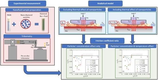
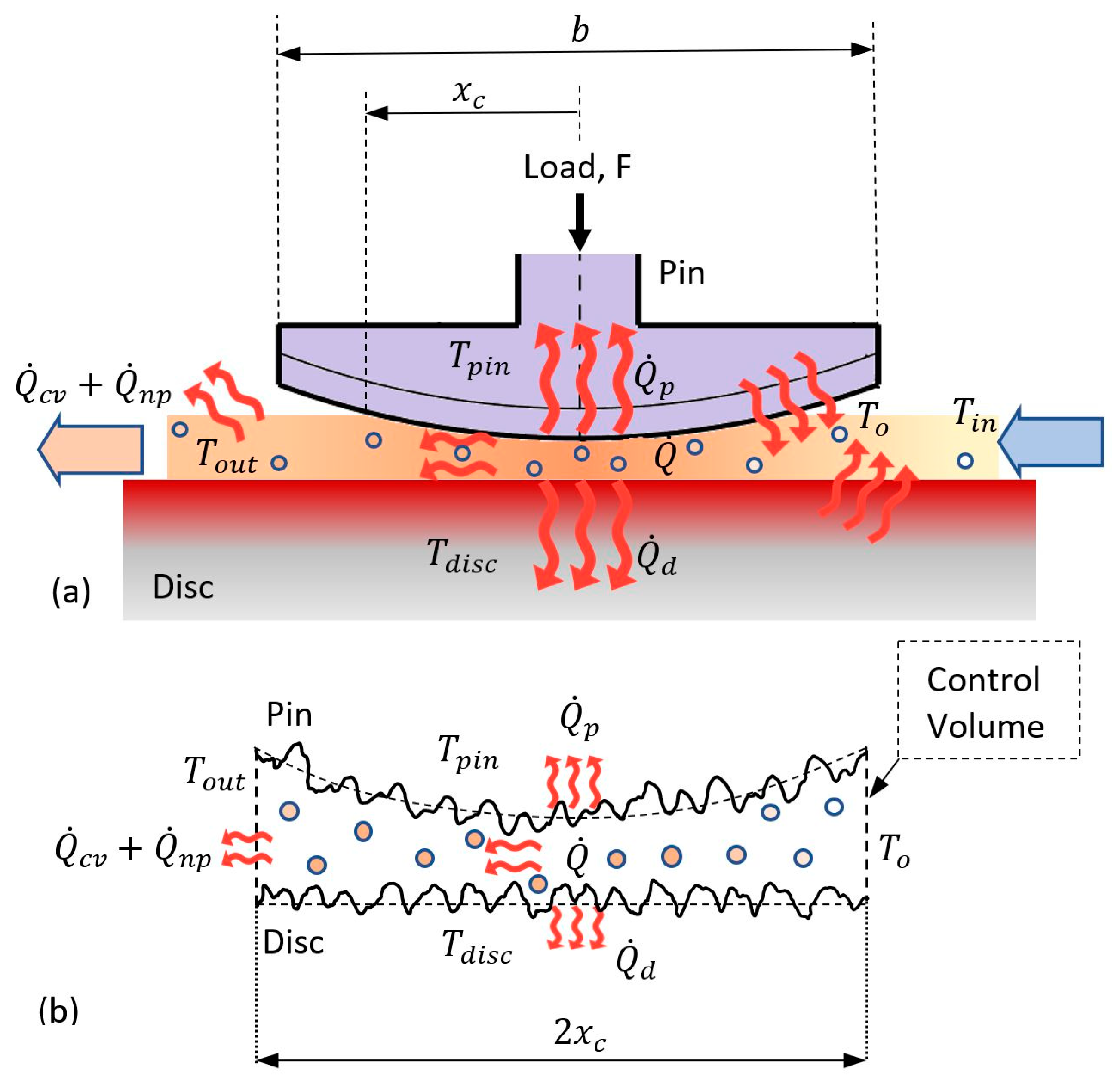
3.2. Thermal Analysis
A control volume thermal network model, similar to that proposed in [
57,
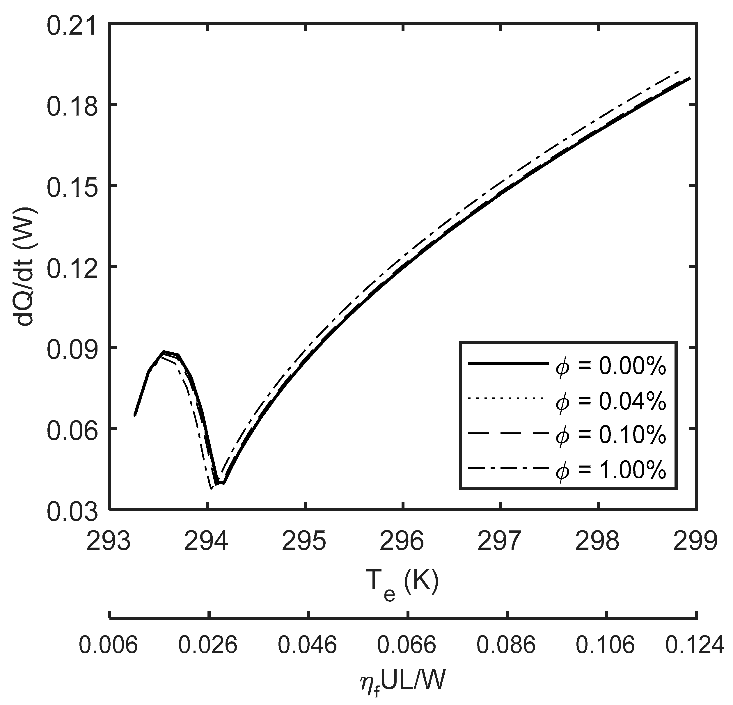
58], is used to develop an analytical thermal model for pin-disc conjunction. This model predicts the average contact temperature of the lubricant as well as the flash temperature of the contiguous contacting surfaces. Friction is regarded as the only source of heat generation, thus:
The generated heat is partly carried away from the contact by the flow of lubricant and nanoparticles (i.e.,
) and partly conducted through the contacting surfaces; the pin;
and the disc;
. Hence
Convection cooling through lubricant flow is obtained from Equation (17), where the mass flow rate is approximated as:
. Parameters
and
are lubricant density and cross-section of lubricant flow, respectively. The mass flow rates of the lubricant and nanoparticles are determined as
and
respectively, thus:
where
,
,
and
are the effective lubricant contact temperature, nanoparticles temperature, and heat capacities for lubricant and nanofluid, respectively.
The lubricant temperature
initially rises to a temperature
at the inlet conjunction due to the heat flux from the solid boundaries [
57], thus
where the subscripts
d and
p refer to the disc and pin surfaces, respectively.
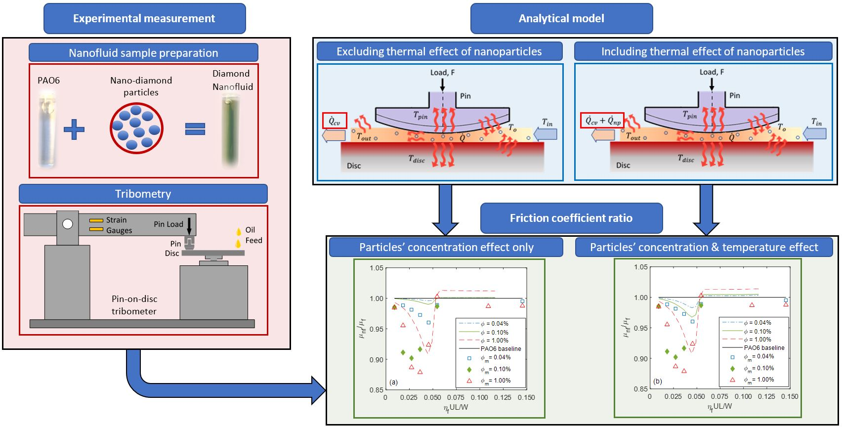
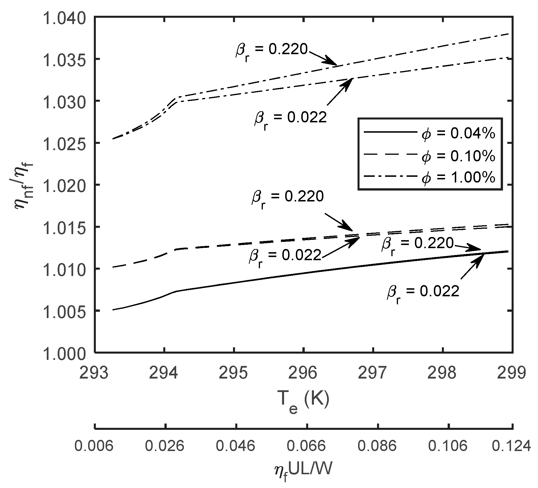
The variation of lubricant density,
, with temperature is taken into account through theuse of Equation (19). The coefficient of thermal expansion is denoted as
for the lubricant and
is the fluid density at a reference temperature (
). The density,
, and specific heat capacity,
, of nanofluids are calculated using the thermal properties of their constituent base lubricant and the diamond nanoparticles, as well as the volumetric concentration of nanoparticles,
, [
9]:
The generated heat at the center of the contact is transferred through a series of thermal-resistive barriers. These thermal resistors are: the lubricant film;
, boundary layer convection;
and surface flash thermal conduction;
. The analogy of lubricant flow to a laminar flow through a tube is used to determine these resistances. The parameters
,
,
and
are the heat transfer coefficient of the boundary layer, thermal conductivity of lubricant film, thermal conductivity of solid surfaces and the characteristic length for flash temperature and are defined as follows:
Detailed calculation of these parameters is provided in [
57,
58,
59]. The thermal conductivity of nanofluids,
, is estimated using the modified Maxwell’s theory to include the effects of particle shape and size, as well as the contiguous nanolayer of fluid about the particle [
58,
60]:
Shape parameter,
is considered to be equal to
, where
is the sphericity factor. It is the ratio of the surface area of a sphere, with its volume equal to that of the nanoparticle, to the actual surface area of the particle. The shape parameter,
for perfectly spherical particles. A solid-like nanolayer of fluid molecules forms on the surface of particles due to Brownian motion and physisorption-chemisorption effects [
61]. The thickness of this nanolayer is suggested to be up to 3 molecular layers of the base fluid [
62]. Dolatabadi et al. [
61] showed that the molecular stacking in the nanolayer is driven by the progressive adsorption-desorption process, utilizing Arrhenius and BET (Brunauer–Emmett–Teller) theories. The thickness of nanolayer,
, can be determined using:
where
is the reaction rate ratio of adsorption to desorption.
and
are the equilibrium pressure of adsorbates at the adsorption temperature and the pressure of the bulk lubricant above the last layer of adsorbate respectively. This method proposes that five molecular layers of PAO6 will form on the surface of diamond nanoparticles and the sixth layer will reach equilibrium with only 55% surface coverage. Parameter
is the ratio of the thickness of nanolayer with respect to the nanoparticle’s radius (
). This solid-like nanolayer has higher thermal conductivity than that of the base fluid. The equivalent thermal conductivity of the suspended nanoparticle,
, equals the combined thermal conductivity of nanoparticle and its contiguous nanolayer:
where
.
and
are the thermal conductivities of nanolayer and nanoparticle respectively. Yu and Choi [
60] assumed that
; thus,
. Using a similar approach to that of Morris et al. [
57], the average contact temperature is predicted using Equation (26). The average contact temperature is not representative of the flash temperature of the asperities. The heat conduction through asperity pairs are neglected since the asperity area of contact is typically less than 1–5% of the total contact area [
57]. The thermal resistance due to convection of lubricant is
and the resistance due to the heat transfer of nanoparticles is:
. Therefore, the effective average contact temperature becomes
where
shows the product of thermal resistances of contacting surfaces and
. Thus, the temperature rise of the counter face surfaces can also be predicted as
The tribological contact model is solved numerically. An initial guess for the film thickness is made, using Equation (4). The hydrodynamic and asperity contact loads are obtained iteratively (i.e., contact reaction:
). The following load convergence criterion is used:
where
F is the applied pin load. If the criterion is not satisfied, then the film thickness is adjusted and the entire procedure is repeated; i.e.,
where
is the under-relaxation factor in this case.
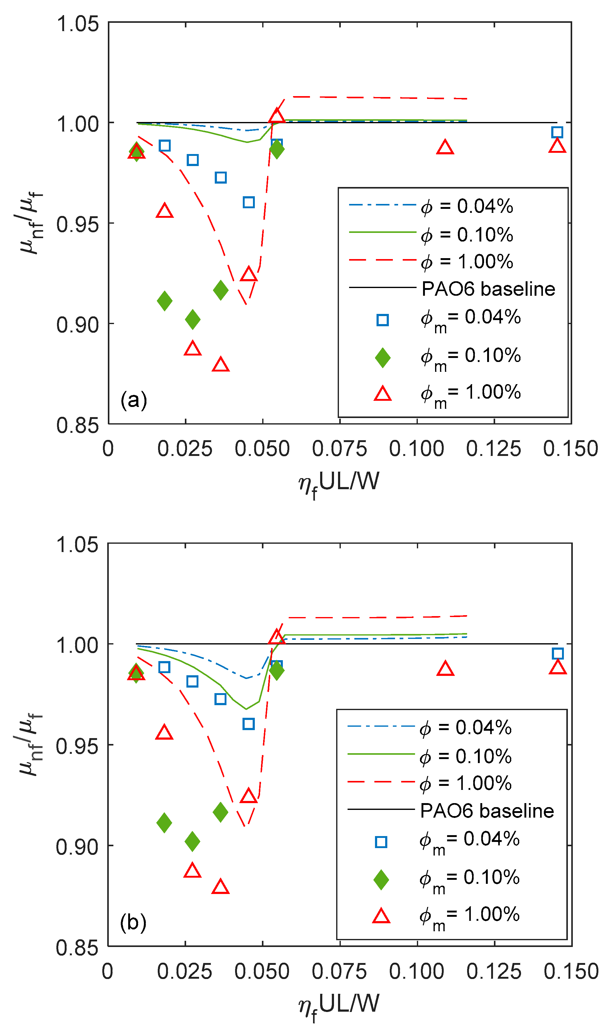
Thus, the coefficient of friction is predicted as: . This depends on the nanofluids used. Therefore, for the base PAO6 lubricant the coefficient of friction is denoted by and for any nanofluid, comprising the PAO6 lubricant with a volume fraction of nanoparticles is denoted by . All coefficients of friction were also directly measured by the tribometer as well.


