High Temperature Tribology under Linear Oscillation Motion

 ,
, 

Abstract
1. Introduction
2. Background
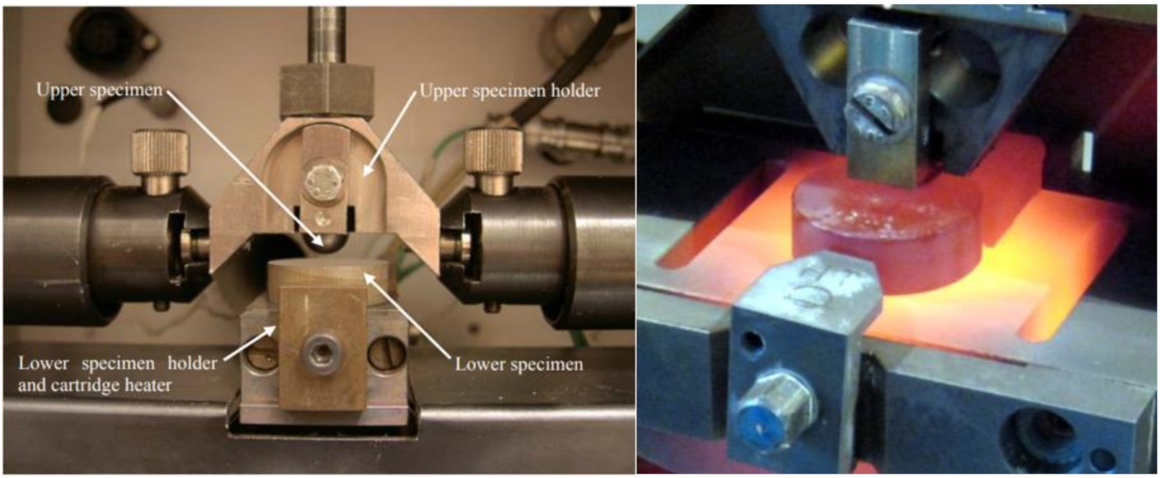
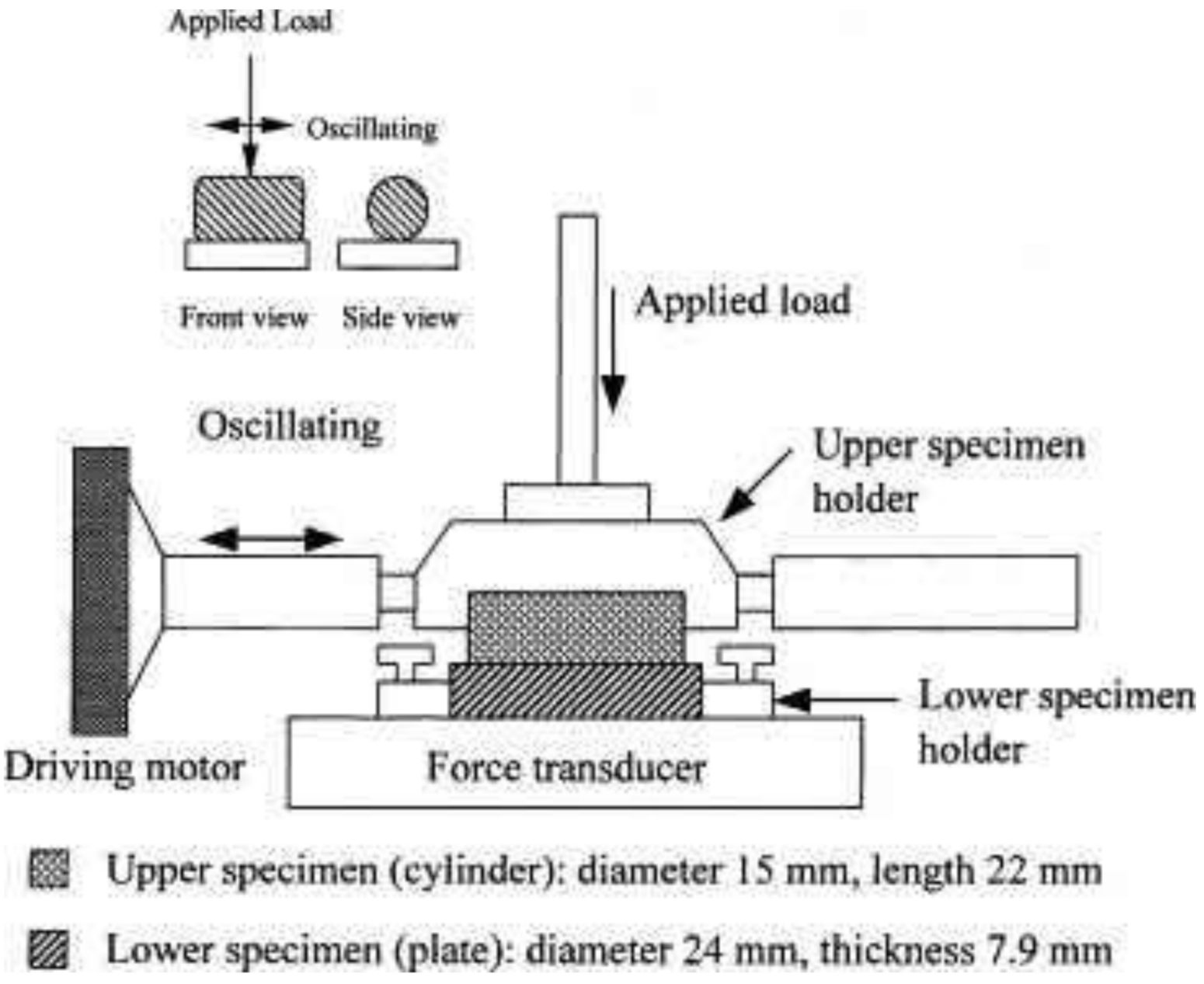
3. Tribometer for High Temperature Applications
4. Purpose and Methodology
5. Experimental Comparisons
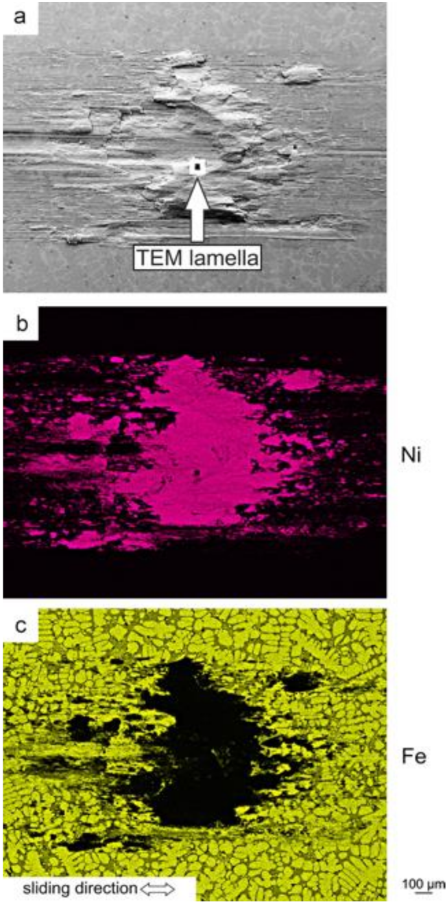
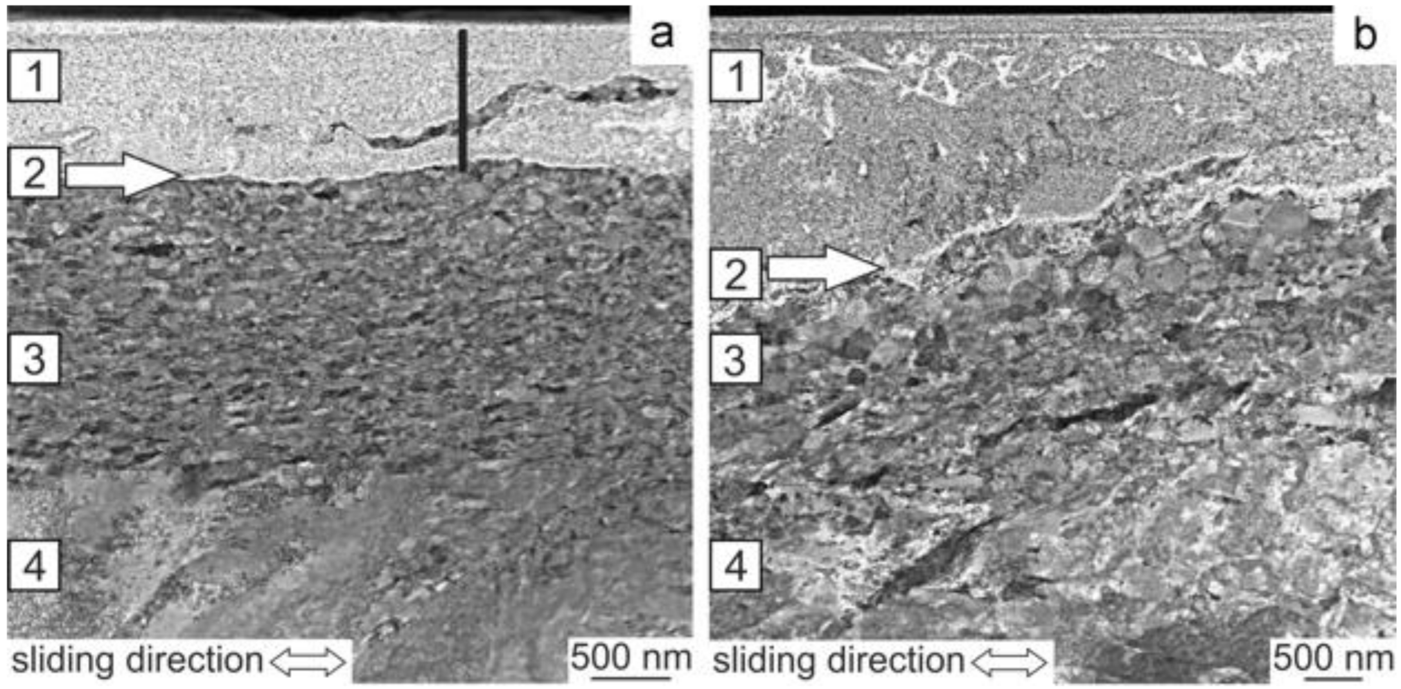
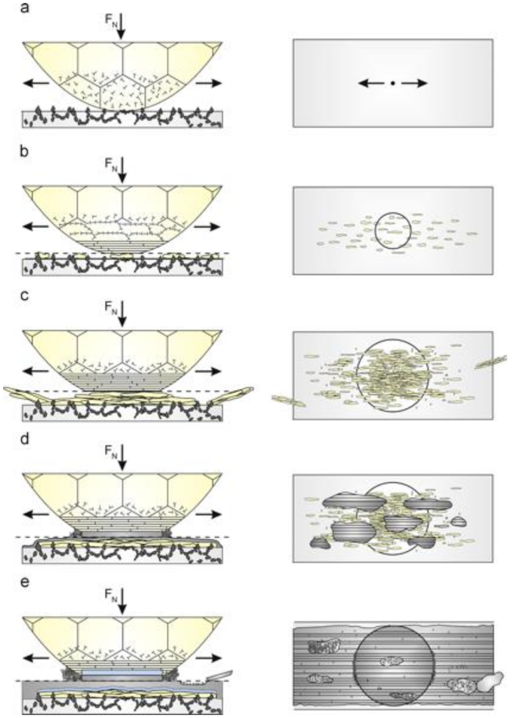
5.1. Tribolayers
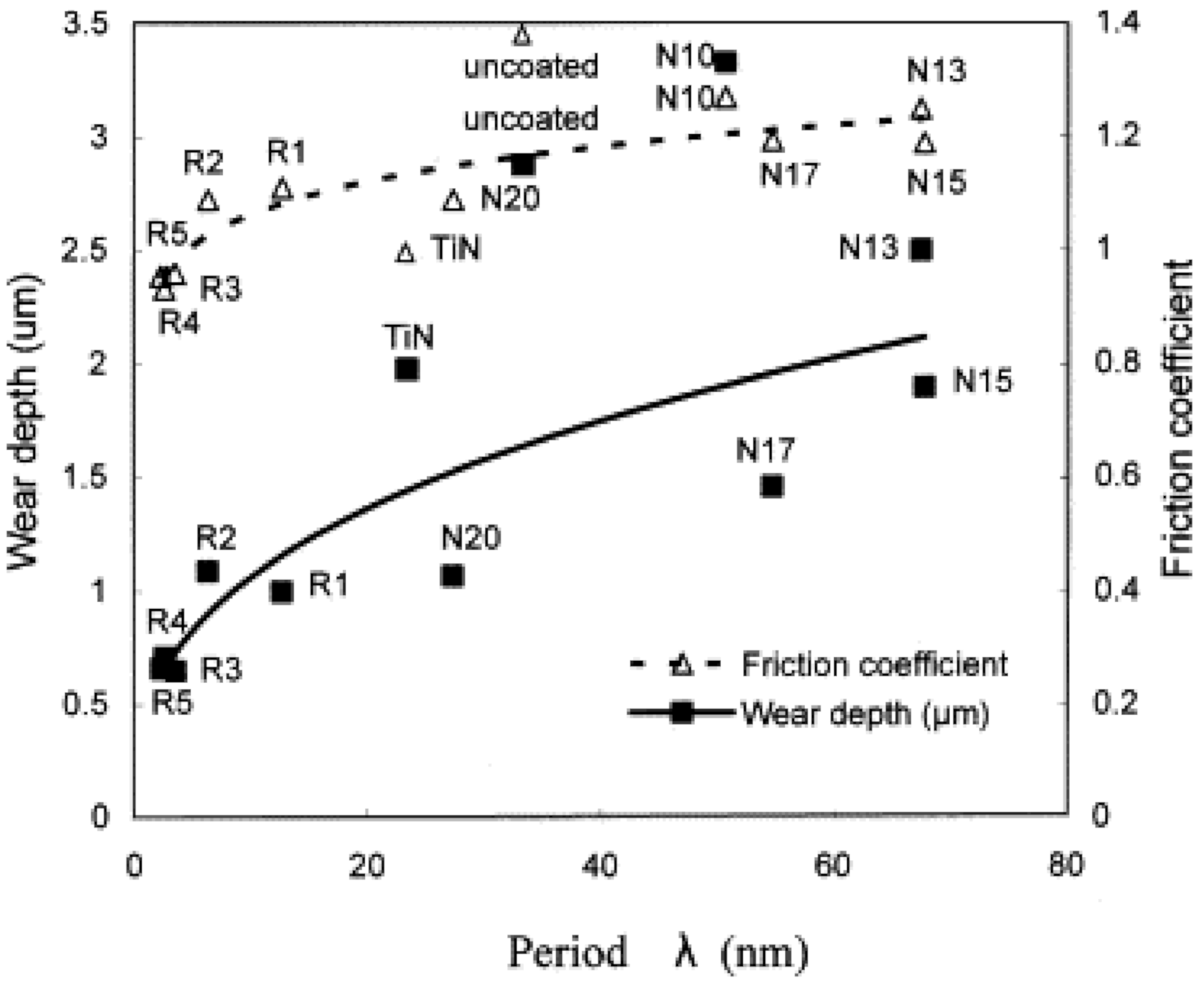
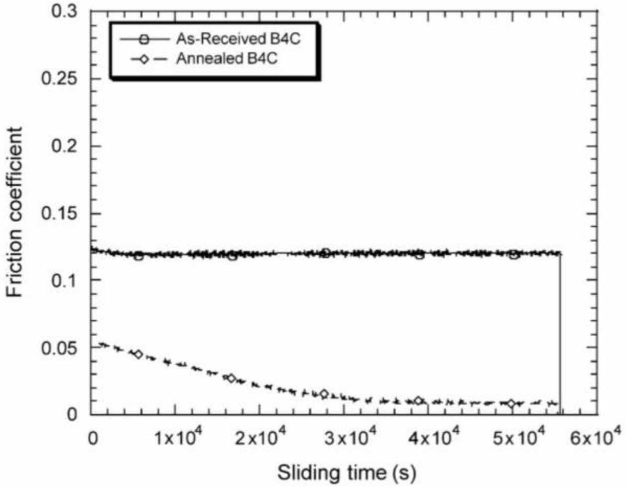
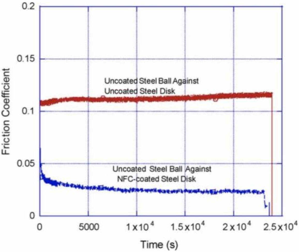
5.2. Coating
5.3. Brake Materials
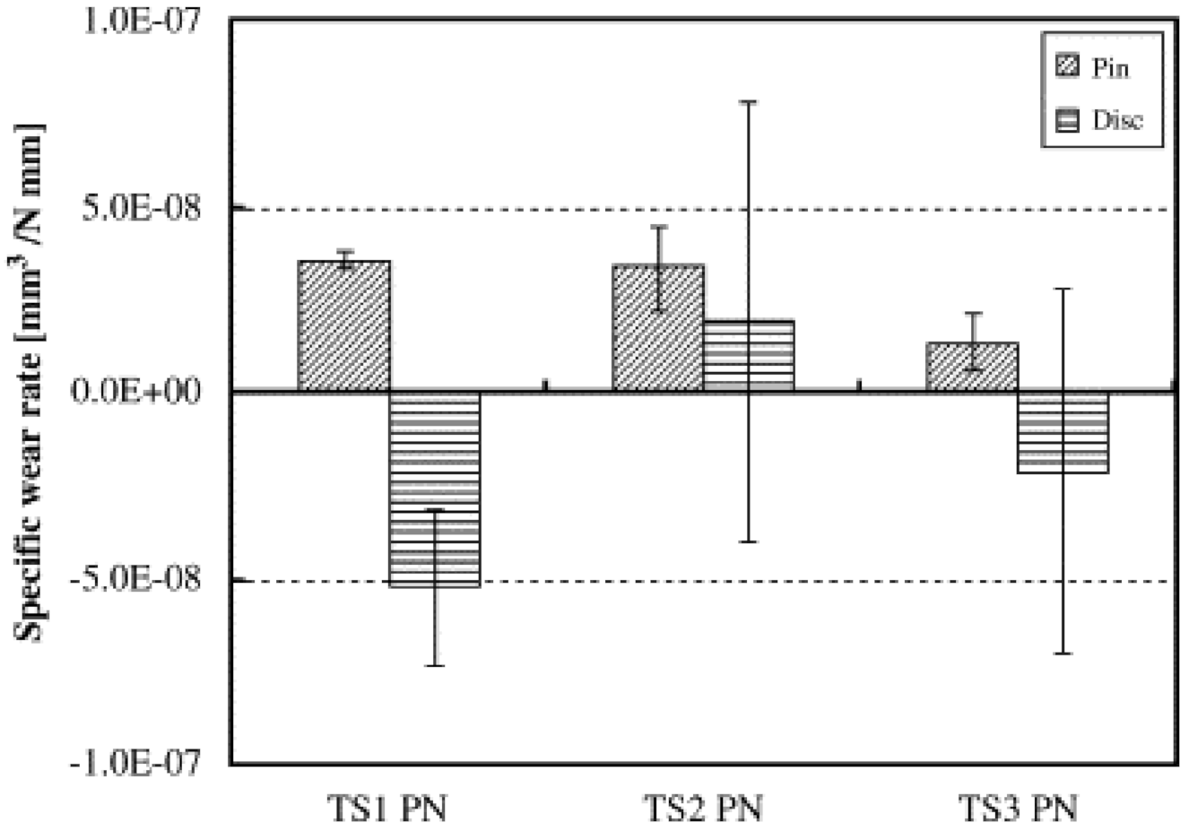
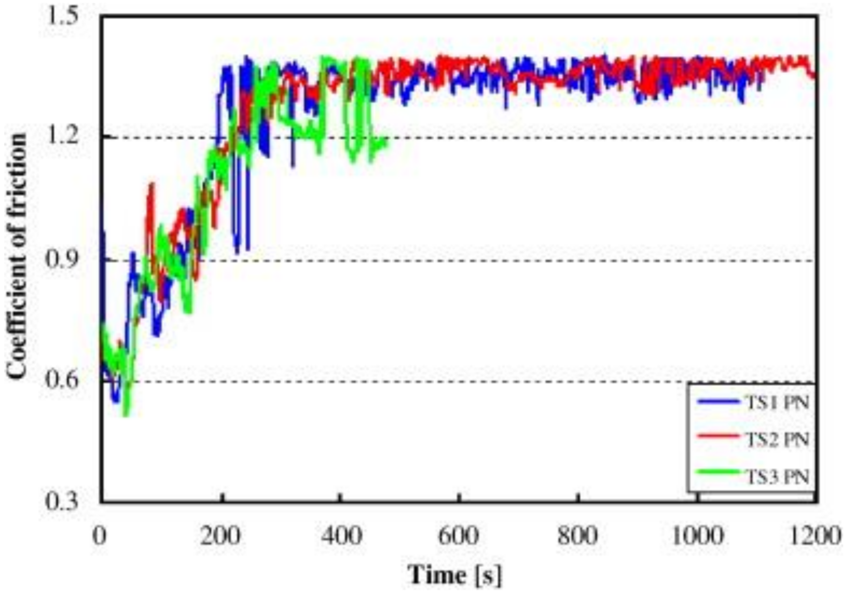
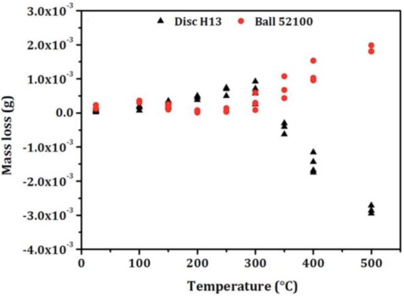
5.4. Tool Steels
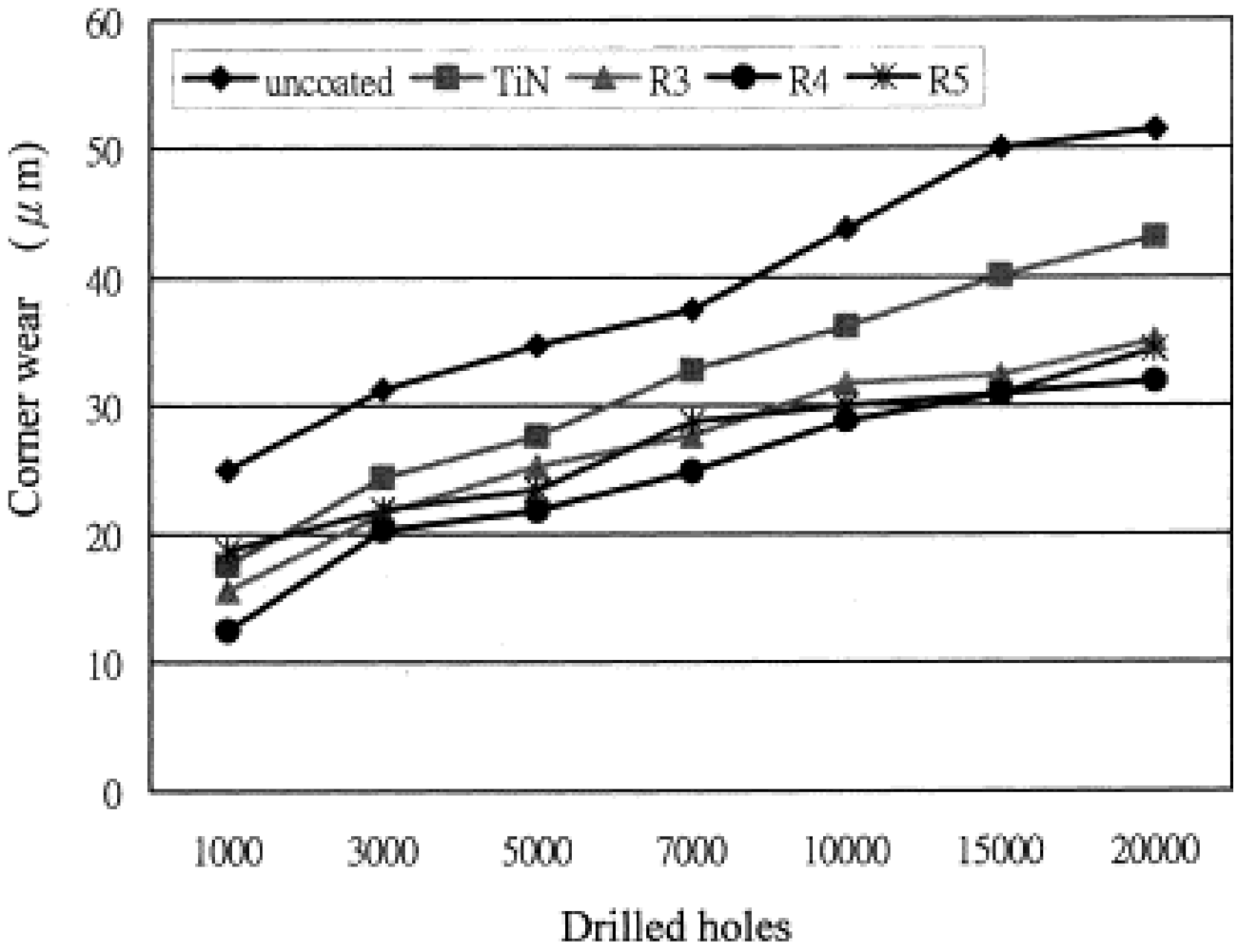
5.5. Drilling
5.6. Additional Literature
5.6.1. More SRV Applications/Tests
5.6.2. Tribological Advancements/Discoveries
6. Conclusions
Author Contributions
Funding
Conflicts of Interest
References
- Woydt, M. Materials based concepts for an oil free engine. In New Directions in Tribology; Hutchings, I.M., Ed.; First World Tribology Congress: London, UK, 1997; pp. 459–468. ISBN 1-86058-099-8. [Google Scholar]
- Rynio, C.; Hattendorf, H.; Klöwer, J.; Eggeler, G. The evolution of tribolayers during high temperature sliding wear. Wear 2014, 315, 1–10. [Google Scholar] [CrossRef]
- Durango, A.Z.; Cano, M.F.; Souza, R.M.; Sinatora, A. Effect of temperature on friction and wear under reciprocating sliding of AISI 52100 against AISI H13 steel. Mater. Perform. Charact. 2020, 9, 365–378. [Google Scholar] [CrossRef]
- Lewis, R.; Dwyer-Joyce, R.S. Combating Automotive Engine Valve Recession: A Case Study. Tribol. Lubr. Technol. 2003, 59, 48–51. [Google Scholar]
- Alvi, S.A.; Akhtar, F. High temperature tribology of polymer derived ceramic composite coatings. Sci. Rep. 2018, 8, 15105. [Google Scholar] [CrossRef] [PubMed]
- Woydt, M. Review on Lubricious Oxides and Their Practical Importance. In Handbook of Surface Modifications and Processing: Physical & Chemical Tribological Methodologies; Totten, G.E., Ed.; Marcel Dekker: New York, NY, USA, 2004; ISBN 0-9247-4872-7. [Google Scholar]
- Hardell, J. High Temperature Tribology of High Strength Boron Steel and Tool Steels. Ph.D. Thesis, Luleå University of Technology, Luleå, Sweden, June 2017. Available online: http://epubl.ltu.se/1402-1757/2007/36 (accessed on 13 July 2020).
- Mu, Y.; Wang, B.; Huang, M.; Zhou, J.; Li, X. Investigation on tribological characteristics of boron steel 22MnB5–tool steel H13 tribopair at high temperature. Proc. Inst. Mech. Eng. Part J J. Eng. Tribol. 2017, 231, 165–175. [Google Scholar] [CrossRef]
- Stott, F.H. High-temperature sliding wear of metals. Tribol. Int. 2002, 35, 489–495. [Google Scholar] [CrossRef]
- Chang, Y.N.; Wei, F.I. High temperature oxidation of low alloy steels. J. Mater. Sci. 1989, 24, 14–22. [Google Scholar] [CrossRef]
- Stott, F.H. The influence of oxidation on the wear of metals and alloys. In New Directions in Tribology; Hutchings, I.M., Ed.; First World Tribology Congress: London, UK, 1997; pp. 391–401. ISBN 1-86058-099-8. [Google Scholar]
- Gardos, M.N. Magnéli phases of anion-deficient rutile as lubricious oxides. Part I. Tribological behavior of 276 single-crystal and polycrystalline rutile (TinO2n−1). Tribol. Lett. 2000, 8, 65–78. [Google Scholar] [CrossRef]
- Woydt, M. Sub-stoichiometric Oxides for Wear Resistance. Wear 2019, 438, 203104. [Google Scholar] [CrossRef]
- Hardell, J.; Hernandez, S.; Mozgovoy, S.; Pelcastre, L.; Courbon, C.; Prakash, B. Effect of oxide layers and near surface transformations on friction and wear during tool steel and boron steel interaction at high temperatures. Wear 2015, 330, 223–229. [Google Scholar] [CrossRef]
- Wallace, F.J.; Wordsworth, R.A.; Dowson, D.; Lansdown, A.R.; Alexander, W.; Reiter, H. US Army Workshop on Low Heat Rejection Engines (4th); Leeds University: Leeds, UK, 1989. [Google Scholar]
- Beadling, A.R.; Bryant, M.G.; Dowson, D.; Neville, A. A link between the tribology and corrosive degradation of metal-on-metal THRs. Wear 2017, 113, 354–361. [Google Scholar] [CrossRef]
- Zhang, S.Y.; Feng, S.S. Friction and wear performances of brake material dry sliding against a composite with a semi-interpenetrating network structure of ceramics and Al-alloy. Tribol. Int. 2011, 44, 248–257. [Google Scholar] [CrossRef]
- Hardell, J.; Prakash, B. High-temperature friction and wear behaviour of different tool steels during sliding against Al-SI-coated high-strength steel. Tribol. Int. 2008, 41, 663–671. [Google Scholar] [CrossRef]
- Yao, S.H.; Kao, W.H.; Su, Y.L.; Liu, T.H. On the tribology and micro-drilling performance of TiN/AlN nanolayer coatings. Mater. Sci. Eng. A 2004, 386, 149–155. [Google Scholar] [CrossRef]
- Woydt, M. Application oriented tribological test concepts. Lube Tech. 2017, 130, 22–28. [Google Scholar]
- Obert, P.; Müller, T.; Füßer, H.J.; Bartel, D. The influence of oil supply and cylinder liner temperature on friction, wear and scuffing behavior of piston ring cylinder liner contacts—A new model test. Tribol. Int. 2016, 94, 306–314. [Google Scholar] [CrossRef]
- Woydt, M.; Ebrecht, J. Testing friction and wear of the tribosystem piston ring and cylinder liner outside of engines. Lubr. Sci. 2008, 14, 113–126. [Google Scholar] [CrossRef]
- Podgornik, B.; Vižintin, J. Tribology of thin films and their use in the field of machine elements. Vacuum 2002, 68, 39–47. [Google Scholar] [CrossRef]
- Mano, H.; Ohana, T. Evaluation of anti-adhesion characteristics of diamond like carbon film using reciprocating ball-on-plate tribometer. Wear 2017, 386, 188–194. [Google Scholar] [CrossRef]
- Schneider, A.; Steinmueller-Nethl, D.; Roy, M.; Franek, F. Enhanced tribological performances of nanocrystalline diamond film. Int. J. Refract. Met. Hard Mater. 2010, 28, 40–50. [Google Scholar] [CrossRef]
- Thoma, M. High Wear Resistance at High Temperatures by a Co + Cr2O3 Electrodeposited Composite Coating. In Proceedings of the 4th International Tribology Symposium, Eurotrip 85: IV; Elsevier: Lyon, France, 1985. [Google Scholar]
- Kayaba, T.; Iwabuchi, A. The fretting wear of 0.45% C steel and austenitic stainless steel from 20 to 650 °C in air. Wear 1981, 74, 229–245. [Google Scholar] [CrossRef]
- Rybiak, R.; Fouvry, S.; Bonnet, B. Fretting wear of stainless steels under variable temperature conditions: Introduction of a ‘composite’ wear law. Wear 2010, 268, 413–423. [Google Scholar] [CrossRef]
- Hurricks, P.L. The fretting wear of mild steel from room temperature to 200 °C. Wear 1972, 19, 207–229. [Google Scholar] [CrossRef]
- Hurricks, P.L. The mechanism of fretting—A review. Wear 1970, 15, 389–409. [Google Scholar] [CrossRef]
- Taylor, D.E.; Hardisty, F.B.; Waterhouse, R.B.; Nehru, A.Y. The fretting wear of an austenitic stainless steel in air and in carbon dioxide at elevated temperatures. Wear 1979, 56, 9–18. [Google Scholar] [CrossRef]
- Rustamov, I.; Wang, Y.; Wang, Z. Triple Heat Treatment Effects on the Microstructure and Fretting Wear Behavior of Inconel X-750 Alloy. In Proceedings of the 46th Leeds-Lyon Symposium on Tribology, Lyon, France, 2–4 September 2019. [Google Scholar]
- Jacobs, C. Worries over Fretting Wear. Lubesngreases. Available online: https://www.lubesngreases.com/magazine/worries-over-fretting-wear/ (accessed on 1 October 2020).
- Erdemir, A. Review of engineered tribological interfaces for improved boundary lubrication. Tribol. Int. 2005, 38, 249–256. [Google Scholar] [CrossRef]
- Erdemir, A. Solid lubricants and self-lubricating films. In Modern Tribology Handbook; Bhushan, B., Ed.; CRC Press: Boca Raton, FL, USA, 2001; pp. 787–818. [Google Scholar]
- Holmberg, K.; Ronkainen, H.; Matthews, A. Tribology of thin coatings. Ceram. Int. 2000, 26, 787–795. [Google Scholar] [CrossRef]
- Hogmark, S.; Jacobson, S.; Larsson, M.; Wiklund, U. Mechanical and tribological requirements and evaluation of coating composites. In Modern Tribology Handbook; Bhushan, B., Ed.; CRC Press: Boca Raton, FL, USA, 2001; pp. 931–959. [Google Scholar]
- Wang, H.D.; Zhuang, D.M.; Wang, K.L.; Liu, J.J. Comparison of the tribological properties of an ion sulfurized coating and a plasma sprayed FeS coating. Mater. Sci. Eng. A 2003, 357, 321–327. [Google Scholar]
- Julthongpiput, D.; Ahn, H.S.; Sidorenko, A.; Kim, D.I.; Tsukruk, V.V. Towards self-lubricated nanocoatings. Tribol. Int. 2002, 35, 829–836. [Google Scholar] [CrossRef]
- Erdemir, A.O.; Ajayi, O.O.; Fenske, G.R.; Erck, R.A.; Hsieh, J.H. Synergistic effects of solid and liquid lubrication on the tribological behavior of transformation—Toughened ZrO2 ceramics. Tribol. Trans. 1992, 35, 287–292. [Google Scholar] [CrossRef]
- Erdemir, A.; Erck, R.A.; Fenske, G.R.; Hong, H. Solid/liquid lubrication of ceramics at elevated temperature. Wear 1996, 203, 588–594. [Google Scholar] [CrossRef]
- Erdemir, A. Tribological properties of boric acid and boric-acid-forming surfaces: Part 1, crystal chemistry and mechanism of self-lubrication of boric acid. Lubr. Eng. 1991, 47, 168–172. [Google Scholar]
- Erdemir, A.; Eryilmaz, O.L.; Fenske, G. Synthesis of diamondlike carbon films with superlow friction and wear properties. J. Vac. Sci. Technol. 2000, 18, 1987–1992. [Google Scholar] [CrossRef]
- Gahlin, R.; Larsson, M.; Hedenqvist, P. ME-C: H coatings in motor vehicles. Wear 2001, 249, 302–309. [Google Scholar] [CrossRef]
- Podgornik, B.; Jacobson, S.; Hogmark, S. Influence of EP and AW additives on the tribological behaviour of hard low friction coatings. Surf. Coat. Technol. 2003, 165, 168–175. [Google Scholar] [CrossRef]
- Yasuda, Y.; Kano, M.; Mabuchi, Y.; Abou, S. Research on Diamond-like Carbon Coatings for Low-Friction Valve Lifters; SAE Paper No. 2001-03P-352; SAE International: Warrendale, PA, USA, 2003. [Google Scholar]
- Veprek, S. New developments in superhard coatings: The superhard nanocrystalline—Amorphous composites. Thin Solid Film. 1998, 317, 449–454. [Google Scholar] [CrossRef]
- Musil, J.; Vlcek, J. Magnetron sputtering of hard nano-composite coatings and their properties. Surf. Coat. Technol. 2001, 142, 557–566. [Google Scholar] [CrossRef]
- Dumitru, G.; Romano, V.; Weber, H.P.; Pimenov, S.M.; Kononenko, T.M.; Hermann, J. Laser treatment of tribological DLC films. Diamond Relat. Mater. 2003, 12, 1034–1040. [Google Scholar] [CrossRef]
- Dumitru, G.; Romano, V.; Weber, H.P.; Pimenov, S.; Kononenko, T.; Sentis, M. Femtosecond laser ablation of diamond-like carbon films. Appl. Surf. Sci. 2004, 222, 226–233. [Google Scholar] [CrossRef]
- Morales, S.T. Method to Improve Solid Lubricant Film Tribological Performance and Adhesion to Hot Forming Material. Patent No. US8250890 B2, 28 August 2012. [Google Scholar]
- Vergne, C.; Boher, C.; Gras, R.; Levaillant, C. Influence of oxides on friction in hot rolling: Experimental investigations and tribological modelling. Wear 2006, 260, 957–975. [Google Scholar] [CrossRef]
- Felder, E. Modes of wear and damage of hot rolling rolls. Relationships with thermomechanical characteristics of calamines. Rev. Met. 1984, 12, 931–942. [Google Scholar] [CrossRef]


| Test Parameters | Temperature (°C) | Sliding Velocity (mm/s) | Contact Pressure (Mpa) | Lubrication Condition |
|---|---|---|---|---|
| Temperature tests | 650, 750, 850 | 50 | 8 | Dry |
| Sliding velocity test | 750 | 25, 50, 75 | 8 | Dry |
| Contact pressure test | 750 | 50 | 4, 8 | Dry |
| Lubrication test | 750 | 50 | 8 | Dry, lubricated |
Publisher’s Note: MDPI stays neutral with regard to jurisdictional claims in published maps and institutional affiliations. |
© 2020 by the authors. Licensee MDPI, Basel, Switzerland. This article is an open access article distributed under the terms and conditions of the Creative Commons Attribution (CC BY) license (http://creativecommons.org/licenses/by/4.0/).
Share and Cite
Shah, R.; Chen, R.; Woydt, M.; Baumann, C.; Jurs, J.; Iaccarino, P. High Temperature Tribology under Linear Oscillation Motion. Lubricants 2021, 9, 5. https://doi.org/10.3390/lubricants9010005
Shah R, Chen R, Woydt M, Baumann C, Jurs J, Iaccarino P. High Temperature Tribology under Linear Oscillation Motion. Lubricants. 2021; 9(1):5. https://doi.org/10.3390/lubricants9010005
Chicago/Turabian StyleShah, Raj, Rui Chen, Mathias Woydt, Christoph Baumann, Joshua Jurs, and Philip Iaccarino. 2021. "High Temperature Tribology under Linear Oscillation Motion" Lubricants 9, no. 1: 5. https://doi.org/10.3390/lubricants9010005
APA StyleShah, R., Chen, R., Woydt, M., Baumann, C., Jurs, J., & Iaccarino, P. (2021). High Temperature Tribology under Linear Oscillation Motion. Lubricants, 9(1), 5. https://doi.org/10.3390/lubricants9010005