Article

Synthesis and Morphological Characterization of Electroless-Deposited Ni-P Coatings on Diamond Abrasives

1
J. Mike Walker ′66 Department of Mechanical Engineering, Texas A&M University, College Station, TX 77843-3123, USA
2
Department of Material Science and Engineering, Texas A&M University, College Station, TX 77843-3123, USA
3
Advanced Light Source, Lawrence Berkeley National Laboratory, 1 Cyclotron Rd, Berkeley, CA 94720, USA
4
Department of Engineering Technology and Industrial Distribution, Texas A&M University, College Station, TX 77843-3123, USA
*
Author to whom correspondence should be addressed.
Lubricants 2021, 9(2), 20; https://doi.org/10.3390/lubricants9020020
Submission received: 25 December 2020 / Revised: 30 January 2021 / Accepted: 9 February 2021 / Published: 20 February 2021

Abstract

:
Deposition of a coating on rough surfaces faces unique challenges due to the complexity of substrate morphology. In the present research, electroless deposition of a Ni-P coating was successfully deposited on diamond particles. Microtomography was conducted to study the deposition mechanisms. It revealed that the coating coverage rate on diamond particles was affected by the synergistic action of the deposition time, substrate morphology, and hypophosphite concentration. The best coverage was achieved in a solution with 0.2 mol/L hypophosphite. Two major morphological features of the coating: nodular and smooth, were influenced by the deposition parameters, coating integrity, and substrate morphology. The failure was seen in fractured and peeled off coatings. It was due to residual stress produced by the coalescing of crystallites during the deposition. This failure mechanism explains the tendency of coating fracture at three morphological features of the substrate. This work is beneficial to semiconductor manufacturing where effective cutting in chip fabrication is essential.

1. Introduction

Electroless deposition is the process of metalizing a surface in the absence of an external electrical source. It has been adopted as a simple and cost-effective method to synthesize Ni-P coatings on various substrates [1]. The electroless Ni-P coating has many advantages, such as good mechanical, magnetic, tribological, and electrochemical properties. It has been widely used for corrosion-resistant and wear-resistant coatings. Electroless deposition is also suitable to deposit films on complex geometric surfaces such as through-holes and blind recesses (vias) in the printed circuit board due to its uniform thickness, good solderability, and ability to deposit on non-conductive materials. This deposition method has also been implemented to metalize the interconnects for ultra-large-scale integration (ULSI) technology [2,3,4,5]. Electroless deposition of ternary and quaternary alloys [6,7,8,9,10] and metal-ceramic composite [11,12,13,14,15] or metal-polymer composites [16,17,18] are also under the spotlight of current research because of the unique and tunable properties of the deposited materials.
The electroless Ni-P-coated abrasives have been used to manufacture machining tools. Coated abrasives such as coated diamond particles can effectively increase holding force between the abrasive particles and the matrix, reduce thermal shock, improve heat dissipation, and protect the diamond from oxidation or graphitization in high-speed cutting. Therefore, coated abrasives are a better choice for electroplated and polymer-bonded tools [19,20,21]. However, the issue of coating fracture and detaching from the substrate is causing inconsistency in product quality. For example, the diamond wire saw used to slice silicon wafers must provide consistent cuts to achieve quality chips. A test method of the coating’s resistance to degradation in the electroplating environment has been reported. It was found that the pinholes formed during the deposition process by hydrogen evolution cause the weakening of the mechanical strength of the coating and make the coating susceptible to corrosion [22].
The coating microstructures and properties are influenced by many factors in the deposition process, including the composition and concentration of the plating bath, the pH, plating temperature, agitation conditions, pretreatment, and post-treatment [23]. The precise control of coatings is difficult because the electroless deposition is a complex heterogeneous catalytic process at the solid–liquid interface. It involves multiple interactions between reactant ions and other ions and molecules in the solvent. Besides, when the substrate is immersed in the solution, the electrostatic layer near the solid–liquid interface affects the distribution and behaviors of ions in its vicinity [24]. Therefore, the deposition kinetics of the electroless deposition process are not fully developed.
The characterization of coatings on abrasives has been a challenging issue. For example, the traditional adhesion test performed by pulling off a piece of coating from the substrate is impossible for coatings on diamond grits. Besides, due to the free movement of the particle in the deposition process, the in-situ study of morphology evolution of the electroless plating is impossible.
X-ray tomography is a powerful, non-destructive method to image the internal structure of a sample across length scales spanning orders of magnitude [25]. X-ray tomography of the Ni-P-coated diamond abrasives allows us to see both the morphology of coating and the surface morphology of the substrate that the coatings are grown on. Morphology change of the coating indicates the coating’s response to the different environments. Few people have studied the synergistic effect of substrate morphology and operation conditions on coating properties, which will be the focus of this study.
In this study, Ni-P coatings were electrolessly deposited on diamond particles and characterized by optical microscopy, scanning electron microscopy, and X-ray computed tomography techniques. The influence of deposition time, nickel metal to reducing agenting ratio, and substrate morphology on the coating coverage rate, coating morphology, and deposition kinetics have been investigated. The substrate morphological features which promote or inhibit coating failure were identified based on the morphology analysis. The underlying mechanisms of how the substrate morphologic features affect coating failure were discovered.

2. Materials and Methods

2.1. Pretreatment

The plating was performed on loose diamond grits of sizes ranging 400 to 600 µm (30–40 mesh). Before the electroless deposition, the substrate was pretreated to form Pd catalyst sites on the surface. The pretreatment process is sketched in Figure 1. The electrode with diamond substrates was cleaned in acetone and then immersed in 10 vol.% H2SO4 solution for pickling to remove organic and oxide. After this, the electrode was immersed in the SnCl2/HCl solution and PdCl2/HCl solution for sensitization and activation, respectively. The sensitization and activation details are shown in Table 1. The above pretreatment steps were all done at room temperature, and proper rinses were conducted between steps. The diamond particles are let dry in the air after the final rinse.

2.2. Electroless Deposition

Four different deposition solutions are made with varying concentrations of sodium hypophosphite, while the concentrations of other components are the same. The compositions of plating solutions are listed in Table 2. The molar ratios of nickel ion to reductant (hypophosphite ion) are 1:1, 1:2, 1:3, and 1:4 respectively, therefore the plating deposition solutions are denoted as Ni:P = 1:1, Ni:P = 1:2, Ni:P = 1:3, and Ni:P = 1:4. The pH values of all the solutions were adjusted to around 9 by NH4OH, and the deposition solutions were heated to 70 °C using a thermostatic bath.
For each plating bath, around 50 pretreated diamond grits were dropped in the plating bath of 3 mL. The estimated bath loading is about 1.3 dm2/L (0.53 ft2/gal). At deposition time of 5, 10, 20, 30, 60, and 180 min, several diamond grits were taken out from the solution and properly stored. The coated diamond particle samples were labeled as Ni:P = 1:1–5 min, Ni:P = 1:1–10 min, …, Ni:P = 1:4–180 min, to indicate both the plating bath deposition solution and the plating deposition time.

2.3. Morphological Characterizations

The surface morphology of the activated diamond surface was evaluated using an atomic force microscope (Nano-R2, Pacific Nanotechnology, Santa Clara, CA, USA) in non-contact mode to check the distribution of the palladium metal clusters. The Nanorule (Pacific Nanotechnology, Inc., Santa Clara, CA, USA) program was employed for analysis and image processing.
The morphology of coating on diamond particles was examined by a JEOL JSM-7500F ultra-high-resolution field emission scanning electron microscope (FE-SEM) and a tabletop digital microscope (Dino-Lite AM4113ZTS, Dino-Lite, Roanoke, VA, USA).
The synchrotron X-ray micro-computerized tomography experiments were conducted at Advanced Light Source (ALS) beamline 8.3.2, Lawrence Berkeley National Lab. The X-ray from the synchrotron source is filtered by a monochromator and selected energy level exit. Then, by opening the shutter, the monochromatic X-ray beam shines on the sample on a rotational stage. Some X-rays are absorbed by the sample, and the transmit X-ray is converted to visible light by a 50 µm LuAG scintillator. The visible light then goes through a 10× optical lens and is reflected by a mirror and captured by a PCO.Edge scientific CMOS camera (PCO, San Francisco, CA, USA) [26]. In this study, the imaging energy was in the range of 8 to 22 keV depending on the contrast of the image for different samples. The beam current is 500 mA. The exposure time was 200 ms for recording each projected image, and 1313 projections were taken by rotating the sample over 180°.
The cross-section image datasets were reconstructed by Xi-CAM software installed at the beamline (Lawrence Berkeley National Laboratory, Berkeley, CA, USA). The resolution of the reconstructed cross-section image is 0.641 µm per pixel for the abrasives in all three directions. The images generated by X-ray tomography were processed by three-dimensional (3D) Slicer software version 4.10.2 to view the coatings in 3-dimension. Through the processed tomography images, both the inner and outer surfaces of the coatings can be reviewed from any angle. ImageJ software was used for the dimension measurements for the images. Python codes were used to calculate the thickness of the coating after the adjustment of the image direction and selection of the proper brightness window of the images.

3. Results and Discussion

3.1. Coating Coverage Rate

The coating coverage rate is an important indicator to evaluate the effectiveness of the coating process on diamond particles. A high coating coverage rate is expected to protect the diamond substrate from oxidation or graphitization in a machining process using a diamond-metal composite tool [20]. In the electroplating process to make diamond tools, a continuous coating on the diamond particle can prevent exposure of the interfaces to the electrolyte. Therefore, the corrosion and erosion attack of electrolyte is less likely to strip off the coating [27]. In this section, we aim to find out how the various factors in the electroless deposition process influence the coating coverage rate.
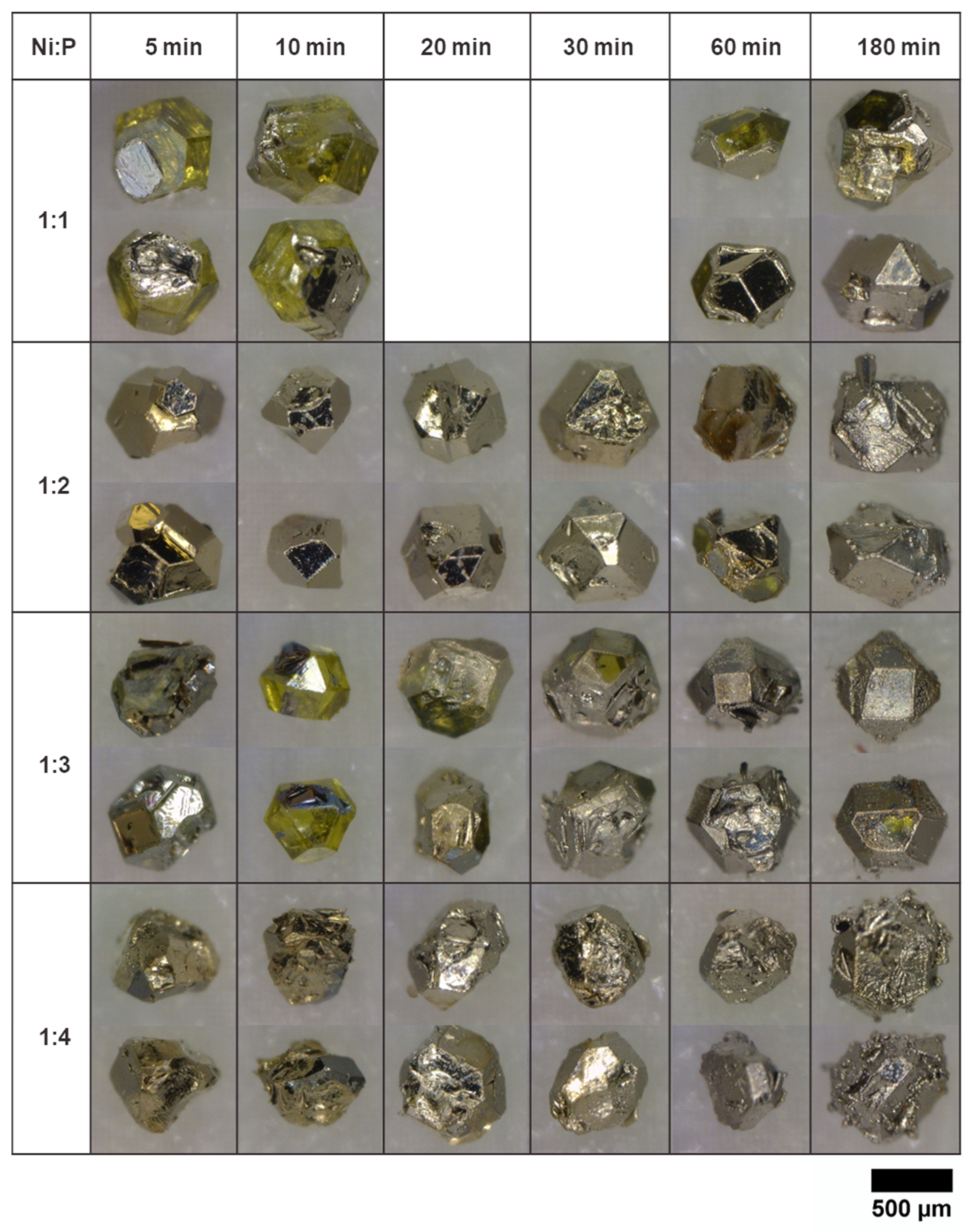
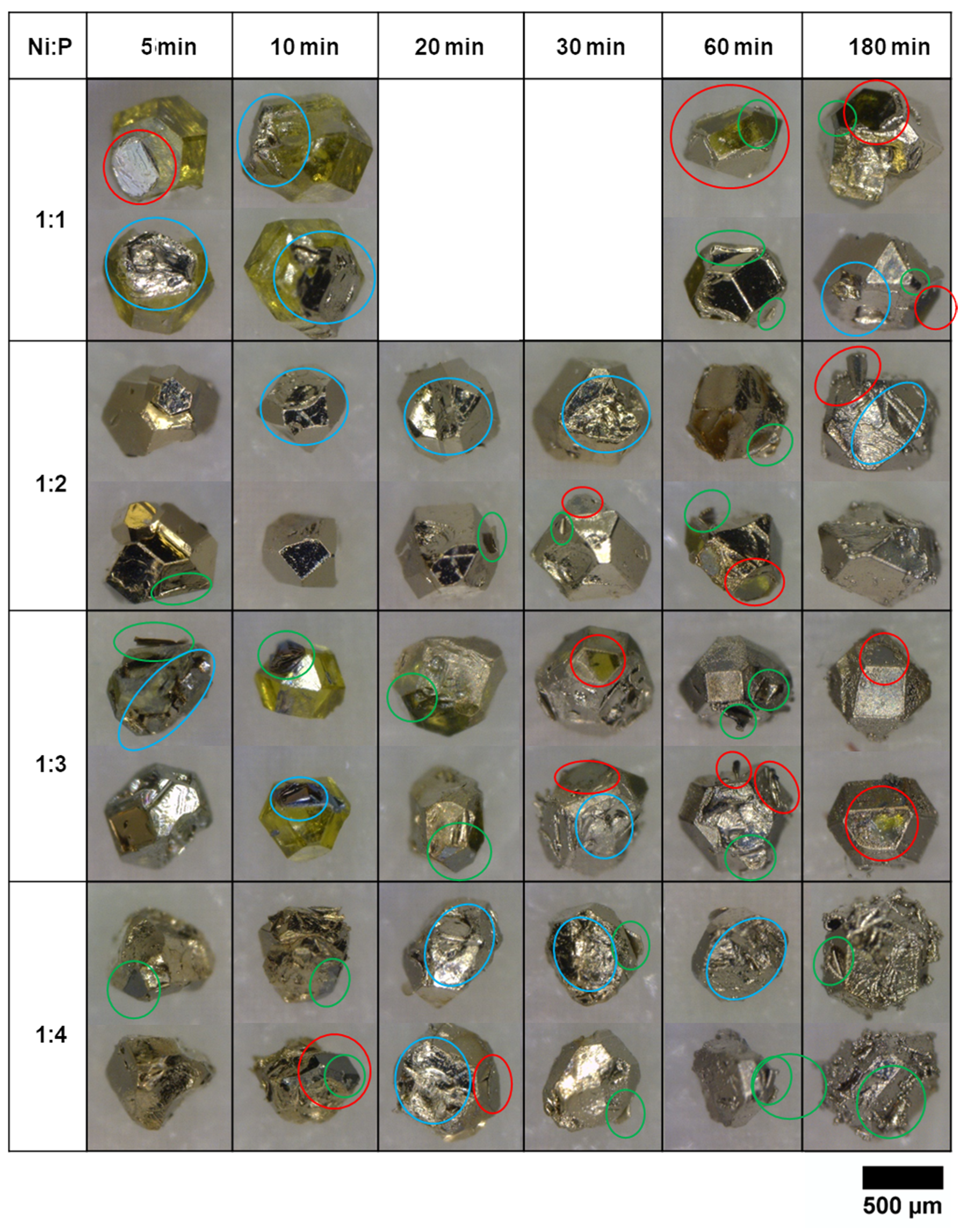
The coverage of a coating on the diamond particles can be observed from the optical images since the original diamond surface shows yellowish or greenish color. In contrast, the surface covered by coatings exhibits a shiny silver appearance. The correlation of the coverage rate with the initial reducing agent concentration and deposition time is evaluated. Therefore, the optical images of the coated diamond particles are arranged with these two parameters. The row labeled Ni:P = 1:1 presents the plating solution that was initially composed of 0.1 mol/L NiSO4 (same for all the solutions) and 0.1 mol/L NaH2PO2. During the deposition in each plating bath, diamond particles were sampled at six different deposition times: 5, 10, 20, 30, 60, and 180 min, and one diamond particle that represents the majority of sampled particles was selected for optical and micro-CT (computed tomography) imaging. Two optical images of the selected particle from two different angles are displayed in Figure 2. These two images represent most of the faces of each diamond particle.
Three factors were observed to influence the coating coverage rate according to the optical images of coated diamond particles displayed in Figure 2. They are deposition time, substrate morphology, and reducing agent concentration.

3.1.1. Deposition Time

Each row in Figure 2 manifests the evolution of coating coverage against time for a given plating solution. The coating coverage rate increases with deposition time for the Ni:P = 1:1, Ni:P = 1:3, and Ni:P = 1:4 solutions. For the Ni:P = 1:1 and Ni:P = 1:3 rows, for short plating times, i.e., 5 and 10 min, the coatings only cover a few diamond faces. As the deposition time increases, more faces of the diamond particles are covered with coatings, the Ni:P = 1:3—60 min sample among these two rows reaches full coverage. For the row labeled Ni:P = 1:4, even short deposition times result in a high coating coverage rate in the 5 and 10 min samples, leaving only one or two faces uncovered. For deposition times longer than 20 min, the diamond particles are fully covered with coatings. Compared to other plating solutions, the diamond particles plated in the Ni:P = 1:2 solution do not show an apparent increasing trend of coating coverage rate because almost all the samples show full coating coverage.
In addition to better coating coverage, longer deposition time also results in more fractures, deflections, or curling of the coatings, as shown in Ni:P = 1:1—60–180 min, Ni:P = 1:2—60–180 min, Ni:P = 1:3—30–60 min, and Ni:P = 1:4—10–180 min samples. These defects are due to the stress build up in the coating during the deposition process. Once these defects appear, the hydrogen bubbles agitated solution can cause the coatings to detach from diamond surfaces, which reduces the coating coverage rate.
The above observations led to the conclusion that the coating coverage rate depends on the synergistic effect of the coating deposition and detachment. The uncovered parts of the diamond particles were either because the coating has not yet formed due to short plating time or the coating fractured and detached from the diamond surfaces. As the deposition time increases, the coating grows to cover more substrate surfaces. While at the same time, the detaching of the coating starts to take place, which exposes the bare diamond surface to the solution. If the coatings detach right before the end of plating, the bare diamond surface is exposed. If the diamond remains in the plating solution for some time after the coating detachment, new coatings will be deposited on the surface again.

3.1.2. Substrate Morphology

The coating coverage shows a strong dependence on the substrate morphology. For short deposition times (Ni:P = 1:1—5 and 10 min, and Ni:P = 1:3—5and 10 min in Figure 2), among the surfaces covered with coatings, the rough surface shows good coating adherence, while the flat and smooth surfaces exhibit deflection and curling at the edges of the coatings. For longer deposition times, all the uncovered surfaces are flat and smooth (Ni:P = 1:1—60 to 180 min, Ni:P = 1:2—60 min, Ni:P = 1:3—20, 30, and 180 min, and Ni:P = 1:4—5 and 10 min, in Figure 2).
The substrate morphology affects the coating coverage in two aspects. First, the deposition of coatings begins earlier on rough surfaces. Second, coatings generated on the rough surfaces are not easy to detach from the surfaces. In this work, the effects of morphology of the substrate on the initiation of coating deposition will be analyzed.
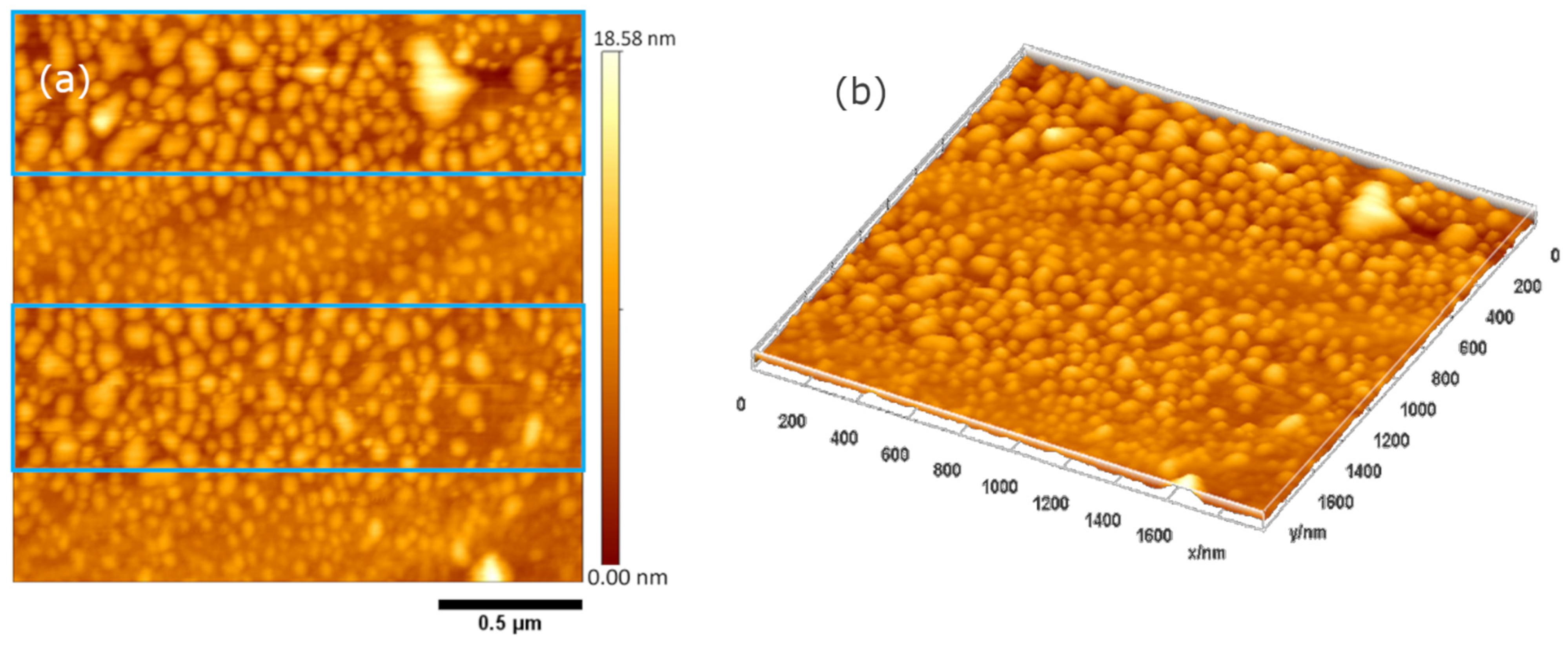
The initiation of coating growth relies on the existence of catalysts. The diamond surface after pretreatment was scanned with atomic force microscopy (AFM). The height image is shown in Figure 3a, where the bright color indicates a higher height and the dark color indicates a lower height. The brighter particles in Figure 3 are the palladium clusters for catalyzing the electroless deposition. To better visualize the particle distribution, a 3D rendered image is shown in Figure 3b. From Figure 3, it is observed that the particles sizes are not evenly distributed but vary with the substrate height. Inside the blue boxes in Figure 3a, the background is darker red, meaning the substrate surface is shallower. The clusters sizes’ distributions inside and outside the blue boxes were analyzed respectively, using ImageJ software. The average size of catalyst clusters inside the blue boxes is 58 nm, while the value outside the blue boxes is 43 nm. Therefore, we can conclude that the lower altitude surface tends to have larger catalyst clusters after the pretreatment.
The distribution of catalyst clusters gives a clue as to how the substrate morphology affects the initiation of coating deposition. For rough substrate surfaces, there are lots of upper and lower regions so that large catalyst clusters are present. The existence of these large catalyst clusters, which stick out of the average surface in the deposition solution, accelerate the mass transfer, and initiate the coating deposition at those locations.

3.1.3. Concentration of Reducing Agent

Here, we discuss the effects of the concentration of reducing agents to coating coverage rate. From Figure 2, the coating coverage rate for short plating times (5 and 10 min) first increases with the reducing agent concentration (from Ni:P = 1:1 to Ni:P = 1:2), and then decreases for the Ni:P = 1:3 samples and increases again (Ni:P = 1:4). This changing trend is mainly because the reducing agent concentration influences the coating morphology in two ways. First, with a higher concentration of the reducing agent (sodium hypophosphite), the deposition rate is faster, so the coating coverage rate increases. However, the higher concentration of reducing agents causes the plating process to be more violent, in which the produced hydrogen gas heavily agitates the solution. This agitation causes the diamond particles in the solution to move more vigorously, and chances of particle collisions increase. Besides, the turbulent flow around the particle may introduce local cavitation on the coating surface. Both particle–particle collision and fluid erosion increase the probability of the coating fracture, and thus reduce the coating coverage rate.

3.1.4. Processing Factors Affecting Coverage

The above-mentioned three factors are working together to influence the coating coverage rate on diamond particles. The diamond surfaces with more irregularities tend to have larger catalyst clusters and therefore are deposited with the coating first. During the deposition, the release of hydrogen bubbles from the coating surface agitates the solution. It causes the weakly bonded coating to detach from the diamond surface, which leads to a reduction in the coating coverage rate. The deposition process continues on the exposed diamond surface after coating is peeled off. It is likely that the bear surface of diamond would allow catalysts to say on its surface. Therefore, the coverage rate of coating on a randomly shaped diamond particle depends on the timing of both the deposition and detaching process, both of which are dynamic and influenced by the synergistic effect of the deposition time, substrate morphology, and reducing agent concentration.
In this study, Ni:P = 1:2 solution resulted in the best coverage rate for the deposition time from 5 to 30 min. Lower reducing agent concentration requires longer deposition time to reach a better coating coverage rate. When increasing the deposition time for Ni:P = 1:2 solution or increasing the reducing agent concentration, the coatings all see more fracture and deflection or curling sites. Although plating for an extremely long time can provide full coverage, it is economically less efficient because it wastes more metal and consumes more time. Therefore, while keeping all the other plating parameters the same (other chemical concentrations, plating temperature: 70 °C, pH = 9), it is recommended to use the solution with the reducing agent concentration of 0.2 mol/L and deposition between 5 and 30 min.

3.2. Coating Morphology

The electroless deposition can create coatings of various surface morphologies depending on the deposition conditions. The coating generated in the electroless deposition is smoother and more uniform in thickness compared to electroplated coatings [28]. But sometimes, the coatings exhibit nodular morphology, which consists of semi-spheres protruding from the coating surface [29,30].
Different morphological features of the coatings are desired for different applications. For machining tools used in processes that require high dimensional accuracy, such as a single-layered abrasive wheel, smooth coatings with uniform thickness on abrasive particles are desired [19,29,31]. While the nodular coating morphology is better for particle-reinforced composites because it increases the contact surface area with the matrix, thus prevents abrasive grits from pullout [32,33,34].
The morphology can be adjusted through the deposition parameters, such as the deposition time, the reducing agent concentration, pH values, and additives [34,35], but a systematic study to understand the mechanism of how these parameters affect the morphology is still lacking.
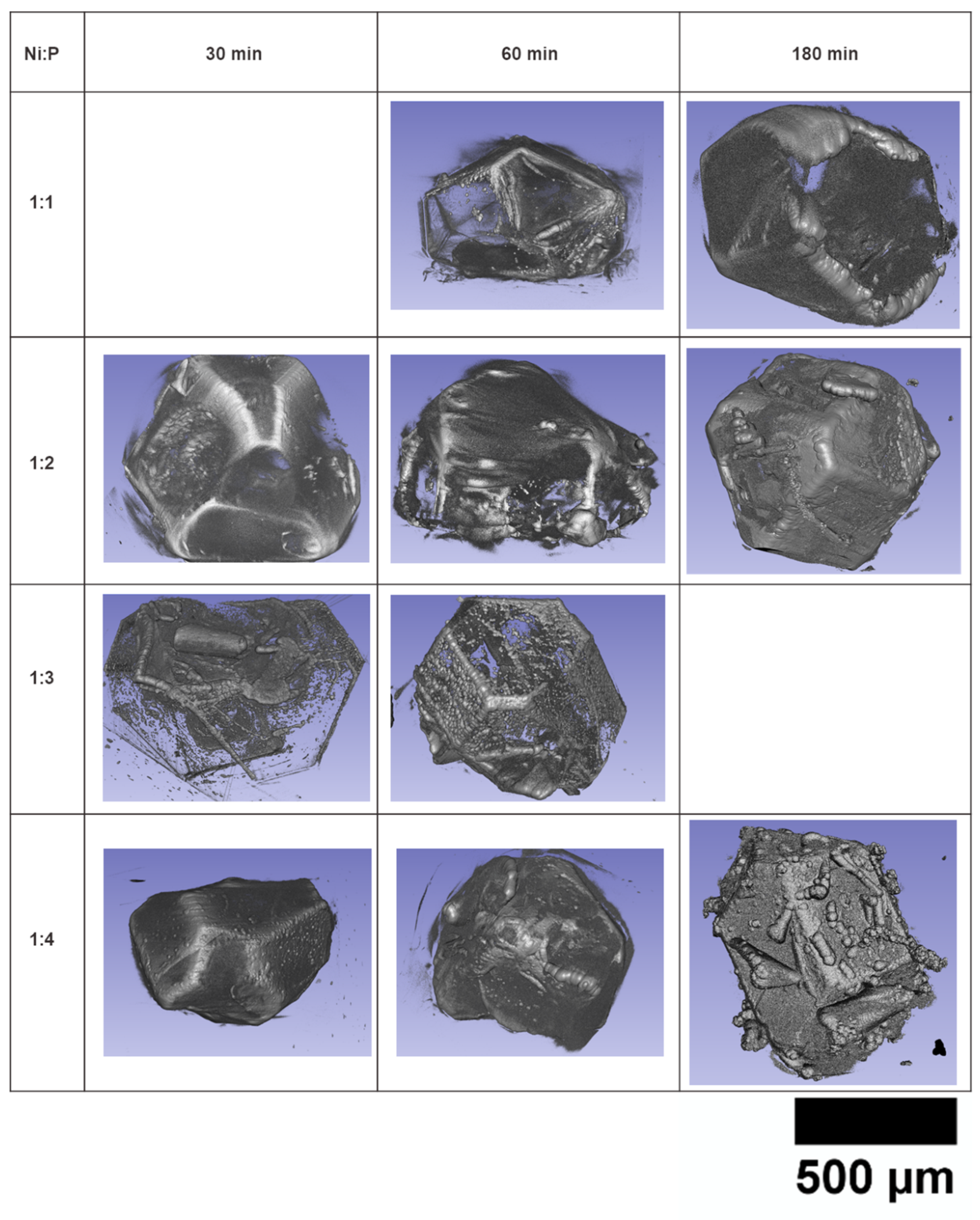
In this paper, the morphological analysis of coating is based on the optical images, SEM (Scanning Electron Microscopy) images, and 3D rendered images from the micro-CT scans, among various imaging techniques. The 3D rendered images are processed from the micro-CT scanned data. These images enable the view fields with a wide range of magnifications and from various angles. Since the 3D rendered images with thinner coating contain too much noise, only the samples with deposition time equal to or longer than 30 min are analyzed. The views from selected angles of the 3D images are shown in Figure 4.
There are three factors found to affect the morphology of a coating: deposition parameters, coating integrity, and substrate morphology.

3.2.1. Deposition Parameters

The two deposition parameters studied in this research: deposition time and the reducing agent concentration, are demonstrated to influence the coating morphology. From the optical images in Figure 2, it is found that the coatings plated for short times all exhibit a shinier surface than longer plated coatings. The glossiness of the coating in the optical images can tell whether a coating surface is smooth or rough. A smooth coating reflects light in a mirror-like direction, and hence exhibits a shiny appearance. In contrast, a rough coating looks dull because the light goes through diffuse reflection. Therefore, albeit having a low resolution, the optical images still demonstrate that longer plating time renders the rougher coating surface. For some of the samples deposited for 60 and 180 min, not only are the coatings dull, but also the nodules become big enough to see directly in these images. The detailed images of samples plated in the Ni:P = 1:3 and Ni:P = 1:4 solutions in Figure 4 show that the size of nodules increases with deposition time. It is also found that higher reducing agent concentration produces a rougher coating surface compared to that deposited in a lower concentration solution for the same deposition time.
To understand why the morphology is influenced by the deposition parameters, we need to understand the coating nucleation and growth process in an electroless deposition. When a substrate is immersed in the plating bath, the palladium clusters on the surfaces will catalyze the reduction of nickel ions at discrete nucleation sites. The nickel atoms precipitate around the nucleation sites and merge to form hemispheres for lowering surface energy. As the deposition continues, these hemispherical deposits grow bigger until they meet their neighbors and merge into a continuous film [36]. The relatively dense and uniformly distributed nucleation sites grow into the same small sizes before merging, and thus generate coating with a smooth surface, as illustrated in Figure 5a. If the nucleation sites are loosely distributed, they will grow larger before merging, so the film formed will be rough, as demonstrated in Figure 5b.
The nuclei density depends on the catalyst’s type and distribution and the concentration of reactants in the plating solution. Figure 3 shows that the palladium catalyst clusters almost cover the entire diamond surfaces after pretreatment, which means the entire diamond surface can catalyze the reduction reaction. The reactants concentration determines the Gibbs free energy change (ΔG of the reduction reaction, which is the driving force of the deposition). At the beginning of the deposition, the concentrations of reactants are high, so the driving force is high. Therefore, a large number of nucleation embryos can overcome the energy barrier induced by the increase of surface energy and form stable nuclei. This high nucleation density results in a smooth, shiny surface by the naked eye. After the first continuous coating is formed, the surface is fully covered with Ni-P alloy, which has a lower catalytic activity than palladium. After deposition for a while, the solution concentration is reduced. Both of the changes in catalyst type and reactant concentration result in a lower nucleation density and hence a rougher coating surface. This phenomenon is manifested in Ni:P = 1:4—30and 60 min samples in Figure 4, where some discrete hemispherical nodules are on top of a smooth layer of coatings.

3.2.2. Coating Integrity

The quality of the coating influences the formation of nodular morphology. From the Ni:P = 1:1—60 and 180 min, Ni:P = 1:2—60and 180 min, and Ni:P = 1:4—180 min samples in Figure 4, nodular morphology is seen on the edges of the fractured coatings. During a deposition, the coating fracture is usually accompanied by coating deflection, which causes the fractured edges to detach from the diamond surfaces. After the edge detaches, the continued coating growth from the edge is catalyzed by the Ni-P, and the fracture occurs after the first continuous film is formed when the concentration of the solution becomes lower. So low nucleation density leads to the nodular morphology formation at the fractured coating edges as well.
From the same samples in Figure 4, we can see that the coating at the fractured edge seems to be thicker. This might be due the fact that the fractured edge area was open with more supplies of reactants. This edge type of nodular morphology is not desirable since the newly grown coating is not touching the diamond surface. Hence, there is no or little adhesion force. Besides, this dangling piece of coating will be easily knocked off the substrate by collisions or fluid drag during the deposition process.
When a cracked coating peels off the substrate surface, nodular morphology tends to form on the original substrate surface. This was observed in the Ni:P = 1:3—30and 60 min samples in Figure 4, which show both continuous smooth coatings and separate nodules. As discussed in Section 3.1, the coatings formed in this solution have lots of fractures and peeling-offs. The continuous smooth coatings are formed by the coalescences of deposits around the high-density nuclei formed at an early stage of the deposition. The nodular morphology is formed after the initial coating has peeled off. After the coating failure, which exposes the underlying diamond surfaces to the plating bath, new nucleation sites with lower density will be formed. Similarly, the lower nucleation density might be due to less supply of reactants. Due to the discontinuity of these nodular deposits, this kind of morphology is not desired because it cannot provide full coverage and protection for the diamond substrate.

3.2.3. Substrate Morphology

The surface morphology of a substrate affects the nodular morphology with a different mechanism. Ideally, the nucleation only takes place on the diamond substrates. However, when impurities appear in the solution, nucleation in the solution occurs. The growth of the nuclei in the solution creates spherical deposits, and when such spheres encounter a diamond particle, they have a chance to attach to the diamond surface. If the deposition reaction occurs near the interface between the attached spheres and the coating, the attached spheres will be “welded” to the coating. The chance of these spheres to settle down is high when the encountered surface is concave. The evidence of this behavior is shown in Figure 5a within the blue boxes, where a large number of spherical particles aggregate on the rugged surface. The nodules created in this manner can be somewhere between a whole sphere and a hemisphere. This process results in the spherical nodular morphology in the Ni:P = 1:2—30 min and Ni:P = 1:4—180 min samples in Figure 4.
We can add some impurities or increase the concentration of the reactants to promote the nodular morphology formed in this mechanism. However, if the parameters are not controllable, solution decomposition may occur, which means most deposits are in powder form, and very little deposit is formed on the diamond surface.

3.2.4. Process Parameters Affecting Morphology

Four kinds of nodular morphologies are found on the electrolessly deposited coatings on diamond particles. They are on top of a uniform coating, on the edge of a fractured coating, on the surface from which a previous coating is detached, and on a rough substrate surface. The mechanisms of the nodular morphology formation are either due to a lower nucleation density on the substrate or a high nucleation rate in the solution. Understanding this, we can provide the process suggestions for the desired morphology.
The measures to ensure a smooth and uniform coating include low coating thickness, good coating integrity, and flat substrate morphology. On the other hand, if a coating with nodular morphology is required, a rough substrate and a thicker coating should be used. However, any causes to introduce coating failure should still be avoided because even though coating fracture may help form nodular morphology, it may also render partial or complete coating loss.

3.3. Deposition Kinetics

The kinetics of electroless deposition provides a guideline to choose the solution compositions and operation parameters for the desired thickness. Many factors are affecting the deposition kinetics. In this study, we discuss the influence of crystallographic orientation and reactants’ concentrations.

3.3.1. Influence of Crystallographic Orientation

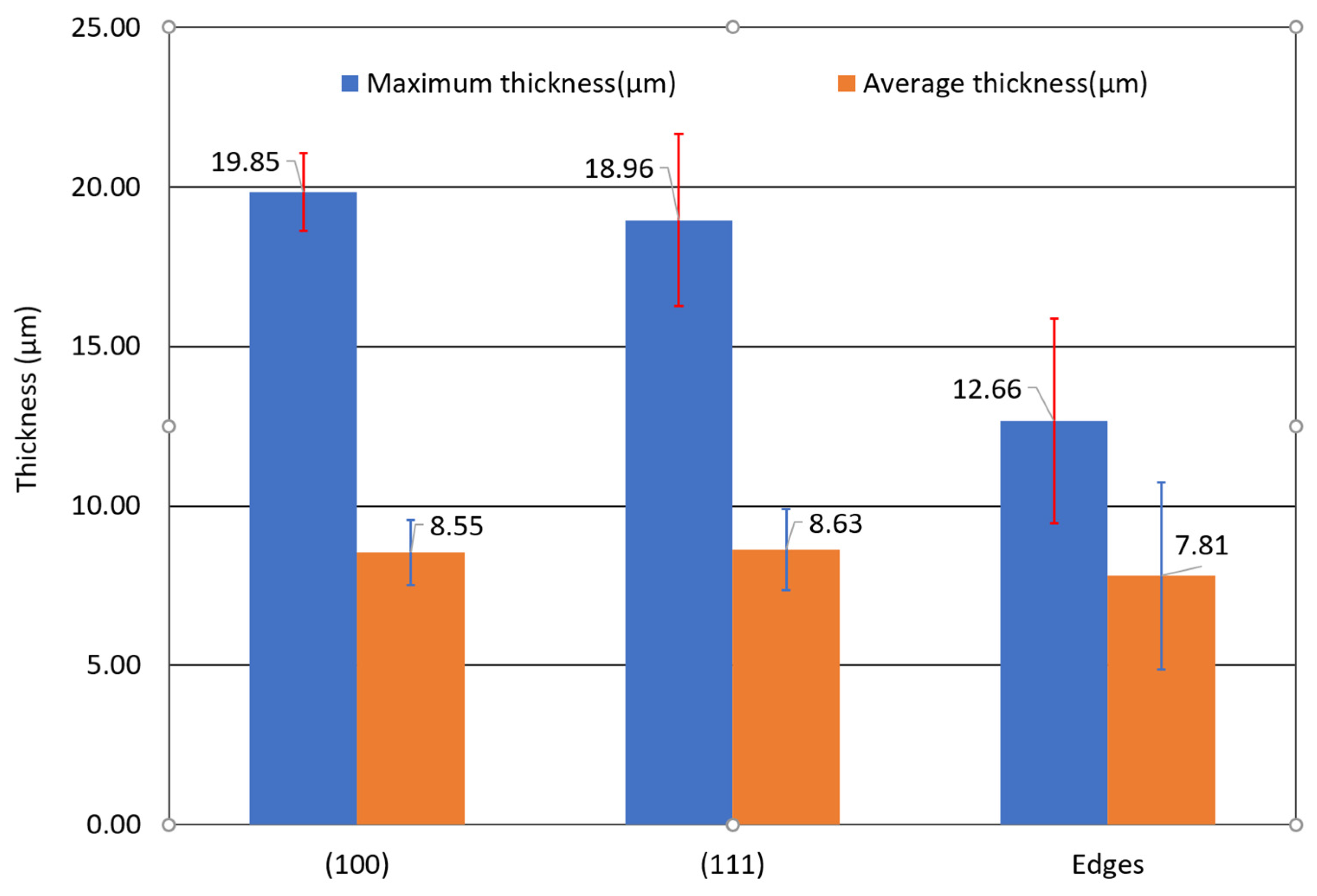
The thickness of the coatings on diamond surfaces with different crystallographic orientations was obtained from the tomographic images for the Ni:P = 1:2—10 min sample. This specific sample is investigated since it has integral coatings on all of the faces. The 14 faces on this diamond particle are numbered 1 to 14, as shown in Figure 6. They can be divided into two categories: six (100) faces and eight (111) faces, among which four (100) and eight (111) faces are provided with clear pixel information to be discussed here. The thickness distribution of each face is obtained using a python code. Only the thickness of the smooth part of each face is processed so that the noises on the rough surface are eliminated. The obtained thickness distributions are shown in Figure 7. The rectangular surfaces in the first column are (100) faces, and the hexagonal or triangular surfaces in the second and third columns are the (111) faces. The thickness of the edges was also obtained.
The orientation of a diamond crystalline plan has little effect on the coating thickness. The coating thickness is represented by the color indicated by the color bar: the blue color means a lesser thickness, and the red color indicates a greater thickness. There is non-uniformity observed on the coating thickness obtained from tomography images, as shown in Figure 7. The results show that the coatings are uniform in the coating thickness on diamond surfaces regardless of the crystallographic orientations (Figure 8).

3.3.2. Influence of Reactants’ Concentration

The coating thickness increased with deposition time. The thickness of electroless Ni-P coatings on each diamond particle was measured at flat surfaces from the tomography, and the results are plotted in Figure 9. According to the plots, the thickness increases with the plating time and the concentration of the reducing agent. In Figure 9, it is seen that the coating thickness change with time has a steeper slope initially, and then the slopes decrease.
The deposition rate of a coating decreases with time. The average deposition rate was calculated by dividing the coating thickness by the deposition time, and the results are shown in Figure 10. From this figure, the initial deposition rate is high and then decreases significantly within 20 min of deposition. After 1 hour’s deposition, the rates decrease to a very low value. The deposition rate exhibits an increasing trend with the increase of the initial reducing agent concentration.
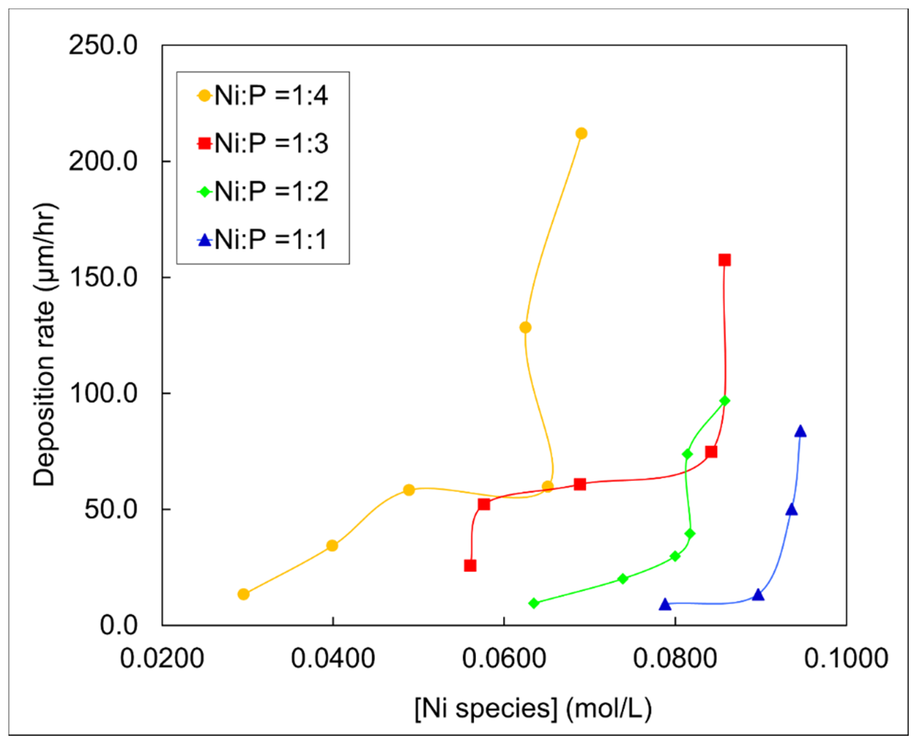
The deposition rate changes with the nickel species concentration are plotted in Figure 11. The curves are showing two separate stages. At low nickel species concentration, the deposition rates are low, and there is a linear correlation between deposition rate and nickel species concentration. When the nickel species concentration increases to a certain value, the deposition rate dramatically increases to a high value, and there is no correlation between the nickel species concentration and the deposition rate. This phenomenon is in accordance with other reports [37,38], yet there has been no explanation in their studies.

3.4. Physical Model for Coating Failure

3.4.1. Coating Failure Locations

The coatings on diamond particles are damaged preferentially at certain locations. The locations of coating fracture and peeling off are encircled with different colors in the optical images of the as-plated samples, as shown in Figure 12. Most of the coating failures are found on the corners of the diamond particles (marked with green circles). Some of the failures are located on a flat surface of the diamond particles (marked with red circles). On the other hand, for the rough substrate surface, the coatings are in good shape (marked with blue circles).

3.4.2. Origins of Residual Stresses

Residual stress in the coating due to the interfacial mismatch affects adhesion. The residual stress created during the deposition process is the main cause of the coating failure when there are no other external forces exerted on the coatings. The residual stresses in a coating arise from different origins, which include lattice misfit, defect annihilation, impurity inclusion, phase transformation, and crystallites coalescence. The possible origins are analyzed below to find out the critical ones which lead to the stress and cause the coating failure during the electroless deposition.
First, the lattice misfit is ruled out of the true origin in the electroless deposition. Since the generated coating is amorphous or polycrystalline, either there is no regular lattice parameter in the coating, or the lattice misfit is compensated by the grain boundaries. So, the stress due to the difference in atomic spacing will not be accumulated in the coating.
The defects annihilation may also introduce residual stresses in the electroless deposition process, but they will be on a much smaller scale. The defects include vacancies, dislocations, and grain boundaries, which can be annihilated by diffusion. However, the low-temperature nature of the process indicates that the annihilation of these defects occurs at a very low frequency during electroless deposition. So, the stress generated will be very small.
The possible phase transformation of the Ni-P coating is from the amorphous phase to α-Ni and Ni3P, but the temperature of transformation is 891 °C according to the Ni-P phase diagram [39]. Since the deposition occurs at a relatively low temperature, the phase transformation is not likely to take place.
It was established that the electroless deposition is accompanied by the nodular crystallite’s aggregation and growth [29,31], which is also seen in our coatings, as shown in Figure 5. In a deposition process, the initiation of the coating is from heterogeneous nucleation sites. Those sites are away from each other and grow bigger as the deposition time increases. Once the gap between the two crystallites becomes small enough, the cohesive force will attract the nearby crystallites. Because the bottoms of the crystallites are fixed on the substrate surface, the top portion of the crystallites will deform elastically and coalesce under the cohesive force. The coalescing results in a reduction of two units of solid–liquid interfacial energy and one unit of the grain boundary energy. Hence, the total surface energy of the coating is decreased [40,41]. The deformation is aiming to close the gap between the crystallites and reduce the total surface energy, so there will be stretching tensile stress generated in the coating.
Based on the analysis above, the residual stress generated by the crystallites’ coalescence in the electroless deposition is the dominating stress causing coating fracture.

3.4.3. Estimation of the Residual Stress

From the theory of residual stress originated from coalesces of crystallites, the magnitude of the residual stress can be estimated. The tensile stress generated in the coalescence is derived by Freund and Chase with a simple model [41]. Equation (1) is used to calculate the average stress between two contacting spherical crystallites:
σ a v e = 4 ( γ s l 1 2 γ g b ) R
where, γ s l is the surface energy at the solid–liquid interface and γ g b is the grain boundary energy.
Since the electroless deposition occurs in the solid–liquid interface, the surface energy in the equation is the interfacial energy between the plating solution and the deposited Ni-P alloy. The electroless Ni-P coatings have very different compositions and microstructure. Thus, the interfacial energy and grain boundary energies lack data. Therefore, the interfacial energy of pure nickel and water and the grain boundary of pure nickel from the literature are used to estimate the residual stress. The surface energy, γ s v , and grain boundary energy, γ g b , of nickel are 1.78 and 0.57 J/m2, respectively [42]. The solid–liquid interfacial energy is estimated using Equation (2), with the surface energy of water at 70 °C to be 0.0644 J/m2:
γ s l = γ s v γ l v c o s θ
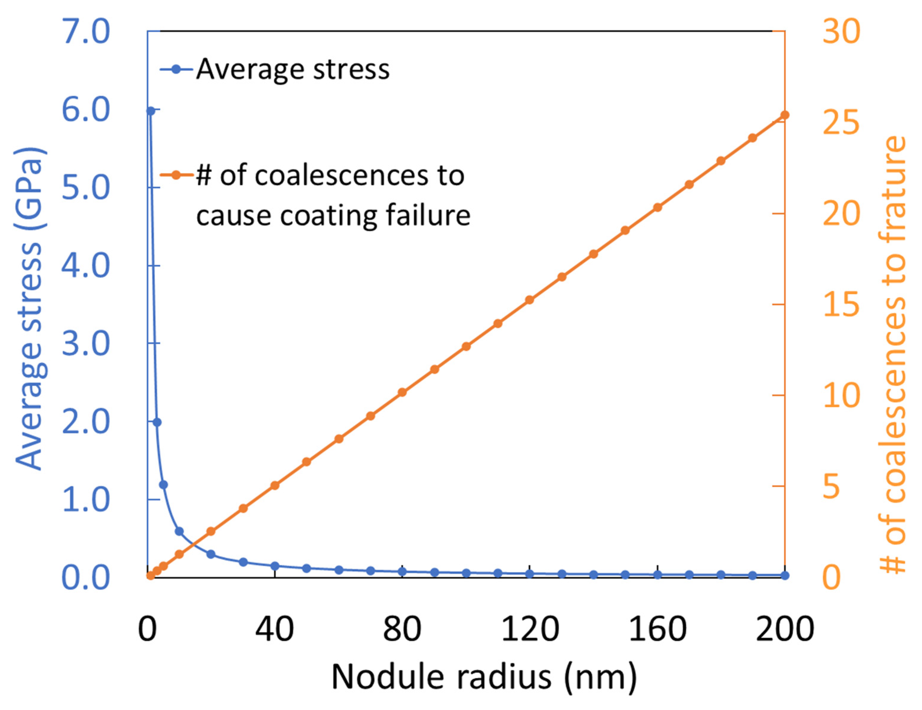
The contact angle of nickel with water, θ, is measured to be around 90° for as-plated coating [43]. By plugging in all the data, the average stress in the coalesced crystallite is calculated for different nodular radii. The results are plotted in Figure 13 with blue dots and the blue curve. Equation (1) discloses that the average stress is inversely proportional to the radius of the crystallite. The estimated stress values show that for two crystallites of 1 nm radius, their coalescence can generate tensile stress as high as 6 GPa.
A simple criterion to determine whether the coating will fracture is by comparing the residual stress with the tensile strength of the coating material. Many researchers have tested the tensile strength of electroless-deposited Ni-P coatings with different compositions and after different heat treatment, in which the maximum tensile strength of as-plated Ni-P is 760 MPa [44,45,46]. When the crystallite radius is 7.8 nm, the stress is equal to the tensile strength of the coating.
However, the coating fracture is not likely to occur with only two nodules’ coalescence because when the crystallites are too small, they are too far away from each other to coalesce. It is more likely when the crystallite grows bigger and more coalescences occur successively. When the accumulated stress is bigger than the tensile strength, the coating breaks. Assuming the stress created by crystallite coalescence is cumulative, the number of successive coalescences that lead to the coating failure can be calculated. The calculated results are plotted in Figure 13. The plot shows that when crystallites radius is 80 nm, it takes 10 successive coalescences for the generated residual tensile stress to tear the coating apart.

3.4.4. Coating Failure Mechanisms

From the previous discussion, it is concluded that the coating in the electroless deposition process fails due to the accumulated residual tensile stress generated by the coalescence of crystallites that forms the coating. Based on this conclusion, the variation in resistance to coating failure against substrate morphological features can be explained. From the sketches in Figure 14, it is shown that the directions of stresses generated by crystallite coalescence change with the substrate morphologies. On a flat and smooth surface, as seen in Figure 14a, the tensile stresses generated are parallel to the substrate surface when the crystallites coalesce. As more and more crystallites coalesce, the stress accumulates until the weakest point in the coating fractures. For the corner of a diamond substrate, presented in Figure 14b, the tensile stresses are also parallel to the substrate and can accumulate when more crystallites merge, but the sharp corner acts as a stress concentrator, so it is easy to fracture. For a surface with some waviness, as shown in Figure 14c, the direction of tensile stress changes with the substrate waviness. In this case, the tensile stress may not accumulate to a big enough value if the distance between the peak and valley is too short, which prevents the coatings from fracture failures. Suitable substrate surface texture can be designed based on this mechanism to avoid coating failure. The abrasive used in the silicon wafer cutting process can utilize this texturing process. The reduced coating failure can reduce the tool wear and increase productivity.

4. Conclusions

This research investigated the electroless plated Ni-P coatings on diamond grits through morphological characterizations in order to understand the coating deposition process and its failure mechanisms. The major findings have been summarized.
The morphological study of the electroless Ni-P on diamond particles was conducted using X-ray tomography along with several other microscopic methods. The following conclusions were drawn:
  • The coating coverage rate on diamond particles is affected by the synergistic action of the deposition time, substrate morphology, and reducing agent concentration.
  • The two major morphological features of the coating: nodular and smooth, are influenced by the deposition parameters, coating integrity, and substrate morphology.
  • The deposition rate was found to be dependent on the concentrations of the reactants.
  • The morphological features of the substrate, which affect the coating failures tendencies, were recognized. Flat smooth surface and corner areas promote the coating failure, while rough surfaces retain the coating.
  • The coating’s fracture is caused by the residual stress developed during the deposition process.
This study provided two novel methods to characterize the electroless Ni-P coatings on abrasive diamond grits. Firstly, a self-designed electrode was used, which enables the collecting of electrochemical signals in corrosion tests. Secondly, by applying X-ray tomography techniques that enable the 3D views in high resolution, detailed information of the coating on the diamond particles was obtained. These methods can be applied to other metal coatings/powder substrate systems.

Author Contributions

Conceptualization, H.L.; Data curation, L.M., Y.C., P.R. and D.P.; Formal analysis, L.M. and H.L.; Methodology, D.P. and H.L.; Supervision, H.L.; Writing—original draft, L.M.; Writing—review & editing, A.F. and H.L. All authors have read and agreed to the published version of the manuscript.

Funding

This research received no external funding.

Acknowledgments

Peter Renner was sponsored by the NSF Grad Fellowship. This research used resources of the Advanced Light Source, a U.S. DOE Office of Science User Facility under contract No. DE-AC02-05CH11231.

Conflicts of Interest

The authors declare no conflict of interest.

References

  1. Brenner, A.R.G. Nickel Plating by Chemical Reduction. U.S. Patent US2532283A, 5 December 1950. [Google Scholar]
  2. Shacham-Diamand, Y.Y. Electroless copper deposition using glyoxylic acid as reducing agent for ultralarge scale integration metallization. Electrochem. Solid State Lett. 2000, 3, 279–282. [Google Scholar] [CrossRef]
  3. Yoshino, M.; Nonaka, Y.; Sasano, J.; Matsuda, I.; Shacham-Diamand, Y.; Osaka, T. All-wet fabrication process for ULSI interconnect technologies. Electrochim. Acta 2005, 51, 916–920. [Google Scholar] [CrossRef]
  4. Vossen, J.L.; Schnable, G.L.; Kern, W. Processes for multilevel metallization. J. Vac. Sci. Technol. 1974, 11, 60–70. [Google Scholar] [CrossRef]
  5. Sricharoenchaikit, P.; Calabrese, G.S.; Gulla, M. Controlled Electroless Plating. US Patent US5203911A, 20 April 1993. [Google Scholar]
  6. Aal, A.A.; Shaaban, A.; Hamid, Z.A. Nanocrystalline soft ferromagnetic Ni–Co–P thin film on Al alloy by low temperature electroless deposition. Appl. Surf. Sci. 2008, 254, 1966–1971. [Google Scholar] [CrossRef]
  7. Balaraju, J.N.; Selvi, V.E.; Grips, V.K.W.; Rajam, K.S. Electrochemical studies on electroless ternary and quaternary Ni–P based alloys. Electrochim. Acta 2006, 52, 1064–1074. [Google Scholar] [CrossRef]
  8. Georgieva, J.; Armyanov, S. Electroless deposition and some properties of Ni–Cu–P and Ni–Sn–P coatings. J. Solid State Electr. 2007, 11, 869–876. [Google Scholar] [CrossRef]
  9. Shashikala, A.R.; Mayanna, S.M.; Sharma, A.K. Studies and characterisation of electroless Ni–Cr–P alloy coating. Trans. IMF 2013, 85, 320–324. [Google Scholar] [CrossRef]
  10. Fukumuro, N.; Nishiyama, J.; Shigeta, K.; Takagami, H.; Yae, S.; Matsuda, H. Confirmation of hydroxide in electroless cobalt alloy films by GDOES. Trans. IMF 2013, 85, 111–112. [Google Scholar] [CrossRef]
  11. Nwosu, N.O.; Davidson, A.M.; Hindle, C.S. Effect of Sodium Dodecyl Sulphate on the Composition of Electroless Nickel—Yttria Stabilized Zirconia Coatings. Adv. Chem. Eng. Sci. 2011, 1, 118–124. [Google Scholar] [CrossRef] [Green Version]
  12. Fayyad, E.; Abdullah, A.; Hassan, M.; Mohamed, A.; Wang, C.; Jarjoura, G.; Farhat, Z. Synthesis, Characterization, and Application of Novel Ni-P-Carbon Nitride Nanocomposites. Coatings 2018, 8, 37. [Google Scholar] [CrossRef] [Green Version]
  13. Winowlin Jappes, J.T.; Ramamoorthy, B.; Kesavan Nair, P. Novel approaches on the study of wear performance of electroless Ni–P/diamond composite deposites. J. Mater. Process. Tech. 2009, 209, 1004–1010. [Google Scholar] [CrossRef]
  14. Alexis, J.; Gaussens, C.; Etcheverry, B.; Bonino, J.-P. Development of nickel–phosphorus coatings containing micro particles of talc phyllosilicates. Mater. Chem. Phys. 2013, 137, 723–733. [Google Scholar] [CrossRef] [Green Version]
  15. Balaraju, J.N.; Kalavati; Rajam, K.S. Influence of particle size on the microstructure, hardness and corrosion resistance of electroless Ni–P–Al2O3 composite coatings. Surf. Coat. Technol. 2006, 200, 3933–3941. [Google Scholar] [CrossRef]
  16. Mafi, I.R.; Dehghanian, C. Comparison of the coating properties and corrosion rates in electroless Ni–P/PTFE composites prepared by different types of surfactants. Appl. Surf. Sci. 2011, 257, 8653–8658. [Google Scholar] [CrossRef]
  17. Huang, Y.S.; Zeng, X.T.; Annergren, I.; Liu, F.M. Development of electroless NiP–PTFE–SiC composite coating. Surf. Coat. Technol. 2003, 167, 207–211. [Google Scholar] [CrossRef]
  18. Ankita, S.; Singh, A.K. Corrosion and wear resistance study of Ni-P and Ni-P-PTFE nanocomposite coatings. Cent. Eur. J. Eng. 2011, 1, 234–243. [Google Scholar] [CrossRef]
  19. Okumiya, M.; Tsunekawa, Y.; Saida, T.; Ichino, R. Creation of high strength bonded abrasive wheel with ultrasonic aided composite plating. Surf. Coat. Technol. 2003, 169–170, 112–115. [Google Scholar] [CrossRef]
  20. Dong, Y.-H.; He, X.-B.; Ud-Din, R.; Guo, C.-Y.; Xu, L.; Huang, Y.-T.; Qu, X.-H. Fabrication and thermal stability of Ni-P coated diamond powder using electroless plating. Int. J. Miner. Metall. Mater. 2011, 18, 479. [Google Scholar] [CrossRef]
  21. Petrova, M.; Noncheva, Z.; Dobreva, E. Electroless deposition of diamond powder dispersed nickel—Phosphorus coatings on steel substrate. Trans. IMF 2013, 89, 89–94. [Google Scholar] [CrossRef]
  22. Ma, L.; He, X.; Fang, A.; Liang, H. Electrochemical Characterization of a Nickel-Phosphorus Coating on Diamond Grits. Mater. Perform. Charact. 2018, 7, 266–280. [Google Scholar] [CrossRef]
  23. Loto, C.A. Electroless Nickel Plating—A Review. Silicon 2016, 8, 177–186. [Google Scholar] [CrossRef]
  24. Lambert, R.M.; Pacchioni, G.; North Atlantic Treaty Organization, Scientific Affairs Division. Chemisorption and Reactivity on Supported Clusters and Thin Films: Towards an Understanding of Microscopic Processes in Catalysis; Kluwer Academic Publishers: Dordrecht, The Netherlands; Boston, MA, USA, 1997. [Google Scholar]
  25. Pietsch, P.; Wood, V. X-ray tomography for lithium ion battery research: A practical guide. Annu. Rev. Mater. Res. 2017, 47, 451–479. [Google Scholar] [CrossRef]
  26. Beamline 8.3.2 Manual. Available online: http://microct.lbl.gov/manual (accessed on 13 February 2021).
  27. de Oliveira, M.C.L.; Correa, O.V.; da Silva, R.M.P.; de Lima, N.B.; de Oliveira, J.T.D.; de Oliveira, L.A.; Antunes, R.A. Structural, Adhesion and Electrochemical Characterization of Electroless Plated Ni-P-Carbon Black Composite Films on API 5L X80 Steel. J. Mater. Eng. Perform. 2019, 28, 4751–4761. [Google Scholar] [CrossRef]
  28. Parkinson, R. Properties and Applications of Electroless Nickel; Technical Series No. 10081; Nickel Development Institute: Toronto, ON, Canada, 1997; pp. 5–6. Available online: https://nickelinstitute.org/media/1769/propertiesandapplicationsofelectrolessnickel_10081_.pdf (accessed on 13 February 2021).
  29. Uchiyama, H.; Endo, T.; Sone, M. Direct Observation of Nodule Growth on Electroless Ni-P Deposition in Supercritical CO2 Emulsion. J. Electrochem. Soc. 2012, 159, D114–D118. [Google Scholar] [CrossRef]
  30. Hadipour, A.; Monirvaghefi, S.M.; Bahrololoom, M.E. Electroless deposition of graded Ni-P coatings. Surf. Eng. 2015, 31, 399–405. [Google Scholar] [CrossRef]
  31. Zhong, L.L.; Liu, C.C.; Mawla, S.A.; John, J.D.S.; Petrehn, J.L. Nodule-Free Electroless Nip Plating. US Patent US6685990B1, 3 February 2004. [Google Scholar]
  32. Son, K.S.; Lee, J.H.; Choi, Y.J.; Jung, U.C.; Chung, W.S. Effect of Intermediate Layer Coated Diamond Particles on Performance of Diamond Tool. J. Korean Inst. Surf. Eng. 2013, 46, 216–222. [Google Scholar] [CrossRef] [Green Version]
  33. Webster, J.; Tricard, M. Innovations in Abrasive Products for Precision Grinding. CIRP Ann. Manuf. Technol. 2004, 53, 597–617. [Google Scholar] [CrossRef]
  34. Xi, X.; Miao, H.; Zhang, R.; Cheng, J. Effect of phosphorus content on the properties of Ni-P coated diamond. Surf. Coat. Technol. 2016, 297, 27–33. [Google Scholar] [CrossRef]
  35. Ahn, J.G.; Kim, D.J.; Lee, J.R.; Chung, H.S.; Kim, C.O.; Hai, H.T. Improving the adhesion of electroless-nickel coating layer on diamond powder. Surf. Coat. Technol. 2006, 201, 3793–3796. [Google Scholar] [CrossRef]
  36. Marton, J.; Schlesinger, M. The Nucleation, Growth, and Structure of Thin Ni-P Films. J. Electrochem. Soc. 1968, 115, 16–21. [Google Scholar] [CrossRef]
  37. Baldwin, C.; Such, T.E. The Plating Rates and Physical Properties of Electroless Nickel/Phosphorus Alloy Deposits. Trans. IMF 1968, 46, 73–80. [Google Scholar] [CrossRef]
  38. Mallory, G.O.; Hajdu, J.B. Electroless Plating: Fundamentals and Applications; ASCE: Reston, VA, USA, 1990. [Google Scholar]
  39. Schmetterer, C.; Vizdal, J.; Ipser, H. A new investigation of the system Ni–P. Intermetallics 2009, 17, 826–834. [Google Scholar] [CrossRef]
  40. Vlassak, J. Thin Film Mechanics. 2004. Available online: https://www.mrsec.harvard.edu/education/ap298r2004/Vlassak%20AP298presentation.pdf (accessed on 13 February 2021).
  41. Freund, L.; Chason, E. Model for stress generated upon contact of neighboring islands on the surface of a substrate. J. Appl. Phys. 2001, 89, 4866–4873. [Google Scholar] [CrossRef]
  42. Clark, E.; Yeske, R.; Birnbaum, H. The effect of hydrogen on the surface energy of nickel. Metall. Trans. A 1980, 11, 1903–1908. [Google Scholar] [CrossRef]
  43. Karthikeyan, S.; Vijayaraghavan, L. Investigation of the surface properties of heat treated electroless Ni–P coating. Trans. IMF 2016, 94, 265–273. [Google Scholar] [CrossRef]
  44. Krishnan, K.H.; John, S.; Srinivasan, K.N.; Praveen, J.; Ganesan, M.; Kavimani, P.M. An overall aspect of electroless Ni-P depositions—A review article. Metall. Mater. Trans. A 2006, 37, 1917–1926. [Google Scholar] [CrossRef]
  45. Taheri, R. Evaluation of Electroless Nickel-Phosphorus (EN) Coatings. Ph.D. Thesis, University of Saskatchewan, Saskatoon, SK, Canada, 2002. [Google Scholar]
  46. Panagopoulos, C.; Papachristos, V.; Sigalas, C. Tensile behaviour of as deposited and heat-treated electroless Ni-P deposits. J. Mater. Sci. 1999, 34, 2587–2600. [Google Scholar] [CrossRef]
Figure 1. Pretreatment process of diamond abrasives for electroless plating.
Lubricants 09 00020 g001
Figure 2. Optical images of coatings on diamond particles.
Lubricants 09 00020 g002
Figure 3. Atomic force microscopy (AFM) (a) height image and (b) three-dimensional (3D) image of palladium clusters on the diamond surface.
Lubricants 09 00020 g003
Figure 4. Volume rendered images of coated diamond particles showing nodules on the surface.
Lubricants 09 00020 g004
Figure 5. Sketches illustrate the formation process of coating with (a) uniformly and densely distributed nucleation sites, (b) uniformly but loosely distributed nucleation sites.
Lubricants 09 00020 g005
Figure 6. Labels of different faces and edges of the Ni:P = 1:2—10 min diamond grit.
Lubricants 09 00020 g006
Figure 7. Coating thickness distribution on different diamond faces.
Lubricants 09 00020 g007
Figure 8. Coating thickness on different faces and edges of the Ni:P = 1:2—10 min diamond grit.
Lubricants 09 00020 g008
Figure 9. Coating thickness with different deposition time and reducing agent concentrations. The position of time is shifted a little to show the error bar.
Lubricants 09 00020 g009
Figure 10. Deposition rate change with different deposition time and reducing agent concentrations.
Lubricants 09 00020 g010
Figure 11. Relationship of deposition rate with nickel species concentration.
Lubricants 09 00020 g011
Figure 12. Optical images showing the coating failure locations: green color indicates corners, red indicates flat surface, and blue indicates rough surfaces.
Lubricants 09 00020 g012
Figure 13. Average stress between two coalesced hemispheric crystallites and the number of coalescences to cause coating failure.
Lubricants 09 00020 g013
Figure 14. Ni-P crystallites’ coalescence on different morphologies of the substrate. (a) on flate surface; (b) On the edge; (c) on the wavy surface.
Lubricants 09 00020 g014
Table 1. Pretreatment details.
TreatmentChemicalsConcentrationImmersion Time (min)
SensitizationSnCl2∙2H2O20 g/L2
HCl40 mL/L
ActivationPdCl20.5 g/L1
HCl10 mL/L
Table 2. The electroless plating bath components and concentrations.
ChemicalsConcentration (mol/L)
Nickel Sulfate hexahydrate, NiSO4∙6H2O0.1
Sodium hypophosphite monohydrate, NaH2PO2∙H2O0.1, 0.2, 0.3, 0.4
Trisodium citrate dihydrate, C6H5Na3O7∙2H2O0.1
Ammonium sulfate, (NH4)2SO40.1
Publisher’s Note: MDPI stays neutral with regard to jurisdictional claims in published maps and institutional affiliations.