Abstract
In the present study, a computational investigation into acoustic and tribological performances in journal bearings is presented. A heterogeneous pattern, in which a rough surface is engineered in certain regions and is absent in others, is employed to the bearing surface. The roughness is assumed to follow the sand-grain roughness model, while the bearing noise is solved based on broadband noise source theory. Three types of heterogeneous rough/smooth journal bearings exhibiting different placement and number of the rough zone are evaluated at different combinations of eccentricity ratio using the CFD method. Numerical results show that the heterogeneous rough/smooth bearings can supply lower noise and larger load-carrying capacity in comparison with conventional bearings. Moreover, the effect on the friction force is also discussed.
1. Introduction
Journal bearing is one of the most critical friction pairs in machine elements, in which the applied force is fully supported by the pressure of the lubricating film. The main function of the bearing is to keep the shaft always rotating about its axis, smoothing the rotary motion, reducing friction between the two surfaces, and dampening vibrations due to the rotating motion of the shaft and motor [1]. Within recent decades, a large quantity of research focusing on surface modification by texturing has been and continues to be performed. This is mainly because surface texturing has become a feasible way to improve journal bearing performance. Tala-Ighil, et al. [2] presented a detailed study relating to the effect of promoting a surface texture in the form of a cylindrical dimple by varying the location of the texture arrangement. The results of their study indicated that the application of texture on the entire bearing surface produces a detrimental effect, while on the other hand, the application of partial surface texture can improve the performance of journal bearings. Brizmer and Kligerman [3] found a potential benefit of micro-texture with laser surface texturing (LST) on the inner surface of bearings on the load-carrying capacity of journal bearings. Their finding was also confirmed by Ji et al. [4]. Later, Meng and his group [5,6,7] studied more deeply the effect of compound groove texture in various forms on tribological and acoustic performance through the computational fluid dynamics (CFD) method. Their main results stated that the optimal dimple compound can reduce noise levels and increase load-carrying capacity and frictional forces. This result was also experimentally verified by the same author [8]. Wang et al. [9] revealed that the provision of a texture in the form of a convex–concave spherical texture configuration on the bearing surface was able to significantly reduce the friction coefficient. An interesting finding was reported by Manser et al. [10] who found that by combining the effects of micro-texturing and micro-polar non-Newtonian lubricant, an enhancement load support but low friction of journal bearing was achieved. In recent lubrication, Saleh et al. [11] revealed that to get a high load-support, a convex texture with a perpendicular direction of curvature was recommended.
Furthermore, considerably more investigations into bearing performances related to surface roughness are also available. Based on the Reynolds equation, Javorova [12] demonstrated the significance of the surface roughness inclusion for the bearing performance analysis. Using Cristensen’s stochastic roughness theory, Hsu et al. [13] explored the effect of two types of surface roughness directions, namely longitudinal and transversal, under a magnetic field, on the operational performance of bearings. They showed that by promoting longitudinal roughness, the load-carrying capacity can be enhanced. On the other hand, the opposite effect was observed when transverse roughness is employed. For the bearing with slip/no-slip pattern, Kalavathi et al. [14] derived the generalized Reynolds equation by considering roughness nature by employing Christensen’s stochastic theory. They identified that the influence of roughness plays a notable role on the load-carrying capacity. It was confirmed that the load-carrying capacity increases with surface roughness. Later, the effects of surface roughness on the transient behavior of hydrodynamic journal bearings during startup were explored by Cui et al. [15]. They found that the longitudinal surface configuration has a quite significant effect on reducing the hydrodynamic force. Al-Samieh [16] explored the effect of surface roughness in sinusoidal waviness terms for Newtonian and non-Newtonian lubricants. It was observed that as the amplitude of the waviness increases, more fluctuations of pressure distribution occur. Later, Tauviqirrahman et al. [17] revealed that hydrodynamic pressure and load-carrying capacity decrease with surface roughness. In their case, it was assumed that the roughness was applied to the whole bushing surface. Recently, Gu et al. [18] reported that the surface roughness should be taken into account in the optimization of the surface texture. In general, as well as the surface texture, the surface roughness has a significant role in altering the tribological performance of the journal bearing.
In the present work, an investigation into the enhancement of the performance of journal bearings via an engineered rough surface, with emphasis on improving tribological indices and enhancing the acoustical performance (i.e., low noise), is studied utilizing the computational fluid dynamics (CFD) approach. By designing an engineered heterogeneous bearing surface, on which the roughness is applied to a certain area and is absent in others, the lubrication performance can be improved. The so-called heterogeneous rough/smooth pattern introduced here is inspired by the construction of heterogeneous slip/no-slip surface. As reported by numerous researchers, for example [14,19,20,21,22,23,24], the heterogeneous slip/no-slip configuration was proven to increase the load-carrying capacity and reduce the friction force significantly. It is believed that a configuration of rough/smooth regions will lead to enhanced journal bearing properties. In this analysis, to capture the cavitation phenomena in a more proper way that may occur in the bearing, the multi-phase cavitation approach is adopted as discussed by many workers [25,26,27,28]. Moreover, based on the survey literature, remarkable progress in the research of roughened journal bearings is mainly concerned with tribological characteristics. Few studies have been devoted to investigating the effect of surface roughness on bearing noise. Therefore, in this study, in addition to the tribological performance, the acoustic characteristic of bearing is of particular interest.
2. Theory
2.1. Governing Equations
In the present work, the flow behavior induced by the surface motion is solved by calculating the Navier–Stokes instead of the Reynolds theory for incompressible flow. In this study, the Reynolds-averaged Navier–Stokes (RANS) equation coupled with the mass conservation equation is used. To simplify the computational processing, the isothermal lubricant conditions are assumed.
The RANS equation (momentum equation) is:
The mass conservation equation is:
where is to the lubricant density; ui(uj) is the average velocity of the lubricant along the coordinates xi(xj), that is the coordinate X, Y, or Z; p is the hydrodynamic pressure; µ is the viscosity; u′i and u′j are the fluctuation velocities; is the Reynolds stress. In the present study, the standard turbulent kinetic energy k and turbulent dissipation rate εd models [29] are employed to solve the Reynolds stress.
Once the hydrodynamic pressure is calculated through Equations (1) and (2), in terms of the tribological performances, the load-carrying capacity of the bearing can be calculated by integrating the hydrodynamic pressure acting on the bearing surface, while the friction force exerted by the lubricant on the surface is obtained by integrating the shear stress over the surface area.
In the acoustic analysis studied here, the bearing noise is of particular interest. The noise tends to exist during the bearing operation due to the turbulence in the lubricant. In this work, a computational approach to solving the noise produced in the lubricant utilizes the broadband noise source model [29]. Here, the acoustic power level PA is expressed as follows [29]:
where ui and l are turbulence velocity and length scales, respectively and is the speed of the sound which is set to 1480 m/s. In Equation (3), a is a model constant. Furthermore, Equation (3) can be reduced in terms of k and εd as follows:
Here, the rescaled constant is set to 0.1 [29].
2.2. Cavitation Modeling
In this work, the mixture model of cavitation is employed as provided by CFD software. The mixture model represents vapor–liquid two-phase flow by considering that the liquid phase becomes vapor phase when the lubricant film pressure falls below the saturation pressure. Based on this approach, the growth of gas bubbles which often accompanies the cavitation process is also calculated. In this study, the multi-phase cavitation model of Zwart–Gelber–Belamri is used [29,30]. In cavitation, the liquid–vapor mass transfer (evaporation and condensation) is governed by the vapor transport equation:
where αv represents vapor volume fraction and ρv refers to vapor density. Rg and Rc account for the mass transfer between the liquid and vapor phases in cavitation. For the Zwart–Gelber–Belamri model, assuming that all the bubbles have the same size in a system, the final form of the cavitation is as follows [29,30]:
where Fevap = evaporation coefficient = 50, Fcond = condensation coefficient = 0.01, RB = bubble radius = 10−6 m, αnuc = nucleation site volume fraction = 5 × 10⁻⁴, ρ = liquid density and psat = saturation pressure.
2.3. Roughness Modeling
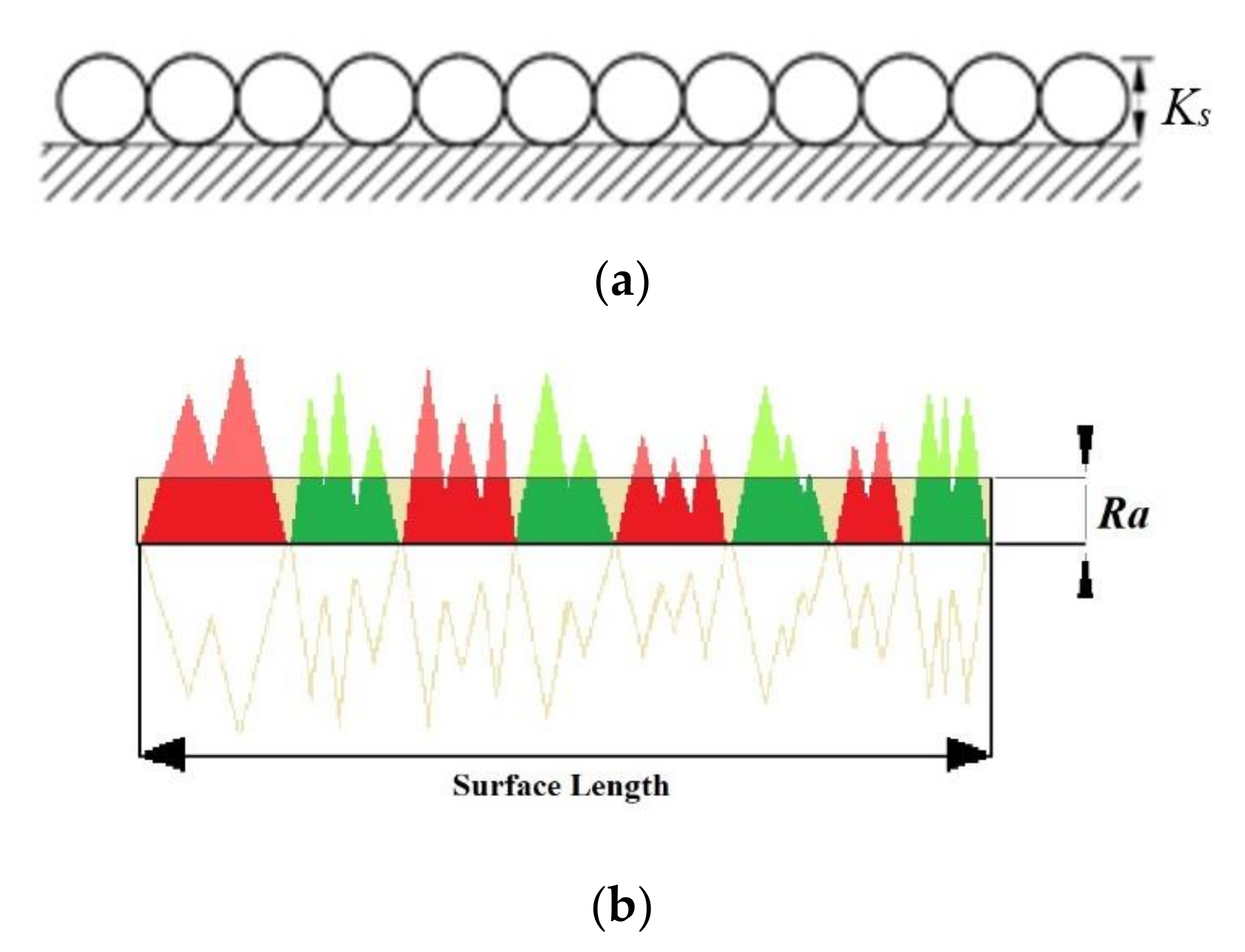
In the present study, the sand-grain model as shown in Figure 1a is adopted to characterize the roughness profile of the rough surface of the heterogeneous rough/smooth bearing. Here, a close-packed monolayer of spheres with diameter Ks is used to cover the surface uniformly. For modeling the surface roughness, the modified law-of-the-wall for mean velocity is employed. This equation can be expressed as follows [29]:
where and . For sand-grain roughness, is affected by the physical roughness height Ks, while the height is assumed constant per surface [29].

Figure 1.
(a) Uniform sand-grain roughness model; (b) Roughness profile.
It should be noted that the roughness height Ks is the equivalent sand-grain roughness height and is not equal to the geometric roughness height of the surface. Therefore, it is necessary to use the conversion factor to convert the geometric roughness height of the surface into an equivalent sand-grain roughness. In this work, the Ra as shown in Figure 1b, is chosen as a parameter to represent the roughness height Ks (Figure 1a). The Ra represents the arithmetic average of the roughness profile, and in reality it is measured by the profilometer.
For all computations here, the Ra value will be an input to specify the roughness level of the heterogeneous rough/smooth bearing. According to the experiment performed by Adams et al. [31], the correlation between Ks and Ra can be defined as follows:
In FLUENT, to model the roughness effect, two roughness parameters must be specified, that is, the roughness constant Cs and the roughness height Ks. Here, because the k-εd turbulence model is used and the uniform sand-grain is assumed, the default roughness constant (Cs = 0.5) is employed as suggested by ANSYS FLUENT [29].
3. Simulation Method
3.1. Model
The basic geometry of the journal bearing used here adopts the geometry as presented by Meng, et al. [6]. In this study, the concept of the heterogeneous rough/smooth bearing is introduced in which the rough condition is applied on certain areas while the others are smooth. From a numerical perspective, the heterogeneous roughness distribution is made by applying the surface boundary condition on the chosen area by inputting the sand-grain roughness value Ks to model the roughness. Here, the film thickness of the lubricant will follow the surface profile as the input in the CFD program.
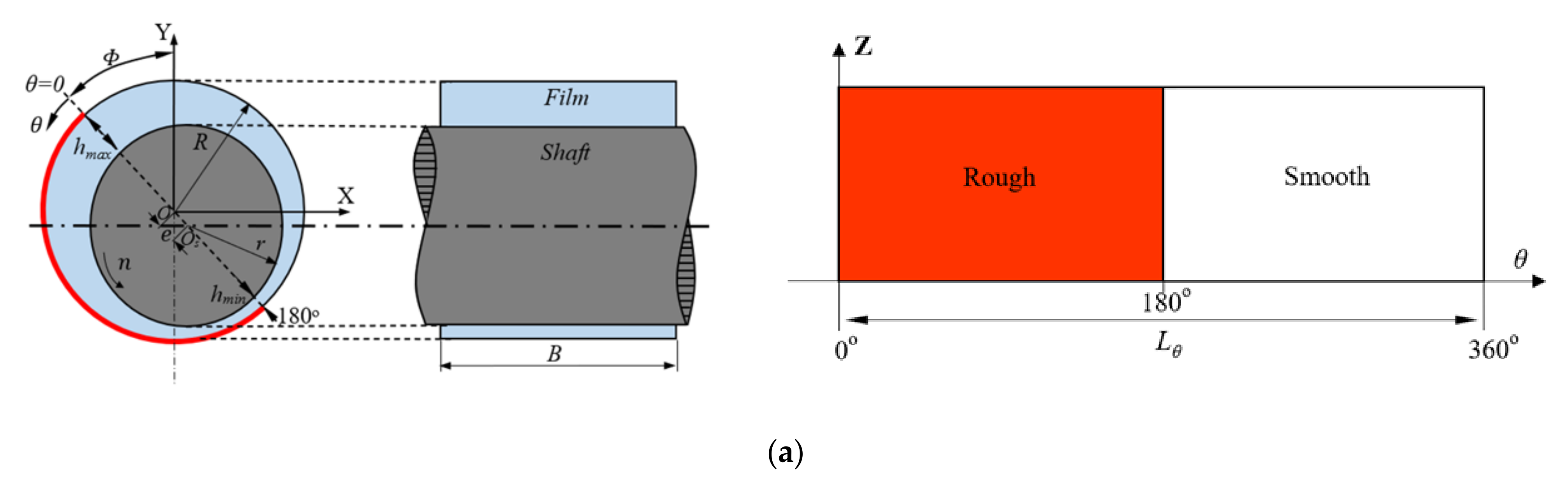
Three patterns of the heterogeneous rough/smooth journal bearing with various rough-smooth locations, namely 1 L, 2 L, and 3 L patterns, as shown in Figure 2 are studied and then compared with conventional (smooth) journal bearing (denoted as S pattern in this case). The journal bearing geometry and the characteristics of the lubricating fluid can be seen in Table 1.

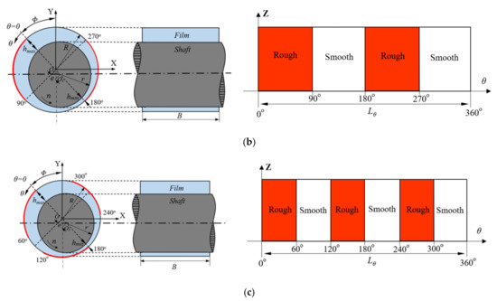
Figure 2.
Three types of heterogeneous rough/smooth bearing with different artificial roughness zones, (a) one-rough zone (1 L); (b) two-rough zones (2 L); (c) three-rough zones (3 L).

Table 1.
Parameters of the model.
To ensure that the flow regime in the studied journal bearing is turbulent, the calculation is performed by comparing the critical Reynolds number and the real Reynolds number . For all values of eccentricity ratio considered here, the calculated real Reynolds number, Rer is always much larger than the critical one, Rec. For example, for the case of ε = 0.8, the Rer is 1575 which is much larger than the Rec of 0.32. From the physical framework, it means that turbulence may occur in the fluid film and thus, from the numerical framework, such turbulence phenomena must be modeled during the lubrication analysis to achieve accurate results.
3.2. Meshing
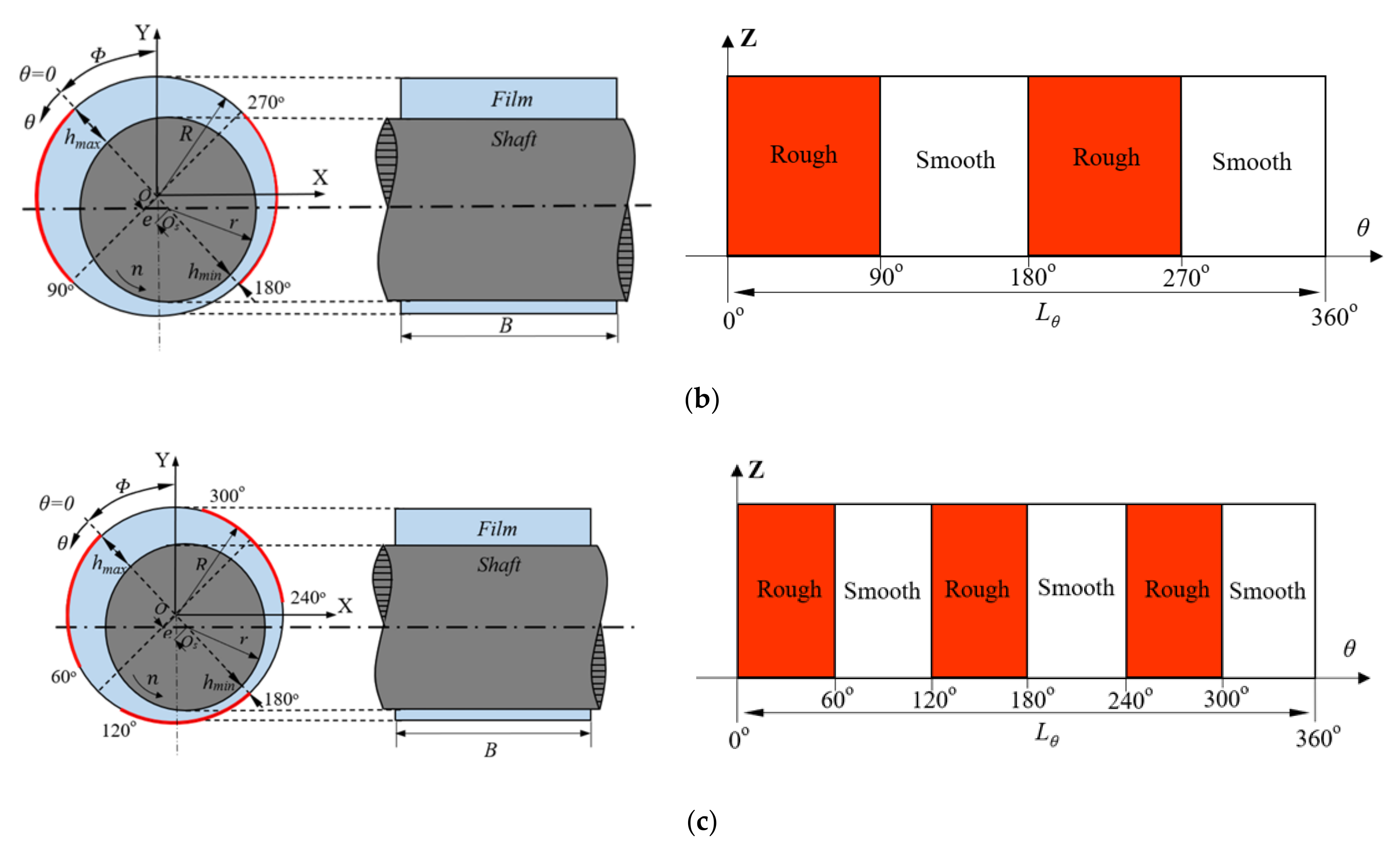
In this study, the mesh used consists of a uniform hexahedral grid. The face-meshing, edge-sizing and sweep-method features are used to form a mesh configuration. This results in the corresponding grid distribution being employed in the radial, circumferential and axial direction: 12 × 400 × 60. For all journal bearing configurations studied here, the mesh distribution is based on independent mesh results. As a note, the division of fluid layers taken after sensitivity analysis revealed that several values (12, 14, 16) of layers division change the chosen main parameter (load-carrying capacity in this case) by less than 2% in the CFD model. To conclude, the 12-layer division of fluid domain is employed for all simulations because it provides a reasonable computational time with a feasible level of independent mesh. In detail, the mesh configuration and the criteria of the mesh formed are shown in Figure 3 and Table 2 below. From Table 2, it can be observed that for all cases here, during the grid generation the average skewness is much lower than 0.25. This indicates that based on the skewness mesh metrics spectrum [29], the following mesh distributions are categorized as excellent and thus the discretization error due to the mesh generation can be prevented.

Figure 3.
Mesh of the computational domain.
Table 2.
Specification of the domain meshing.
3.3. Assumption and Boundary Condition
In this study, the journal moves with the shaft rotational speed n relative to the stationary bearing surface. Simulations are carried out using pressure-inlet and pressure-outlet boundary conditions. The values of the pressure at the inlet and outlet are taken as the ambient pressure, i.e., zero pressure. For moving wall boundary conditions, the surface is set to a rotating speed of 2000 rpm. In this research, the no-slip boundary condition is applied to the entire surface. In detail, Table 3 shows the boundary conditions used for the entire simulation case, whereas the setup of boundary conditions for the computational domain is depicted in Figure 4.
Table 3.
Boundary condition.
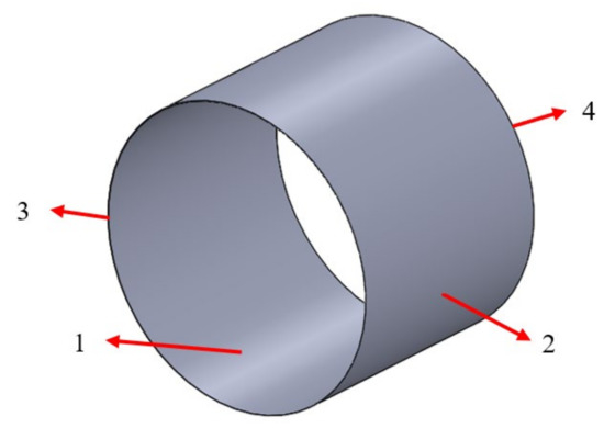
Figure 4.
Boundary condition of the computational domain: 1—moving wall, 2—stationary wall, 3–inlet, 4—outlet.
3.4. Solution Setup
In the present study, the governing equations for the fluid domain are discretized by the finite volume method using ANSYS FLUENT. To obtain an accurate pressure, the SIMPLE scheme is employed for the velocity–pressure coupling. For the momentum and volume fraction equations, a first-order upwind discretization scheme is employed. For spatial discretization of the turbulent kinetic energy and turbulent dissipation rate, the second-order upwind discretization scheme is chosen.
4. Results and Discussion
4.1. Validation
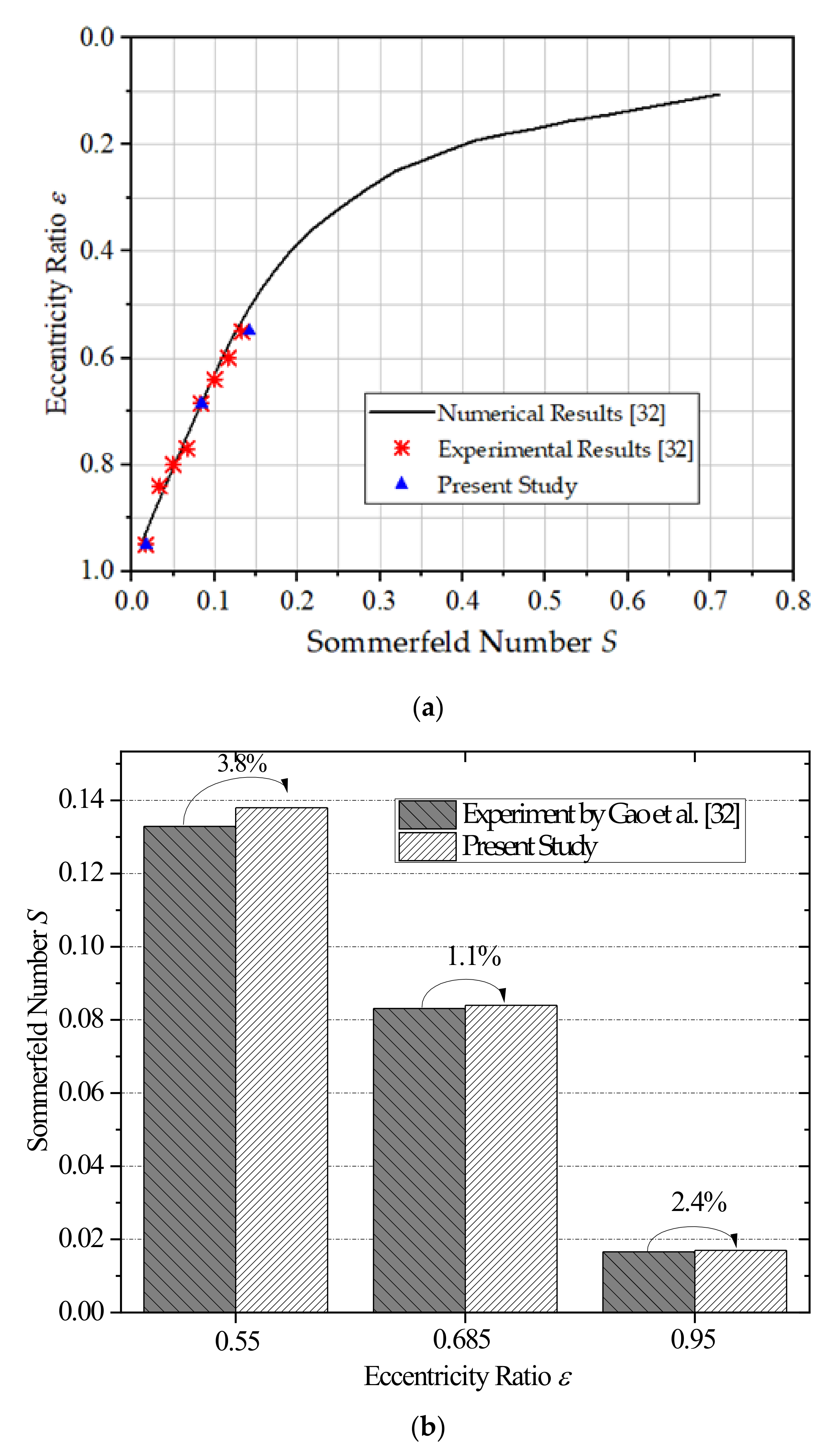
To confirm that the developed CFD model and its solution setup are valid with appropriate accuracy, in this section, a comparison study between the present study and the reference is conducted in terms of the Sommerfeld number S in which . Here, the result is compared with the numerical and experimental data of Gao et al. [32] under the same input conditions and computed operational parameters (i.e., ε = 0.55, ε = 0.685, and ε = 0.95, D = 80 mm, B = 80 mm, c = 0.08 mm, = 63.95°, n = 500–4000 rpm, μ = 0.001 Pa.s, ρ = 998.2 kg/m3), as reflected in Figure 5. It can be found that the obtained values from the CFD code developed here are very close to the published ones both from the numerical and experimental results. Their deviations are less than 4% as indicated in Figure 5b, suggesting validation of the developed CFD code.
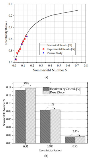
Figure 5.
(a) Comparison between the result of the present study and the literature [32], and (b) histogram of deviation between the present result and the experiment of Gao et al. [32].
4.2. At Varied Eccentricity Ratio
In application, the bearing performance is notably affected by the eccentricity ratio, representing the magnitude of the loading during operation. Thus, in this work, the prediction of the acoustic and tribological performance is made for different eccentricity ratios ε, i.e., 0, 0.1, 0.2, 0.3, 0.4, 0.5, 0.6, 0.7, and 0.8. The range of eccentricity ratio chosen here may accommodate the range of bearing loading from very low to heavy loadings. All computational results presented here are evaluated at a rotational speed of 2000 rpm with a surface roughness level Ra of 25 μm. As a note, the surface with a value Ra of 25 μm is categorized as “rough” surface (Ra = 12.5–100 μm) [33]. As demonstrated by Tauviqirrahman et al. [17], the surface class of “rough” has the strongest effect on the tribological performance [17] in comparison to other classes such as precision (Ra = 0.1–0.2 μm), fine (Ra = 0.4–0.8 μm), and medium (Ra = 1.6–6.3 μm).
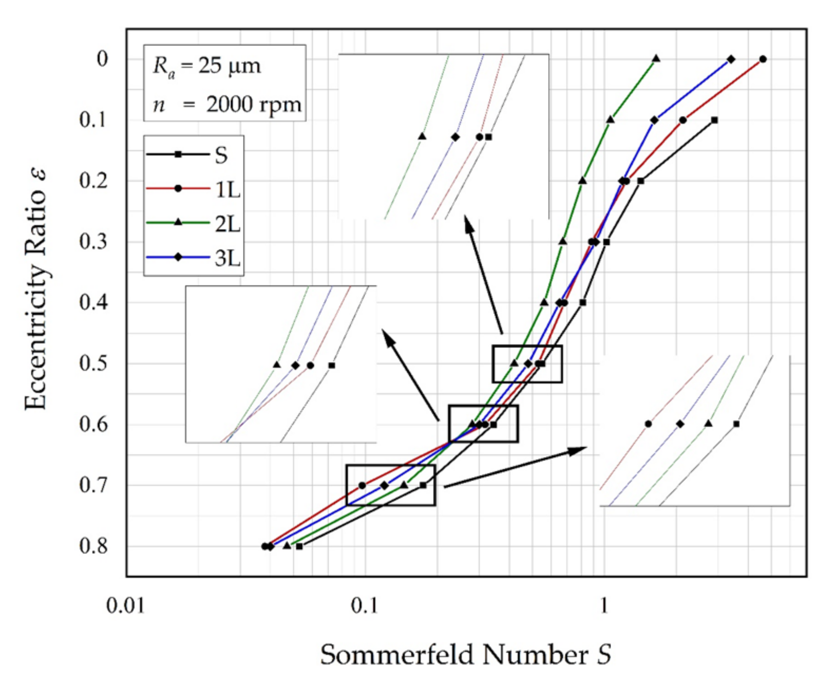
To show the effect of an engineered rough pattern on bearing characteristics, a plot of eccentricity ratio versus Sommerfeld number for both a conventional bearing (Ra = 0 and denoted as S pattern) and the bearing with the heterogeneous rough/smooth area (i.e., 1 L, 2 L, 3 L patterns) is reflected in Figure 6. From Figure 6, several characteristics can be seen. First, for all cases, an increase in the eccentricity ratio will decrease the Sommerfeld number S. The decrease in the Sommerfeld number occurs significantly when the eccentricity ratio ε is greater than 0.2. Secondly, when ε = 0 to 0.6, the heterogeneous rough/smooth bearing pattern with two-rough zones (2 L) gives the lowest Sommerfeld Number value when compared with the conventional smooth bearing (S) pattern and other heterogeneous rough/smooth bearing patterns. However, for eccentricity ratios of 0.7 and 0.8, heterogeneous rough/smooth bearing with one-rough zone (1 L) gives the lowest Sommerfeld Number. In the other words, although not superior to all eccentricity ratios studied here, the 2 L pattern gives the best performance in reducing the Sommerfeld number, which means that the enhanced load-carrying capacity can be achieved. From the results depicted in Figure 6, it can also be observed that the heterogeneous rough/smooth bearing, irrespective of the rough patterns, can generate the load-carrying capacity for all values of eccentricity ratio including for the concentric position. As is known, for the conventional bearing, no load-carrying capacity is produced when the concentric condition is applied due to the absence of the hydrodynamic pressure. This finding is interesting, and hence, the heterogeneous rough/smooth bearing can be compared to the heterogeneous slip/no-slip pattern. Based on the reference [19,22], even though there is no wedge effect in the case of concentric journal bearing, the heterogeneous slip/no-slip pattern could produce a relatively high load-carrying capacity. It indicates that the behavior of a “rough” surface can be correlated to the wettability of the surface (in particular the surface with hydrophobic coating) inducing the slip boundary. This is understandable because as discussed by Patankar [34] and Jung and Bhushan [35], the wettability of a surface is a function of its roughness.
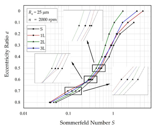
Figure 6.
Eccentricity ratio vs. Sommerfeld number. Note: Ra = 25 μm.
As observed in Figure 6, in terms of the Sommerfeld number, the 2 L pattern is superior for the case of low to medium loading, while the 1 L pattern is more appropriate to the case of higher loading. To further explore the positive effect of the application of an engineered rough surface of 1 L and 2 L patterns, the comparison of the performance between the conventional (smooth) bearing and the heterogeneous rough/smooth one is presented. Here, in the following computation, the performance ratio is introduced and defines the ratio of the hydrodynamic parameters (i.e., load-carrying capacity, friction force, and acoustic power level) predicted for the heterogeneous rough/smooth surface against that of a classical (smooth) surface. Figure 7, Figure 8 and Figure 9 summarize the ratio of the hydrodynamic performance parameters with a heterogeneous rough/smooth surface to that without a rough zone.
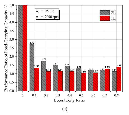
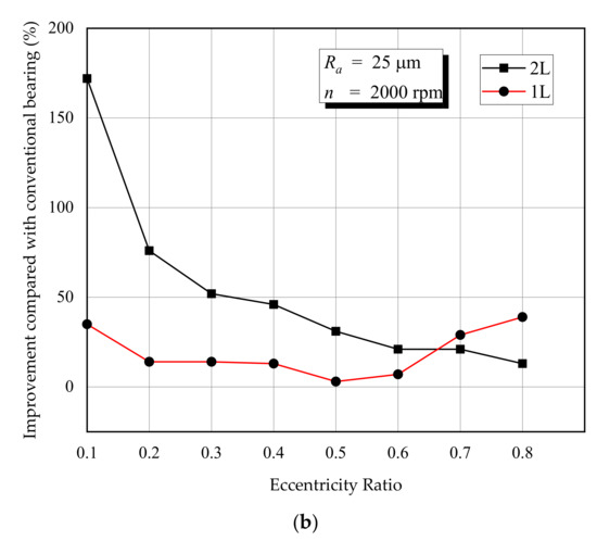
Figure 7.
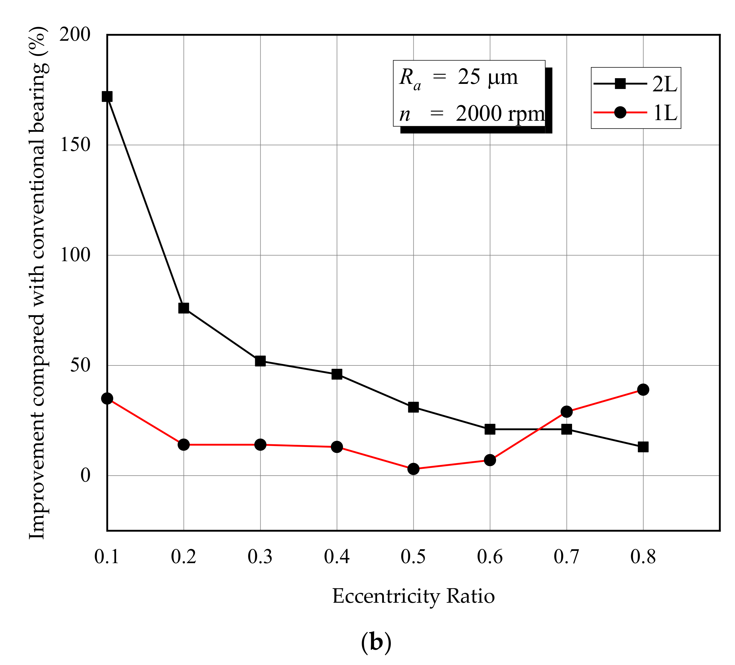
Effect of the arrangement of the rough zone on the load-carrying capacity under several eccentricity ratios, (a) lubrication performance ratio of load-carrying capacity, (b) improvement of the load-carrying capacity (compared with conventional bearing).
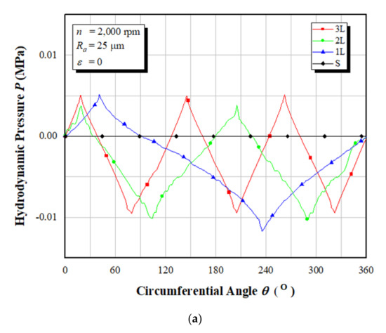
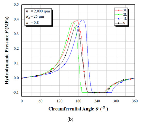
Figure 8.
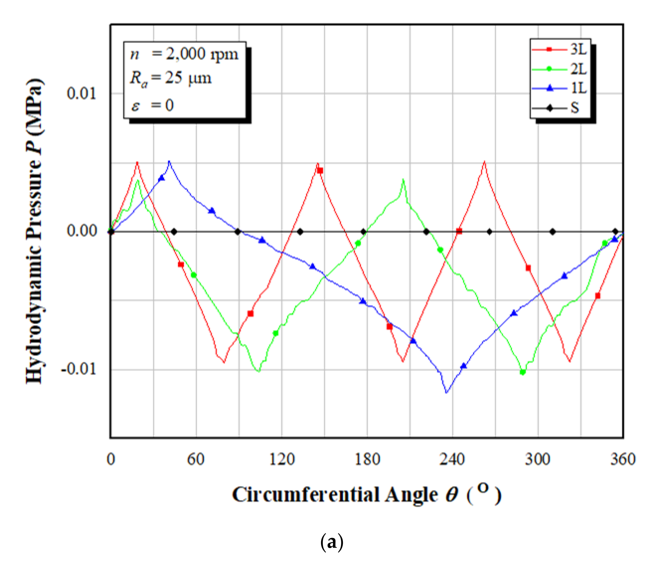
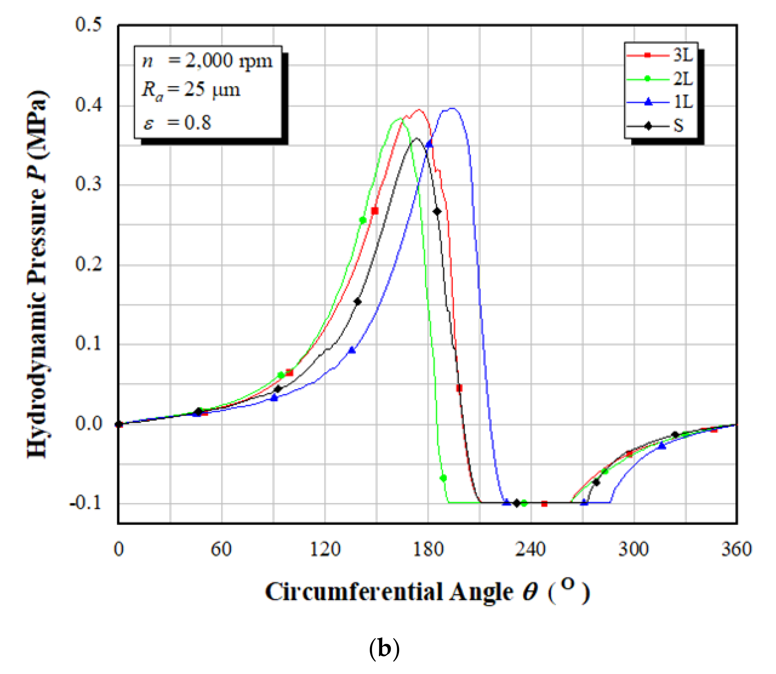
Hydrodynamic pressure distributions of the heterogeneous rough/smooth bearings for (a) ε = 0, and (b) ε = 0.8. The results are evaluated at the mid-plane of the bearing.
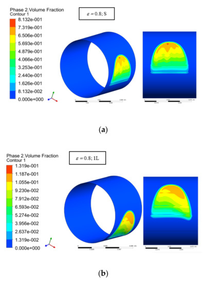
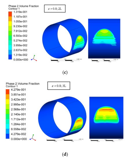
Figure 9.
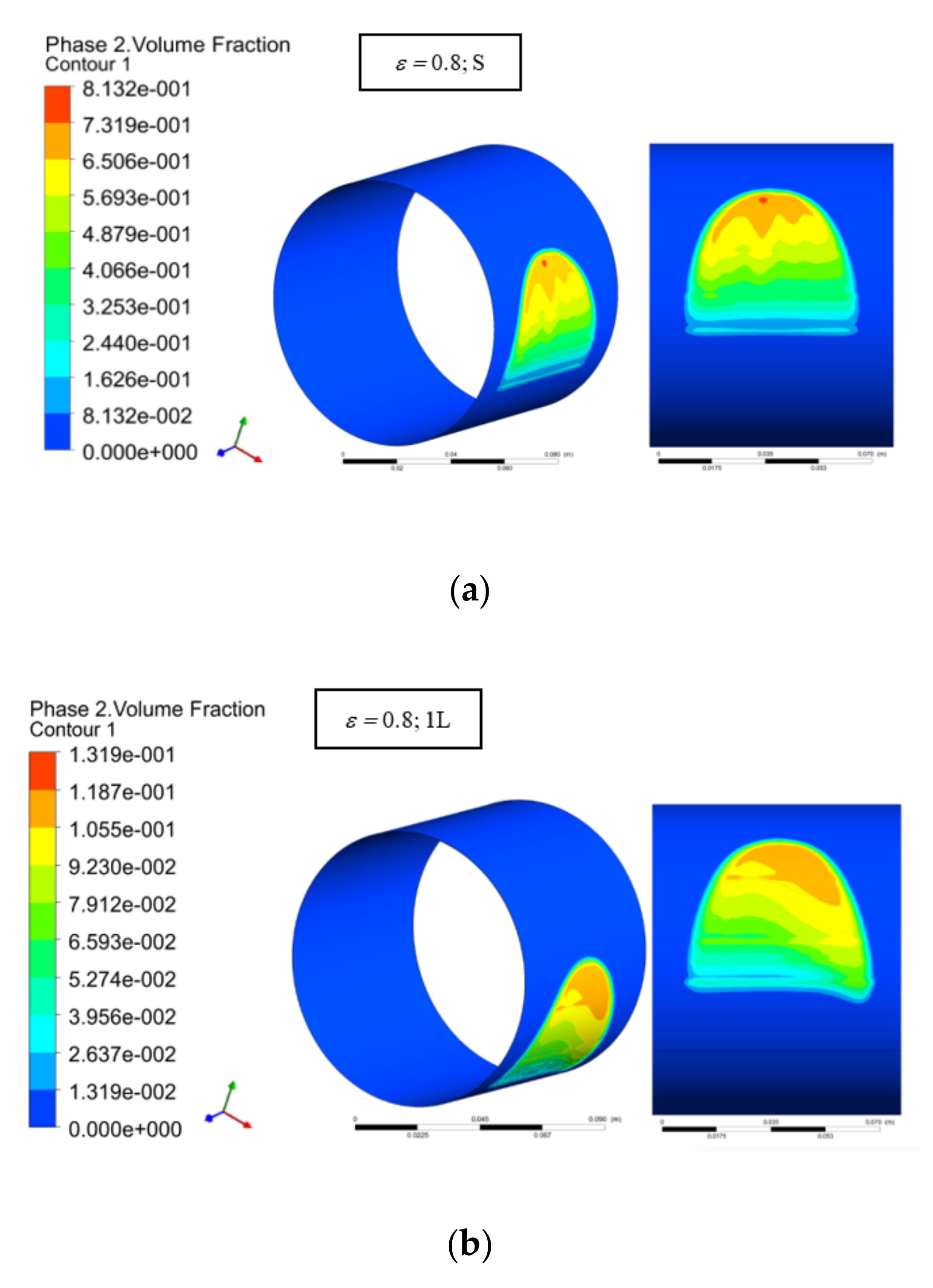
Comparison of the contour of vapor volume fraction between (a) the conventional (smooth) bearing, (b) the heterogeneous slip/no-slip bearing with 1L pattern, (c) the heterogeneous slip/no-slip bearing with 2 L pattern, (d) the heterogeneous slip/no-slip bearing with 3 L pattern.
Figure 7 shows the performance ratio of the load-carrying capacity for 1 L and 2 L patterns varying by eccentricity ratios. As a note, in Figure 7 the 3 L pattern is excluded because as depicted in Figure 6, the 3 L has a severe behavior in terms of Sommerfeld number compared to the other patterns. From Figure 7, the following features can be drawn. First, the values of the performance ratio for the heterogeneous rough/smooth bearings (1 L and 2 L) have a value above one which indicates that the load-carrying capacity of the two models is better when compared to the conventional (smooth) model for all eccentricity ratios considered here. It can also be drawn from Figure 7 that the benefit of heterogeneous rough/smooth patterns decreases with increased eccentricity ratio. Once again, this behavior seems to be similar to the behavior of the journal bearing with a heterogeneous slip/no-slip pattern. As discussed by several researchers focusing on the application of the heterogeneous slip/no-slip bearing, for example, Fortier and Salant [19], and Cui et al. [23], the eccentricity ratio reduces the positive effect of the applied engineered slip surface. In other words, the larger effect of the heterogeneous rough/smooth pattern can be achieved if the wedge effect is reduced. Second, the ratio of the load-carrying capacity of the 2 L model to the smooth model is higher at an eccentricity ratio from 0.1 to 0.6. For the eccentricity ratios of 0.7 and 0.8, the 1 L model has a higher performance ratio. This result is consistent with the previous finding as shown in Figure 6 in terms of Sommerfeld Number. This is understandable because the value of the load-carrying capacity of a journal bearing is inversely proportional to the value of the Sommerfeld Number. Third, it should be noted that as reflected in Figure 7, for the case of concentric position (ε = 0), the conventional (smooth) bearing cannot support the load, and as a consequence the value of the performance ratio of the load-carrying capacity for two models becomes infinite. From Figure 7, it is confirmed that the heterogeneous rough/smooth pattern in the concentric position of the journal bearing can support a load of 6.2 N for 1 L, and 17.53 N for 2 L. Once again, this indicates that the application of rough/smooth patterns can be promising in low loading operational condition.
Fourth, the differences in the placement and number of the rough zone for the design of the heterogeneous rough/smooth patterns have an impact on the load-carrying capacity of a journal bearing. For ε = 0.1, the performance ratio of the 2 L model is 101.8% higher than that of the 1 L model. At the medium loading position, say ε = 0.4, the 2 L model has a higher performance ratio of 54.8% when compared to the 1 L model. At the heavy loading position, i.e., ε = 0.8, the 1 L model has an increase in bearing performance which is 23.1% higher than the 2 L model. This result strengthens the findings highlighted in Figure 6, that the 2 L model is superior for the eccentricity ratios from 0 to 0.6.
The question “why do the different patterns of heterogeneous rough/smooth bearings bring out the different conclusions of load-carrying capacity” arises. The main contribution of the load-carrying capacity generations may give us a further understanding of this behavior. Figure 8 depicts the hydrodynamic pressure distribution for either conventional bearings or heterogeneous rough/smooth bearings for the concentric and non-concentric situations. Here, a high eccentricity ratio (ε = 0.8) is employed to explore the correlation of the wedge effect and the roughness effect. Through observation of Figure 8, one can observe that while the conventional bearing does not generate the lubrication performance in concentric condition, at the same condition the heterogeneous rough/smooth bearing can support the load irrespective of the rough zone. The capability of the heterogeneous rough/smooth bearing to build up the pressure is also found for the operation with a high eccentricity ratio. It is interesting to note that for the case of ε = 0.8, the profile of hydrodynamic pressure for the conventional bearing is similar to the heterogeneous rough/smooth bearings in the value of the peak pressure. The difference lies in the value of the maximum pressure and the width of the cavitation zone. However, such a difference is relatively small, as can also be observed in Figure 9, reflecting the comparison of the contour of vapor volume fraction between the conventional (smooth) bearing and the heterogeneous rough/smooth bearings. As mentioned earlier, the multi-phase cavitation model adopted here allows for phase change in a cavitation process. When the lubricant enters the divergent zone, the film pressure might fall below the saturation vapor pressure psat, and the lubricant would rupture. In the present study, the saturation pressure Psat used is 2340 Pa (as shown in Table 1), and the pressure at the inlet and outlet boundaries are taken as the ambient pressure, i.e., zero pressure. As a consequence, for each value of local pressures in the computational domain, FLUENT will reduce them with the environmental pressure patm of 1 atm (101,325 Pa). Therefore, when the cavitation occurs, the local pressure will be set to the saturation pressure (2340 Pa). By FLUENT, these values are converted to the negative value, i.e., −98,985 Pa (−0.1 MPa), as depicted in Figure 8, to show that the cavitation exists. Based on Figure 8b and Figure 9, when the eccentricity ratio is 0.8, the width of the cavitation zone does not change very much. It ranges from 50–70° depending on the bearing pattern. For example, in the case of 2 L pattern, the cavitation occurs at the circumferential angle θ of around 190°–236°.
Based on Figure 8, it is observed that for the case of a heterogeneous rough/smooth bearing with the 2 L pattern, the predicted maximum pressure is 11% higher compared with the conventional bearing. It indicates that for the same eccentricity ratio, the bearing with an engineered rough pattern can sustain a higher load than a conventional bearing. Again, this result strengthens the hypothesis proposed that the concept of heterogeneous rough/smooth bearings is very similar to the heterogeneous slip/no-slip pattern concerning how the heterogeneous rough/smooth bearing produces the load-carrying capacity. Fortier and Salant [19] found that the bearing with slip yields a lower Sommerfeld number (or higher load-carrying capacity) than the corresponding conventional bearing with the same eccentricity ratio. It is also confirmed from Figure 8 that, unlike the case with high ε, the pressure profiles are strongly affected by the placement and the number of the rough zones for the case with low ε. For example, for the 3 L pattern, three peak pressures can be observed following the number of rough zones. However, when the ε is increased to be very high (ε = 0.8 in this case), the 3 L pattern produces only one peak pressure for high. This means that the effect of the heterogeneous rough/smooth surface decreases with increased wedge effect. Again, this characteristic can be compared to the one with a heterogeneous slip/no-slip surface.
In terms of friction force, the effects of the application of 1 L and 2 L heterogeneous rough/smooth bearings are reflected in Figure 10. Specific features can be observed based on Figure 10. First, unlike the load-carrying capacity, the engineered rough zone leads to greater friction force compared to the conventional bearing. Compared to conventional journal bearings, the friction force of the heterogeneous rough/smooth bearing is 11–32% higher depending on the eccentricity ratio and the rough pattern (i.e., location and number). In other words, the application of the rough zone leads to a negative effect on friction. Second, concerning the eccentricity ratio effect, the performance ratio of frictional force for the 2 L and 1 L models does not change very much as the eccentricity ratio increases. The numerical results indicate that the use of the 2 L pattern consistently generates around 12% lower friction force compared with the 1 L bearing irrespective of the eccentricity ratio.
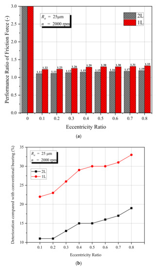
Figure 10.
Effect of the arrangement of the rough zone on friction force under several eccentricity ratios, (a) lubrication performance ratio of friction force, (b) deterioration of the friction force (compared with conventional bearing).
Concerning the question of “which is the best pattern to be used in journal bearing”, it seems that, based on the tribological point of view, the 2 L pattern gives the most benefits of performance. Although greater friction is observed at the 2 L configuration, in comparison with the conventional bearing, the benefit in enhancing the load-carrying capacity is very significant. As a note, as is reflected in Figure 7b, a 180% improvement in load-carrying capacity can be achieved by the heterogenous rough/smooth bearing with the 2 L pattern. However, as is known in reality, the condition of a lubricated bearing with high load-carrying capacity and low friction is the main indicator of a “good” bearing including the heterogeneous rough/smooth bearing. Therefore, for future work, the issue of how to reduce the friction force by heterogeneous rough/smooth bearing will be explored more extensively.
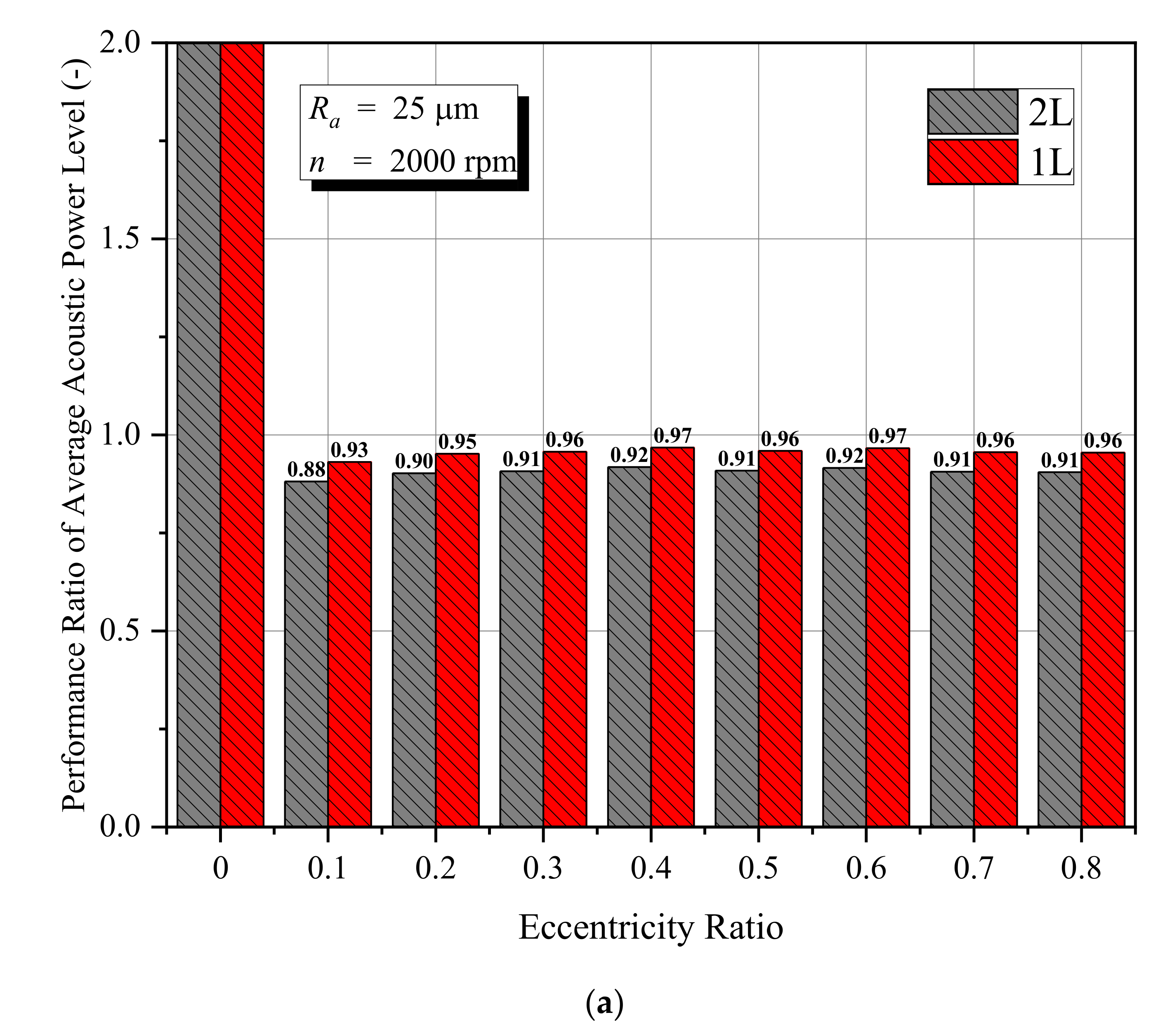
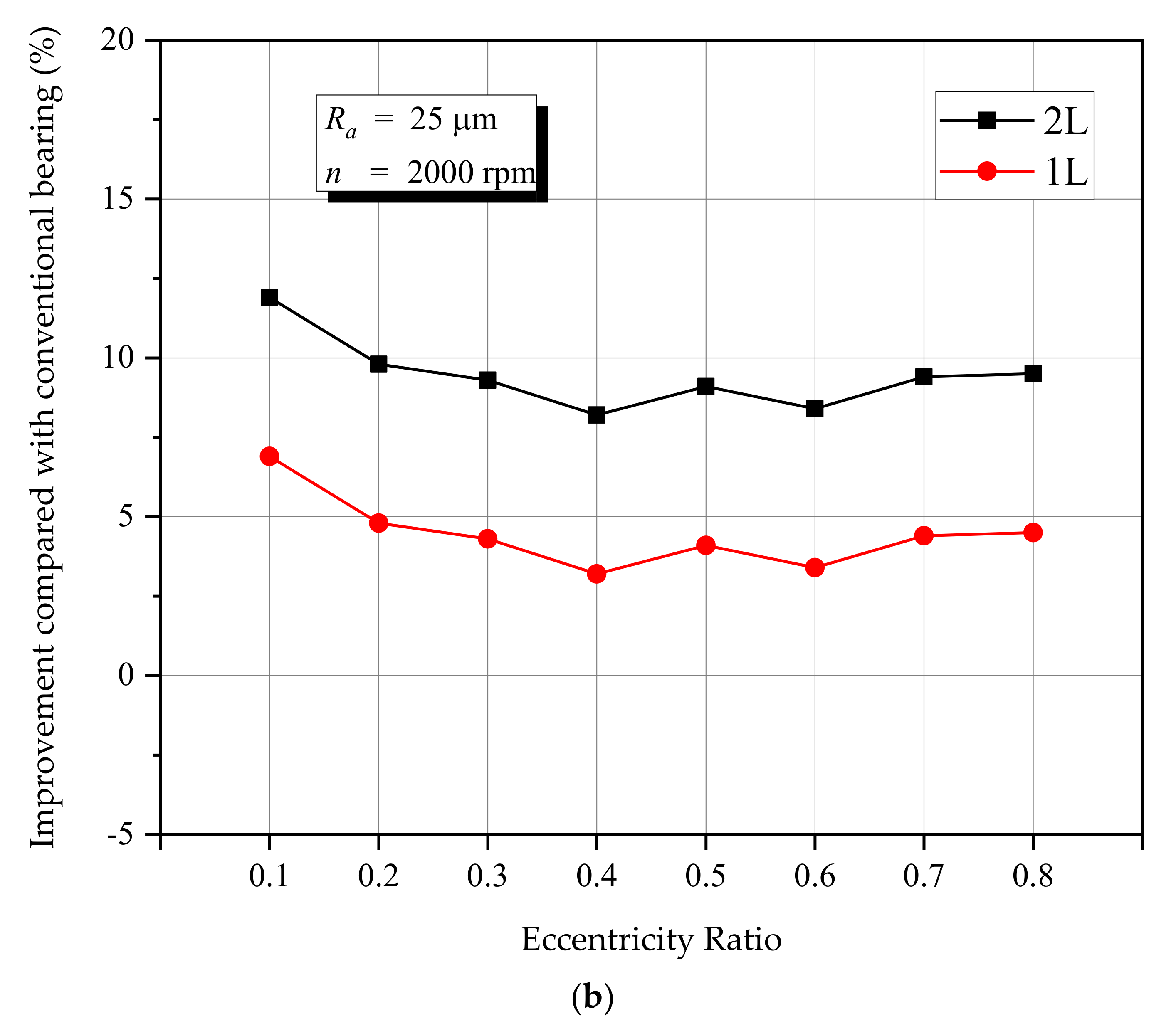
Concerning the acoustic performance, it is interesting to explore the characteristics of the main indicator of the bearing noise, namely, the average acoustic power level. For the researchers, the reduction in the average acoustic power level is considered as standard for enhancing the acoustic performance of contacting pairs. Is the average acoustic power level affected by the engineered rough surface? Is it significant or not? To answer these questions, the histogram of the performance ratio of the average acoustic power level versus the eccentricity ratio is presented in Figure 11a, while in Figure 11b, the enhancement of the acoustic power level by the heterogeneous rough/smooth patterns is shown. It should be noted that for an eccentricity ratio of 0 (i.e., concentric position), the conventional (smooth) bearings do not have a level of acoustic strength inducing the infinite value of the performance ratio for the two models. Based on Figure 11, it can be observed that the heterogeneous rough/smooth bearings bring out the improvement of the acoustic performance in terms of average acoustic power level irrespective of the rough zone placement. Compared with the conventional bearing, a 4–12% lower noise level can be achieved. Further, the numerical results show that the 2 L pattern produces a 5% lower average acoustic power level compared to the 1 L pattern for all eccentricity ratios. This indicates that reasonably engineering a rough zone position is essential in reducing the bearing noise. Additionally, these results also strengthen the previous result concerning the positive effect of the 2 L pattern application in enhancing load-carrying capacity.

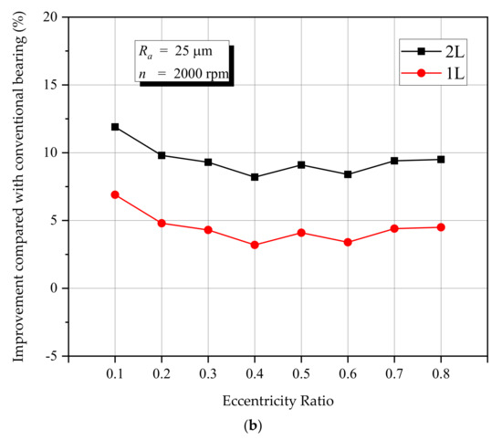
Figure 11.
Effect of the arrangement of the rough zone on average acoustic power level under several eccentricity ratios, (a) lubrication performance ratio of average acoustic power level, (b) improvement of the average acoustic power level (compared with conventional bearing).
5. Conclusions
The current work presents the benefit of a well-chosen heterogeneous rough/smooth surface on the acoustic and tribological performance of the journal bearing. Three alternatives of placement of a rough-smooth zone to create the heterogeneous rough/smooth bearing are studied in terms of average acoustic power level, load-carrying capacity, and friction force. In general, the results show that a journal bearing with a heterogeneous rough/smooth pattern has an advantage over a conventional bearing irrespective of the rough pattern in terms of load-carrying capacity and average acoustic power level. The effect of heterogeneous rough/smooth patterns is more dominant for low and moderate eccentricity ratios. Specifically, more enhanced load-carrying capacity and reduced average acoustic power level can be obtained through the two-rough zones (2 L) pattern. However, the numerical results also confirmed the drawback of the application of heterogeneous rough/smooth patterns. These patterns lead to up to 30% higher friction force in comparison to the conventional bearing. Therefore, for future work, the exploration of the optimal parameters of heterogeneous rough/smooth patterns focusing on how to reduce such friction should be performed.
Author Contributions
Conceptualization, M.T. and M.M.; Data curation, A.A.W.; Funding acquisition, J.J.; Project administration, S.S. and Y.N.; Software, M.M.; Supervision, J.J.; Validation, A.A.W. and C.P.; Visualization, M.T. and A.A.W.; Writing—review and editing, M.T. All authors have read and agreed to the published version of the manuscript.
Funding
This research is fully funded by RPI Grant, No. 233-29/UN7.6.1/PP/2021.
Data Availability Statement
The data presented in this study are available on request from the corresponding author.
Acknowledgments
The authors fully acknowledged Institute for Research and Community Services (LPPM), Diponegoro University for the approved fund which makes this important research viable and effective.
Conflicts of Interest
The authors declare no conflict of interest.
Nomenclature
| Local speed of the sound | |
| B | Bearing width |
| c | Radial clearance |
| Cs | Roughness constant |
| D | Bearing diameter |
| E | Empirical constant |
| fr | Roughness function |
| Fevap | Evaporation coefficient |
| Fcond | Condensation coefficient |
| hmin | Minimum film thickness |
| hmax | Maximum film thickness |
| Ks | Roughness height |
| k | Turbulent kinetic energy |
| l | Length scale |
| Lθ | Circumferential length of the bearing |
| n | Rotational speed |
| p | Hydrodynamic pressure |
| PA | Acoustic power level |
| psat | Saturation pressure |
| W | Load-carrying capacity |
| r | Shaft radius |
| R | Bearing radius |
| Ra | Arithmetic average of the roughness profile |
| RB | Bubble radius |
| Rec | Critical Reynolds number |
| Rer | Real Reynolds number |
| Rg, Rc | Mass transfer between the liquid and vapor phase |
| up | Mean velocity of the fluid at the near-wall node P |
| u* | dimensionless velocity |
| yp | Distance from point P to the wall |
| αnuc | Nucleation site volume fraction |
| αv | Vapor volume fraction |
| ε | Eccentricity ratio |
| εd | Turbulent dissipation rate |
| von Karman constant | |
| Circumferential angle | |
| µ | Lubricant viscosity |
| µv | Vapor viscosity |
| ρ | Lubricant density |
| ρv | Vapor density |
| Attitude angle |
References
- Malcolm, E.; Leader, P.E. Understanding Journal Bearings; Applied Machinery Dynamics, Co.: Durango, CO, USA, 2001. [Google Scholar]
- Tala-Ighil, N.; Fillon, M.; Maspeyrot, P. Effect of textured area on the performances of a hydrodynamic journal bearing. Tribol. Int. 2011, 44, 211–219. [Google Scholar] [CrossRef]
- Brizmer, V.; Kligerman, Y. A laser surface textured journal bearing. J. Tribol. 2012, 134, 031702. [Google Scholar] [CrossRef]
- Ji, J.; Fu, Y.; Bi, Q. Influence of geometric shapes on the hydrodynamic lubrication of a partially textured slider with micro-grooves. J. Tribol. 2014, 136, 041702. [Google Scholar] [CrossRef]
- Meng, F.M.; Zhang, L.; Liu, Y.; Li, T.T. Effect of compound dimple on tribological performances of journal bearing. Tribol. Int. 2015, 91, 99–110. [Google Scholar] [CrossRef]
- Meng, F.M.; Wei, Z.; Minggang, D.; Gao, G. Study of acoustic performance of textured journal bearing. Proc. Ins. Mech. Eng. Part J J. Eng. Tribol. 2016, 230, 156–169. [Google Scholar] [CrossRef]
- Meng, F.M.; Zhang, W. Effects of compound groove texture on noise of journal bearing. J. Tribol. 2017, 140, 031703. [Google Scholar] [CrossRef]
- Meng, F.; Yu, H.; Gui, C.; Chen, L. Experimental study of compound texture effect on acoustic performance for lubricated textured surfaces. Tribol. Int. 2019, 133, 47–54. [Google Scholar] [CrossRef]
- Wang, J.; Zhang, J.; Lin, J.; Ma, L. Study on lubrication performance of journal bearing with multiple texture distributions. Appl. Sci. 2018, 8, 244. [Google Scholar] [CrossRef] [Green Version]
- Manser, B.; Belaidi, I.; Khelladi, S.; Chikh, M.A.A.; Deligant, M.; Bakir, F. Computational investigation on the performance of hydrodynamic micro-textured journal bearing lubricated with micropolar fluid using mass-conserving numerical approach. Proc. Ins. Mech. Eng. Part J J. Eng. Tribol. 2020, 234, 1310–1331. [Google Scholar] [CrossRef]
- Saleh, A.M.; Crosby, W.; El Fahham, I.M.; Elhadary, M. The effect of liner surface texture on journal bearing performance under thermo-hydrodynamic conditions. Ind. Lub. Tribol. 2020, 72, 405–414. [Google Scholar] [CrossRef]
- Javorova, J. EHD lubrication of journal bearings with rough surfaces. In Proceedings of the International Conference “Mechanical Engineering in XXI Century”, Nis, Serbia, 25–26 November 2010. [Google Scholar]
- Hsu, T.C.; Chen, J.H.; Chiang, H.L.; Chou, T.L. Lubrication performance of short journal bearings considering the effects of surface roughness and magnetic field. Tribol. Int. 2013, 61, 169–175. [Google Scholar] [CrossRef]
- Kalavathi, G.K.; Dinesh, P.A.; Gururajan, K. Influence of roughness on porous finite journal bearing with heterogeneous slip/no-slip surface. Tribo. Int. 2016, 102, 174–181. [Google Scholar] [CrossRef]
- Cui, S.; Gu, L.; Fillon, M.; Wang, L.; Zhang, C. The effects of surface roughness on the transient characteristics of hydrodynamic cylindrical bearings during startup. Tribol. Int. 2018, 128, 421–428. [Google Scholar] [CrossRef]
- Abd Al-Samieh, M.F. Surface roughness effects for Newtonian and non-Newtonian lubricants. Tribol. Ind. 2019, 41, 56–63. [Google Scholar] [CrossRef]
- Tauviqirrahman, M.; Ichsan, B.C.; Jamari, M. Influence of roughness on the behavior of three-dimensional journal bearing based on fluid-structure interaction approach. J. Mech. Sci. Technol. 2019, 33, 4783–4790. [Google Scholar] [CrossRef]
- Gu, C.; Meng, X.; Wang, S.; Ding, X. Study on the mutual influence of surface roughness and texture features of rough-textured surfaces on the tribological properties. Proc. Ins. Mech. Eng. Part J. J. Eng. Tribol. 2021, 235, 256–273. [Google Scholar] [CrossRef]
- Fortier, A.E.; Salant, R.F. Numerical analysis of a journal bearing with a heterogeneous slip/no-slip surface. J. Tribol. 2005, 127, 820–825. [Google Scholar] [CrossRef] [Green Version]
- Lin, Q.; Wei, Z.; Zhang, Y.; Wang, N. Effects of the slip surface on the tribological performances of high-speed hybrid journal bearings. Proc. Ins. Mech. Eng. Part. J J. Eng. Tribol. 2016, 230, 1149–1156. [Google Scholar] [CrossRef]
- Bhattacharya, A.; Dutt, J.K.; Pandey, R.K. Influence of hydrodynamic journal bearings with multiple slip zones on rotordynamic behavior. J. Tribol. 2017, 139, 061701. [Google Scholar] [CrossRef]
- Wu, Z.; Ding, X.; Zeng, L.; Chen, X.; Chen, K. Optimization of hydrodynamic lubrication performance based on a heterogeneous slip/no-slip surface. Ind. Lubr. Tribol. 2019, 71, 772–778. [Google Scholar] [CrossRef]
- Cui, S.; Zhang, C.; Fillon, M.; Gu, L. Optimization performance of plain journal bearings with partial wall slip. Tribol. Int. 2020, 145, 106–137. [Google Scholar] [CrossRef]
- Tauviqirrahman, M.; Afif, M.F.; Paryanto, P.; Jamari, J.; Caesarendra, W. Investigation of the tribological performance of heterogeneous slip/no-slip journal bearing considering thermo-hydrodynamic effects. Fluids 2021, 6, 48. [Google Scholar] [CrossRef]
- Dhande, D.Y.; Pande, D.W. Multiphase flow analysis of hydrodynamic journal bearing using CFD coupled fluid structure interaction considering cavitation. J. King Saud Univ. Eng. Sci. 2018, 30, 345–354. [Google Scholar] [CrossRef] [Green Version]
- Morris, N.J.; Shahmohamadi, H.; Rahmani, R.; Rahnejat, H.; Garner, C.P. Combined experimental and multiphase computational fluid dynamics analysis of surface textured journal bearings in mixed regime of lubrication. Lubr. Sci. 2018, 30, 161–173. [Google Scholar] [CrossRef] [Green Version]
- Sun, D.; Li, S.; Fei, C.; Ai, Y.; Liem, R.P. Investigation of the effect of cavitation and journal whirl on static and dynamic characteristics of journal bearing. J. Mech. Sci. Technol. 2019, 33, 77–86. [Google Scholar] [CrossRef]
- Tauviqirrahman, M.; Jamari, J.; Wibowo, B.S.; Fauzan, H.M.; Muchammad, M. Multiphase computational fluid dynamics analysis of hydrodynamic journal bearing under the combined influence of texture and slip. Lubricants 2019, 7, 97. [Google Scholar] [CrossRef] [Green Version]
- ANSYS. ANSYS Fluent, Version 16.0: User Manual; ANSYS, Inc.: Canonsburg, PA, USA, 2017. [Google Scholar]
- Zwart, P.; Gerber, A.G.; Belamri, T. A two-phase flow model for predicting cavitation dynamic. In Proceedings of the Fifth International Conference on Multiphase Flow, Yokohama, Japan, 30 May 2004. [Google Scholar]
- Adams, T.; Grant, C.; Watson, H. A Simple algorithm to relate measured surface roughness to equivalent sand-grain roughness. Int. J. Mech. Eng. Mechatron. 2012, 1, 66–71. [Google Scholar] [CrossRef]
- Gao, G.; Yin, Z.; Jiang, D.; Zhang, X.; Wang, Y. Analysis on design parameters of water-lubricated journal bearings under hydrodynamic lubrication. Proc. Inst. Mech. Eng. Part J J. Eng. Tribol. 2016, 230, 1019–1029. [Google Scholar] [CrossRef]
- Japanese Industrial Standard/Japanese Standards Association. JIS B 0601:2013 Geometrical Product Specifications (GPS)—Surface Texture: Profile Method—Terms, Definitions and Surface Texture Parameters (Foreign Standard); Japanese Industrial Standard/Japanese Standards Association: Tokyo, Japan, January 2013. [Google Scholar]
- Patankar, N.A. On the modeling of hydrophobic contact angles on rough surfaces. Langmuir 2003, 19, 1249–1253. [Google Scholar] [CrossRef]
- Jung, Y.C.; Bhushan, B. Contact angle, adhesion and friction properties of micro and nanopatterned polymers for superhydrophobicity. Nanotechnology 2006, 17, 4970–4980. [Google Scholar] [CrossRef]


Publisher’s Note: MDPI stays neutral with regard to jurisdictional claims in published maps and institutional affiliations. |
© 2021 by the authors. Licensee MDPI, Basel, Switzerland. This article is an open access article distributed under the terms and conditions of the Creative Commons Attribution (CC BY) license (https://creativecommons.org/licenses/by/4.0/).