Article

Operating Behavior of Sliding Planet Gear Bearings for Wind Turbine Gearbox Applications—Part I: Basic Relations

Institute of Tribology and Energy Conversion Machinery, Clausthal University of Technology, 38678 Clausthal-Zellerfeld, Germany
*
Author to whom correspondence should be addressed.
Lubricants 2021, 9(10), 97; https://doi.org/10.3390/lubricants9100097
Submission received: 30 July 2021 / Revised: 15 September 2021 / Accepted: 21 September 2021 / Published: 1 October 2021
(This article belongs to the Special Issue Advances in Lubricated Bearings)

Abstract

:
The application of sliding planet gear bearings in wind turbine gearboxes has become more common in recent years. Assuming practically applied helix angles, the gear mesh of the planet stage causes high force and moment loads for these bearings involving high local loads at the bearing edges. Specific operating behavior and suitable design measures to cope with these challenging conditions are studied in detail based on a thermo-hydrodynamic (THD) bearing model. Radial clearance and axial crowning are identified as important design parameters to reduce maximum pressures occurring at the bearing edges. Furthermore, results indicate that a distinct analysis of the gear mesh load distribution is required to characterize bearing operating behavior at part-load. Here, operating conditions as critical as the ones reached at nominal load might occur. Wear phenomena can improve the shape of the gap in the circumferential as well as in axial direction incorporating a significant reduction of local maximum pressures. The complexity of the combination of these aspects and the additionally expected impact of structure deformation gives an insight into the challenges in the design processes of sliding planet gear bearings for wind turbine gearbox applications.

1. Introduction

Generally, two different design concepts exist for wind turbine power trains. The first one foregoes a transmission between rotor and generator, and therefore, generator speed equals the one of the main rotor. Whereas this direct drive design provides high robustness of the power train, it involves high demands on generator design as the rotating frequency of the main rotor is in the magnitude of 1% or even less of the net frequency. The second design approach applies a gearbox between the rotor and generator shaft, which increases the speed on the generator side and reduces the previously mentioned discrepancy to approximately 50%. This enables a more compact generator design. Both concepts feature specific advantages and disadvantages that are comprehensively discussed by Ragheb and Ragheb [1]. Gearboxes failures contribute 10% to 20% of wind turbine downtimes [2,3]. Most commonly, wind turbines gearboxes feature one or two planetary and one spur gear stage due to lightweight and compact design requirements. Here, gear tooth as well as bearing damages represent the main issues leading to downtimes [4]. In recent years, the application of sliding bearings in wind turbine power trains has become more common, in particular, in the case of the planet gear bearing. The sliding planet gear bearing requires less radial space than the conventionally used rolling element bearings and enables flexible modification of gear rim thickness. Moreover, it is not susceptible to typical damage mechanisms that occur in rolling bearings and are caused by excitation from the gear mesh. However, several challenging phenomena in low speed and high load planet gear bearings exist that are partly specific for this tribologic system and that have not been studied in detail yet.
Figure 1 explains the basic design of a typical planet stage for wind turbine gearbox applications investigated in this study. The torque generated by the kinetic energy of the wind drives the main rotor that is connected by a hub to the planet carrier. The carrier rotates with the main rotor speed. Most commonly, four or five planets are attached to the carrier and distribute the driving torque to the same number of mesh contacts. The planets rotate in a non-rotating ring gear due to the carrier speed and drive a sun gear that is connected to the output shaft of the planet stage. Torque decreases from the rotor to the generator side while rotating frequencies increase according to the particular transmission ratios. Commonly, additional gear stages follow this first low-speed stage.
Figure 2 shows the red signed forces on the planet as well as the yellow signed components of the mesh forces. In the case of the straight gear in Figure 2a, the mesh forces feature a tangential Ft and radial Fr component. As the sum of the radial force components is zero, the bearing force Fsc is equal to the sum of the tangential forces. Both components of the mesh force contribute to an oval deformation of the planet. The magnitude of the oval shape of deformation strongly depends on the ratio between mesh forces and rim thickness and influences the lifetime of rolling element bearings [5,6]. In the case of the helical gear in Figure 2b, additional axial force components Fax exist that involve a moment load about y-axis. This moment load Msc has to be restored by the contact pressure in the bearing and is a function of the helix angle of the helical gear. An additional moment about the x-axis occurs if the load distribution on the tooth flanks becomes inhomogeneous in the lateral direction and causes eccentric points of application of resulting mesh forces. Figure 2c depicts an assembled helical planet gear with its contact partners in the front view of a planet stage.
Restoring the moment load requires a significant misalignment between planet and pin to generate the moment by fluid and asperity pressure in the bearing contact. This creates a load condition that distinguishes the planet gear bearing from most other applications, which are primarily loaded by radial forces. Bouyer and Fillon [7] and Sun and Changlin [8] investigate the impact of misalignment between shaft and stator for journal bearings and report on the well-known effect of edge loading. Whereas Bouyer and Fillon [7] experimentally apply different vertical torque levels parallel to load direction, Sun and Changlin [8] theoretically study the impact of the same misalignment angle applied at different angular journal positions and variable eccentricities.
Depending on the concrete application, deformation can have positive as well as negative impact on the load-carrying capacity of sliding bearings. If elasto-hydrodynamic deformation is dominant, a rise of the film thickness compared to the hydrodynamic theory exists [9]. Conversely, Hagemann et al. [10] show a reduction of film thickness for a large five-pad tilting-pad journal bearing due to consideration of thermo-mechanical deformation in their analysis and validate the results with experimental data. This decrease in load capacity is traced to the thermally and mechanically induced axial bending of the tilting pads. Prölß [11] extends and adjusts the sliding bearing model presented by the authors in [10,12] to planet gear bearings. He determines a significant impact of deformation on predicted operating behavior due to the above-described load situation.
This investigation focuses on a basic understanding of the impact of different parameters on the operating behavior of sliding planet gear bearings as this type of bearing has received increasing importance, especially within recent years. While numerous publications on conventional journal bearings under low speed and high load conditions exist, e.g., [13,14,15], the specific properties of planet gear bearings have not been comprehensively described in the literature with the exception of [11] to the authors’ knowledge. However, understanding their specific kinematics, load situations, and deformation behavior is essential for the development of a robust planet gear bearing design, in particular in the case of helical gears. Many investigations focus on nominal or maximum load conditions but part- and under-load can also contribute bearing damages as Garabedian et al. [16] show for rolling element planet gear bearings of a wind turbine gearbox. Therefore, aspects of the impact of part-load conditions on the performance of sliding planet gear bearings are also studied. All subsequent analyses in the first part of this study assume rigid macro geometries for pin and planet, while the second part [17] focuses on the impact of structure deformation on predicted results. Moreover, all results represent static equilibriums and neglect dynamic force components that are of minor interest for the investigated load cases.

2. Materials and Methods

2.1. Governing Equations and Bearing Model

The authors describe the governing equations of the bearing model including the consideration of oil supply effects in [10,12]. The generalized average Reynolds Equation (1) for laminar flow is extended by the flow factors according to Patir and Cheng [18] to consider the impact of surface roughness on hydrodynamic flow in the thin film region. Due to the exclusive static load conditions investigated in this study, the squeeze term is neglected in Equation (1).
r j ϕ Φ x p · F 2 p h y d r j ϕ + z Φ z p · F 2 p h y d z = U p l a n e t r j ϕ Θ h F 1 F 0 U p l a n e t 2 Θ R q Φ x s r j ϕ
Herein, Φ x p and Φ z p are the pressure flow factors, and Φ x s is the shear flow factor. Equation (2) describes the local thickness of the lubricant gap h considering alignment angles between pin and pad φ x and φ z .
h ϕ , z = C R e · c o s ϕ γ + z · φ x · c o s ϕ + φ y · s i n ϕ + Δ h ϕ , z
In contrast to the conventional journal bearing, the outer solid body rotates, and the pin is fixed. Therefore, the pin features a stationary temperature profile whereas temperature in circumferential direction homogenizes in the planet due to sufficiently high rotational speeds. Equation (3) includes the governing equations of the temperature model of the planet gear bearing for its three components. Figure 3 visualizes the differences between the discretization of the solution domains of journal and planet gear bearing for the thermal bearing model.
Lubricant   gap :   c · ρ · u 1 r j T ϕ + v T y + w T z = η · u y 2 + w y 2 +          1 r j ϕ λ 1 r j T ϕ + y λ T y + z λ T z Pin :         1 r ϕ λ p i n 1 r T ϕ + 1 r r λ p i n r T r + z λ p i n T z = 0 Planet :       1 r r λ p l a n e t r T r + z λ p l a n e t T z = 0
Herein u, v, and w are the flow velocities in the lubricant gap. In comparison to the journal bearing, the three-dimensional part of the solution domain is adjusted to the new requirements and the interface of the three to the two-dimensional section of the solution domain is shifted from the journal radius in Figure 4a to the inner radius of the planet in Figure 4b. At each internal fluid–solid interface, conjugate heat transfer boundary conditions are valid. Temperature-dependent lubricant viscosity is determined using the dynamic viscosity η 0 at the reference temperature T 0 by the equation of Falz [19].
η T = η 0 · T T 0 l
A periodicity boundary condition in the circumferential direction is applied for the solution of Equation (1) and the three-dimensional parts of Equation (3) at the particular boundaries of the solution domain. Moreover, the thermal bearing model assumes convective heat transfer boundary conditions for the free solid body surfaces. For the solution of Reynolds and energy equation, a conservative finite difference scheme (Finite Volume Method (FVM)) is applied. The solution of the generalized average Reynolds Equation (1) is based on the difference scheme proposed by Elrod [20]. The combined convection and diffusion problem of the energy equation is stabilized by the Hybrid scheme according to the description in [21]. References [10,12] describe further details on numerical implementation, including flow charts of the entire numerical procedure.
The eccentricities ex, ey and angular alignment φx, φy between the centerlines of planet and pin are determined using stiffness matrix C defined by Equation (5) to minimize the error between mesh forces and bearing contact forces in order to find the static state of equilibrium. The coefficients of C represent the sum of hydrodynamic and solid contact stiffness coefficients in the mixed friction regime while solid contact stiffness is equal to zero in the hydrodynamic regime.
C = C x x C x y C y x C y y C x φ x C x φ y C y φ x C y φ y C φ x x C φ x y C φ y x C φ y y C φ x φ x C φ x φ y C φ y φ y x C φ y φ y = C h y d + C s o l i d
Hydrodynamic stiffness coefficients are derived from a linear perturbation of generalized average Reynolds Equation (1). For this purpose, a linear impact of film thickness modification on fluid film pressure due to translational (X,Y) or angular (φXY) rigid body displacements relative to the current position described by ex, ey, φx, and φy is assumed according to Equation (6).
h * ϕ , z = h ϕ , z + X sin ϕ + Y cos ϕ z · φ X . cos ϕ + z · φ Y sin ϕ
Solid body stiffness directly follows from the local gradient of the relation between the mean distance of the contact partners and the asperity contact forces. A highly time efficient iterative scheme based on the idea of Waltermann [22] and extended to consider moment loads adjusts solid body positions and minimizes the differences between the outer forces and moments and the ones restored by the fluid film and the solid contact pressure.
The authors comprehensively validated the theoretical THD bearing model and its implementation with test data in previous investigations for fixed-pad and tilting-pad journal bearings, e.g., [10,12,23]. As no test data for planet bearings is available, this step must be omitted here. However, the correct implementation of the impact of misalignment, which is of particular interest in this study, was not part of previous validation and is verified with data from the literature.

2.2. Verification of the Numerical Procedure

Results of Sun and Changlin [8] are used to verify the numerical implementation of the THD model in the planet gear bearing code with a special focus on misalignment. Table 1 includes the data of the investigated journal bearing.
Due to the isoviscous approach of the study, no impact of the modified kinematics in the planet gear bearing code has to be expected. Figure 5 shows excellent agreement between the two analyses for the local film pressure distribution in the case of the aligned bearing (a,b) as well as for the highest investigated level of misalignment (c,d). While maximum pressures in [8] are given with 33.06 MPa for the aligned case and 143.34 MPa for the misaligned case, they are predicted with 33.30 and 144.2 MPa in this study. Additionally, the resulting moments of the fluid forces due to different levels of misalignment in Figure 6 nearly match for both analyses and verify the basic implementation of the THD model in the planet gear bearing code.

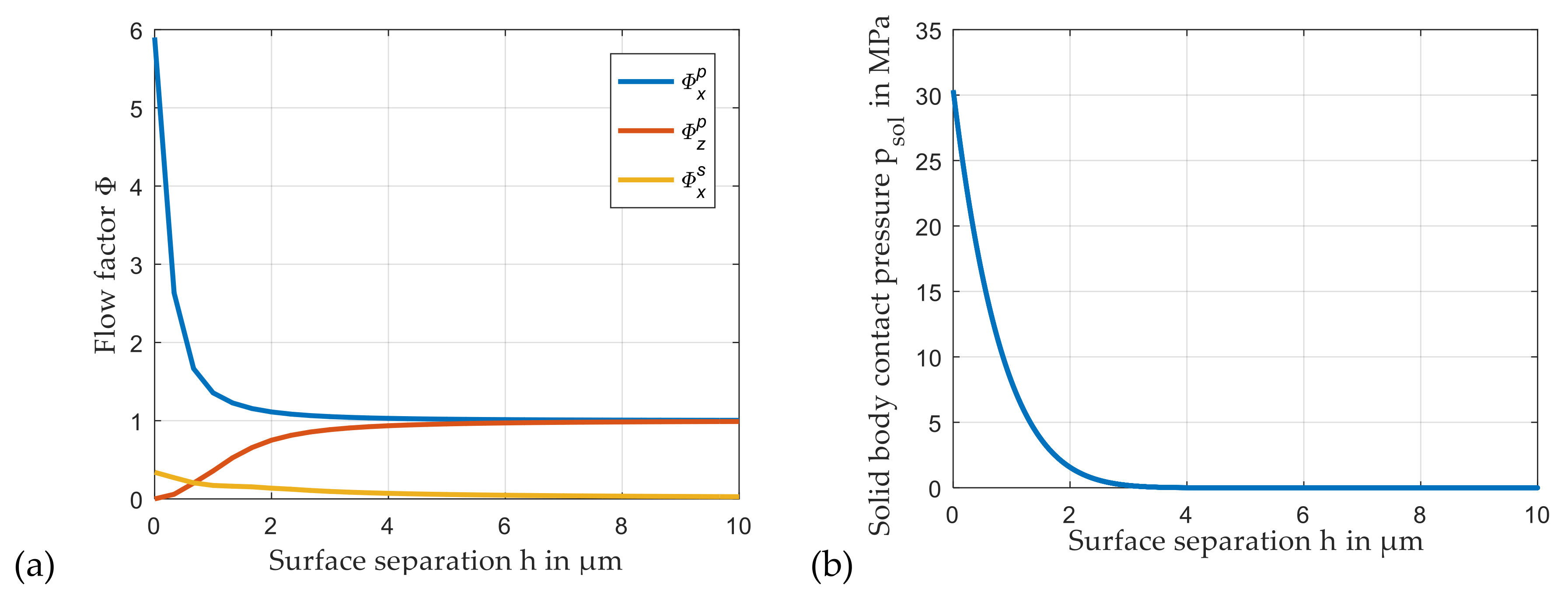
2.3. Flow Factors and Solid Contact Pressure

The detailed prediction of flow factors and solid body pressure is not an aim of this study. In fact, these parameters are introduced to apply a consistent bearing model with representative parameters. Flow factors are analyzed based on the average Reynolds equation according to [18]. Results are given in Figure 7a. An application of the theory of Greenwood and Williamson [24] provides a relation between the mean film thickness on the node of the numerical grid and solid contact pressure due to the interaction of the asperities that is shown in Figure 7b. The contact surface features a root mean square roughness value of Rq = 2.83 µm and matches the one earlier presented by the authors in [25]. A turning process generates the surface topography that features small grooves in the circumferential direction. Solid body contact pressure is determined based on the formula proposed by Hu et al. [26]. Consequently, it slightly deviates from the ones presented in [25], which are evaluated differently. The concrete course of the solid body load-carrying capacity has exemplary character in this investigation. Therefore, the contradiction that the theory of Greenwood and Williamson presupposes a normal distribution of the surface roughness that does not exist for the investigated contact surface is accepted here.

2.4. Investigated Sliding Planet Gear Bearing

Table 2 includes the basic analysis parameters of the investigated planet gear bearing. The values are of the typical magnitude of planet gear bearings applied in 3 MW wind turbine gearboxes.

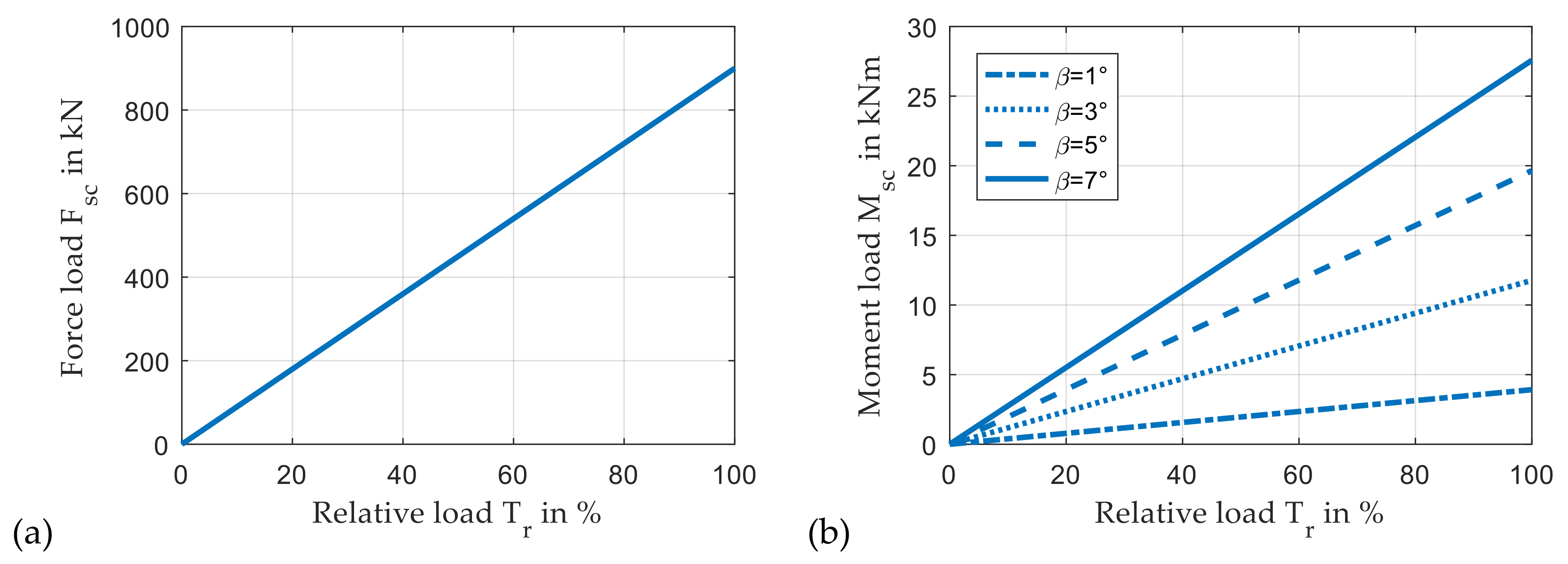
2.5. Bearing Loads Due to Mesh Forces

According to the illustrations in Figure 2, the mesh forces generate the load of the planet gear bearing. The static radial bearing load Fsc is equal to the sum of the tangential mesh forces that result from the driving torque Td and the contact between ring gear and planet gear and between planet gear and sun gear, respectively.
F s c = 2 · F t = 4 · T d d 1
Using the normal pressure angle αn and the helix angle of the helical gear β, Equation (8) defines the axial and radial components of the mesh forces.
F r = F t · tan α n cos β F a x = F t · tan β
Neglecting special features of tooth flank geometry and the impact of deformation, axial as well as radial mesh forces of the two contacts compensate for each other and do not contribute to static bearing force. However, the eccentricity of axial forces causes a moment load Msc that has to be restored by the bearing. This moment load follows according to Equation (9).
M s c = F a x · d 1
Consequently, moment load Msc depends linearly on the driving torque and, additionally, it is a nearly linear function of the helix angle of the helical gear. Restoring this moment by the bearing contact requires an alignment of pin and planet relative to each other. The impact of this effect on planet gear bearing operating behavior is considered as a key or contributing effect throughout the entire subsequent investigations.
Figure 8 illustrates static bearing force and moment load as a function of the relative input torque Tr. Here, 100% Tr correspond to the nominal load situation with a bearing force load of 900 kN according to Table 2. While the force load in Figure 8a is independent of the helix angle, the moment load in Figure 8b strongly depends on it. The distribution of tooth forces to more than one contact due to a profile overlap is neglected in this study.

3. Results

Wind turbine gearboxes are commonly equipped with helical gears in the planet stage. The low level of dynamic excitation due to the continuous tooth mesh reduces the danger of fatigue damages. As the forces in the axial thrust washers are comparably low, the moments resulting from the gear mesh have to be restored in the radial part of the bearing. This specific load conditions cause operating conditions and design measures that are studied subsequently.

3.1. Impact of Helix Angle of the Helical Gear on Operating Conditions in the Lubricant Gap

To investigate the impact of helix angle of the helical gear on operating conditions in the lubricant gap, a variation of this parameter is conducted in a range between β = 0° and 8°, assuming a homogenous load distribution on each tooth flank. Consequently, no eccentricity of the tangential mesh forces exists, and according to the conventions in Figure 2b, the resulting moment restored by the bearing Msc results exclusively from My while Mx = 0 Nm. Figure 9 shows the local pressure distribution in the lubricant gap for a straight gear (a) and a helical gear (b) with a helix angle β = 7° in two different views. Here, the term “aggregate pressure” refers to the sum of hydrodynamic and asperity contact pressure. While the aggregate pressure in case (a) purely results from hydrodynamic fluid film, the edge loading in case (b) that is caused by the moment load due to the axial component of the mesh forces involves mixed friction, and therefore, a combination of hydrodynamic and solid contact pressure in the bearing. Moreover, the aggregate pressure significantly increases in case (b) and reaches a level that exceeds the strength level of common sliding bearing materials. In addition to these results, Figure 10 includes the characteristic of minimum film thickness, solid contact and hydrodynamic pressure as well as the alignment between planet and pin as a function of the helix angle. A significant rise of the pressure level exists for helix angles β > 4°. As expected, the load moment My causes an alignment of the bearing about x- and y-axis due to the cross-coupling effects in the fluid film.
Deformation of planet and pin potentially reduce the extremely high maximum pressures. However, the pressure level might remain in a critical range for technically required helix angles in the magnitude of β ≈ 7°. Therefore, measures have to be defined to reduce maximum local load levels in the contact between planet and pin.

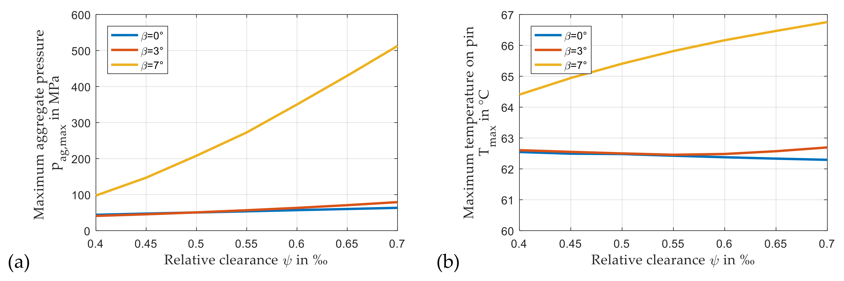
3.2. Impact of Radial Clearance on Load Carrying Capacity

Radial clearance is an important design parameter of hydrodynamic bearings. In particular, a suitable value of this parameter has to ensure two aspects. First, positive operating conditions for the entire nominal operating range of the bearing have to be guaranteed. Second, the bearing has to be robust against any disturbances from these conditions and tolerate shape deviations of the components due to the manufacturing process. Both aspects especially have to allow thermal changes of the radial clearance due to the transient operation of the machine.
Figure 11 exhibits the impact of the relative clearance on maximum pressure and temperature for different gear helix angles. While a comparably moderate influence of the relative clearance on maximum pressure exists for the lower helix angles of β = 0° and β = 3° in Figure 11a, a very significant change for the practical highly relevant helix angle β = 7° is observable as maximum pressure rises progressively with increasing relative clearance. Moreover, the maximum temperature on the pin sliding surface increases with rising relative clearance in Figure 11b for the maximum helix angle due to contact intensity, whereas a commonly expected decrease in this value is present for β = 0°. Generally, maximum temperature is only slightly higher than the nominal supply temperature, and consequently, thermal effects are not of major importance in this study. Results indicate that relative clearance should be designed as low as possible in the investigated range for β = 7°.

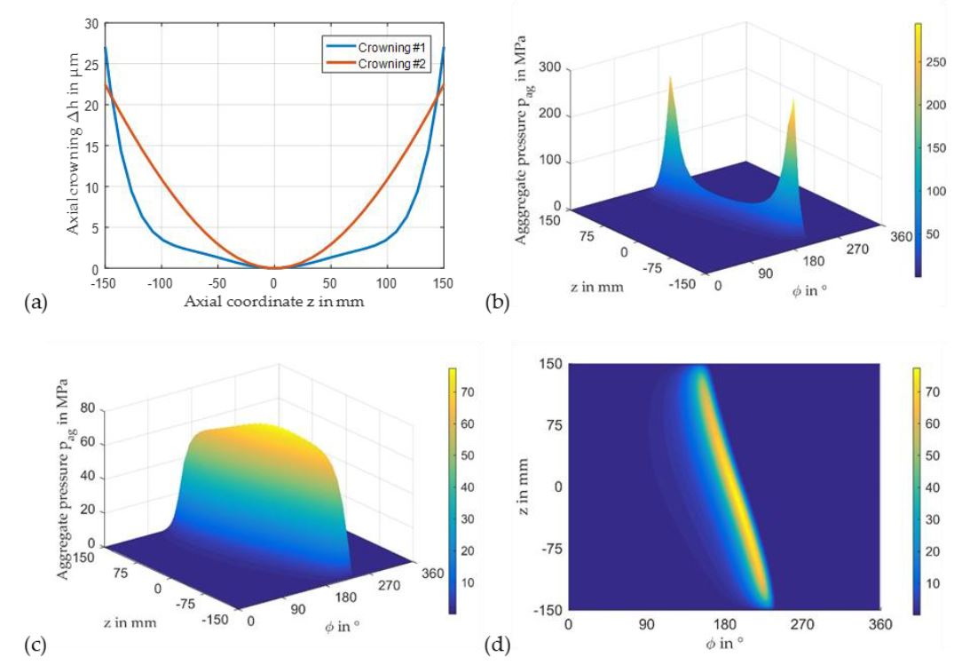
3.3. Impact of Axial Profiling

An axial crowning of contact partners with high edge loading is a common measure to reduce local maximum contact intensity. Examples for such applications are rolling element bearings or tooth flanks. To investigate the impact of axial crowning on the performance of the planet gear bearing, two different artificial crowning characteristics are defined according to Figure 12a and applied at nominal load conditions with a helix angle of β ≈ 7°. The first one focuses on profile relief at the bearing edges where maximum pressures occur, according to Figure 9b. The second one exhibits continuous parabolic shaped characteristic across the bearing width. Though the maximum pressure in Figure 12b slightly decreases compared to Figure 9b, the first profile tends to reduce the load-carrying bearing width. However, the second profile provokes a significant reduction of the pressure level. According to Figure 12c,d, a maximum pressure of 77.6 MPa is reached which is approximately 37% higher than the one for the straight tooth flanks in Figure 9a and acceptable for several bearing materials. Figure 12d illustrates the continuous pressure level in axial direction accompanying a homogenous load distribution in the bearing. The main cause for the advantages of the second crowning profile is that edge loading results from the tilting movement of the planet relative to the pin about the axis in load direction. Therefore, the crowning profile involves a comparably high region of nearly constant film thickness at nominal load that starts at ϕ ≈ 160° at z = 150 mm and ends at ϕ ≈ 235° at z = −150 mm, as depicted in Figure 13.

3.4. Operation at Part-Load and Over-Load Conditions

For the investigation of part-load and over-load conditions, the driving torque is varied, while planet speed remains constant. Assuming a homogenous load distribution in the gear mesh, the driving torque is proportional to the gear mesh forces causing the bearing load forces and moments. The subsequently presented figures include the relative input torque Tr. Figure 8 includes the corresponding force and moment loads.

3.4.1. Part-Load Conditions for Homogenous Load Distribution on Tooth Flank

In many applications, a geometrical optimization for nominal load conditions accompanies a degradation of the bearing performance in the part-load operating range. Figure 14 contrasts maximum pressure and minimum film thickness for the investigated planet gear bearing with crowning profile #2 and without crowning for relative loads ranging from Tr = 10% to 100%. Results clearly show that the crowning exhibits advantages in the entire investigated load range as maximum pressure decreases and minimum film thickness rises. Moreover, a strictly monotonous characteristic of these parameters can be observed, and operating conditions in the bearing become unfavorably with a rising relative load.

3.4.2. Part-Load and Over-Load Conditions for Constant Tooth Flank Geometry

While the previously presented results concordantly assume a homogenous load distribution on the gear mesh, this ideal case is now supplemented by the practical case of a certain tooth flank geometry designed for the nominal load case. The optimization of the tooth flank geometry generally aims to match the previously studied ideal case for the corresponding operating conditions. Consequently, only very low eccentricities of the tangential and radial gear mesh forces to the middle plane of the bearing exist at nominal load conditions. This shape optimization accompanies the eccentricities of these forces for all other load cases. With increasing load, the resulting mesh forces move along the tooth flank from one side of the planet to the other one and across the center plane for the nominal load case. Therefore, a load-dependent derivation of the moments from the ideal case is present and depicted for an artificial tooth flank geometry in Figure 15. According to Figure 15a, a parabolic shape of the characteristic of moment My is assumed between relative loads Tr = 0 and 100%, and a linear one is present in the overload range. The moment Mx in Figure 15b remains unchanged as no shifts are considered between the meshing points of sun and planet gear and planet and ring gear, respectively. In opposite to the ideal case studied so far, the direction of the resulting moment load varies with driving torque. Figure 15c shows a rise of the resulting moment load due to the eccentricity of the tangential mesh forces depicted in Figure 15d. In particular, the moment loads in the part-load region are much higher, as the yellow curve in Figure 15c illustrates.
The modified bearing loads are applied to the bearing with crowning #2 and cause a significant modification of the characteristics previously shown in Figure 14. Figure 16 indicates a degradation of the characteristic parameters, in particular, in the part-load range. While the mesh forces, and therefore, the bearing force loads are identical for the practical and ideal case, their application point changes, and the bearing moment load rises. Consequently, the minimum film thickness for the practical case in Figure 16b decreases and is partly below the value predicted for the nominal load case. Moreover, monotonous characteristics of maximum pressure and minimum film thickness do not exist anymore.

3.5. Modification of the Lubricant Gap by Wear

According to the previous results, load conditions of planet gear bearings might incorporate operation in the mixed friction regime. Consequently, wear mechanisms can arise. To study their general impact on the conditions in the contact between planet and pin, solid contact forces Fsol are used to evaluate wear according to Archard’s law [27].
V w = k H · F s o l · L = K · F s o l · L
The wear volume Vw is a function of the contact force Fsol, the sliding distance L and the wear coefficient K. It is assumed that the softer material is located on the stator side provoking a two-dimensional variable distribution of wear on the sliding surface of the bearing without axial crowning. In the concrete case, a wear coefficient of K = 8.5 · 10 9   m m 3 / J and an operation time of t = 280 h at nominal load is assumed. These operating conditions cause significant wear according to Figure 17a. Figure 17b shows the characteristic of the maximum aggregate pressure and minimum film thickness during the run. Here, wear increases minimum film thicknesses and decreases maximum pressure monotonously in the first 160 h. After 160 h a nearly constant level of minimum film thickness close to pure hydrodynamic operation is reached that slightly reduces in the further run. The pressure level decreases monotonously throughout the entire investigated time range. Local maximum pressures tend to shift to the middle plane similar to the behavior observed in the results for crowning #1 in Figure 12b. Nevertheless, maximum pressures significantly reduce as wear accompanies regions of only slightly changed film thickness. To show this phenomenon more clearly, the run time is extended to 560 h. Figure 18b depicts an extension of the load-carrying region in the circumferential direction of the bearing due to wear. Therefore, maximum pressure reaches a level comparable to the one predicted for the unworn bearing with crowning #2 in Figure 12d. Though the pressure is more homogenous in the axial direction with the crowning, Figure 18a indicates that the load-carrying region in the circumferential direction, which is enclosed by the two red lines in both partial figures, is smaller than the one of the worn bearing.

4. Discussion and Conclusions

This paper focuses on specific operating conditions of sliding planet gear bearings for wind turbine gearbox applications as well as on the impact of particular design parameters on the properties in the contact between pin and planet. Special emphasis is given to the influence of the helix angle of the gear. A helix angle greater than zero incorporates additional moment loads that have to be restored by the bearing and accompany the edge loading phenomena and mixed friction processes in the lubricant film.
The level of edge loading is very sensitive to relative bearing clearance for higher helix angles. Results of a variation of relative clearance in a practical relevant range indicate an improvement of the load-carrying capacity with a reduction of this parameter. However, for practical applications, sufficiently high clearances are required that prevent problems during transient operation or undesirable influences of manufacturing tolerances. Moreover, the system has to be robust to sustain the deformation of its flexible components due to the high mechanical loads. As a second geometrical design parameter, axial crowning of the sliding surface is an appropriate measure to reduce maximum contact pressures. Contrary to the straight cylindrical pin and planet bore geometry, a homogenization of the contact pressure on the oblique line of maximum load exists. The shape of the crowning has to approach the contact surfaces of planet and pin in this region to reduce high deviations of the film thickness that exists due to misalignment between the contact partners.
Results for part-load conditions reveal critical characteristic operating parameters if the load-carrying behavior of the gear mesh contact is considered. In particular, the minimum film thickness is of the magnitude as at nominal operation or can be even lower. Though the intensity of mixed friction might be lower due to the lower mechanical load, issues may arise over the lifetime of the machine. Consequently, distinct characterizations of tooth flank geometry as well as part-load conditions have to be the input parameters of the bearing design process. Moreover, neglecting the additional load moments caused by the eccentricity of tangential forces in the gear mesh contact might lead to a completely different result assessment.
Wear processes in the bearing are able to adapt the shape of the lubricant gap to the specific requirements of the bearing at operation. While load-carrying capacity is improved by wear in the investigated case, the characteristic of the gap deviates from the one determined, applying a crowning to the bearing because wear particularly arises on the bearing edges. Therefore, the worn gap profile represents an improvement but not an optimization of the bearing geometry. If the occurrence of wear is tolerable by the tribologic system, it might be a measure to adjust the bearing itself to the operating conditions, involving leaving out manufacturing steps for the axial crowning. However, this option must be carefully evaluated because the danger of bearing damage arises if the intensity of the wear becomes too high.
According to these investigations, the design process of planet gear bearings for wind turbine applications involves several specific aspects that need to be studied in detail to meet the high requirements on the reliability of wind turbine applications. Additionally, the impact of deformation of the comparably flexible planet stage structure on the operating behavior of the bearing needs to be considered according to part 2 of these investigations [27]. Furthermore, future studies must provide details on the validation of these results.

Author Contributions

Conceptualization, methodology, T.H., H.D., E.R.; software, T.H.; investigation, writing, and visualization, T.H., H.D., E.R.; supervision and funding acquisition, H.S. All authors have read and agreed to the published version of the manuscript.

Funding

This research was funded by the German Federal Ministry of Economic Affairs and Energy. The financial support was assigned by the Industrial Research Association (AiF e. V.) in project number IGF 19425 N/1.

Acknowledgments

The authors thank the expert committees of the German research community FVA e. V. for the technical and scientific steering of this research project.

Conflicts of Interest

The authors declare no conflict of interest.

Nomenclature

clubricant specific heat
CRradial clearance
d1pitch diameter
eEccentricity between pin and planet
F0, F1, F2viscosity factors
Fforce
hfilm thickness
Mmoment
nrotor speed
ppressure
Rqroot mean square surface roughness
Ttemperature, torque
Usurface speed
u, v, wflow velocities
x, y, zCartesian coordinates
X,Ytranslational displacement relative to equilibrium position
Θlubricant density ratio
γattitude angle
ηlubricant dynamic viscosity
λlubricant conductivity
ρlubricant density
φx, φyalignment angle about x-,y-axis
φX, φYalignment angle about x-,y-axis relative to equilibrium position
ϕangular coordinate
ϕxzppressure flow factors
ΦxSshear flow factor

References

  1. Ragheb, A.; Ragheb, M. Wind turbine gearbox technologies. In Proceedings of the 2010 1st International Nuclear & Renewable Energy Conference (INREC), Amman, Jordan, 21–24 March 2010; pp. 1–8. [Google Scholar]
  2. Tavner, P.J.; Xiang, J.; Spinato, F. Reliability analysis for wind turbines. Wind Energy 2007, 10, 1–18. [Google Scholar] [CrossRef]
  3. Ribrant, J.; Bertling, L. Survey of failures in wind power systems with focus on Swedish wind power plants during 1997–2005. In Proceedings of the 2007 IEEE Power Engineering Society General Meeting, Tampa, FL, USA, 24–28 June 2007; pp. 1–8. [Google Scholar]
  4. Qiao, W.; Lu, D. A survey on wind turbine condition monitoring and fault diagnosis—Part I: Components and subsystems. IEEE Trans. Ind. Electron. 2015, 62, 6536–6545. [Google Scholar] [CrossRef]
  5. Jones, A.; Harris, T.A. Analysis of a Rolling-Element Idler Gear Bearing Having a Deformable Outer-Race Structure. J. Basic Eng. 1963, 85, 273–278. [Google Scholar] [CrossRef]
  6. Fingerle, A.; Hochrein, J.; Otto, M.; Stahl, K. Theoretical Study on the Influence of Planet Gear Rim Thickness and Bearing Clearance on Calculated Bearing Life. J. Mech. Des. 2019, 142, 031102. [Google Scholar] [CrossRef]
  7. Bouyer, J.; Fillon, M. An Experimental Analysis of Misalignment Effects on Hydrodynamic Plain Journal Bearing Performances. J. Tribol. 2001, 124, 313–319. [Google Scholar] [CrossRef]
  8. Sun, J.; Changlin, G. Hydrodynamic lubrication analysis of journal bearing considering misalignment caused by shaft deformation. Tribol. Int. 2004, 37, 841–848. [Google Scholar] [CrossRef]
  9. Hili, M.A.; Bouaziz, S.; Maatar, M.; Fakhfakh, T.; Haddar, M. Hydrodynamic and Elastohydrodynamic Studies of a Cylindrical Journal Bearing. J. Hydrodyn. 2010, 22, 155–163. [Google Scholar] [CrossRef]
  10. Hagemann, T.; Kukla, S.; Schwarze, H. Measurement and prediction of the static operating conditions of a large turbine tilting-pad bearing under high circumferential speeds and heavy loads. In Proceedings of the ASME Turbo Expo 2013, San Antonio, TX, USA, 3–7 June 2013. [Google Scholar]
  11. Prölß, M. Berechnung Langsam Laufender und Hoch Belasteter Gleitlager in Planetengetrieben unter Mischreibung, Verschleiß und Deformationen. Ph.D. Thesis, Clausthal University of Technology, Clausthal-Zellerfeld, Germany, 2020. [Google Scholar]
  12. Hagemann, T.; Schwarze, H. A Model for Oil Flow and Fluid Temperature Inlet Mixing in Hydrodynamic Journal Bearings. J. Tribol. 2018, 141, 021701. [Google Scholar] [CrossRef]
  13. Muzakkir, S.M.; Hirani, H.; Thakre, G.D. Lubricant for Heavily Loaded Slow-Speed Journal Bearing. Tribol. Trans. 2013, 56, 1060–1068. [Google Scholar] [CrossRef]
  14. Linjamaa, A.; Lehtovaara, A.; Larsson, R.; Kallio, M.; Söchting, S. Modelling and analysis of elastic and thermal deformations of a hybrid journal bearing. Tribol. Int. 2018, 118, 451–457. [Google Scholar] [CrossRef]
  15. Xiang, G.; Han, Y.; Wang, J.; Wang, J.; Ni, X. Coupling transient mixed lubrication and wear for journal bearing modeling. Tribol. Int. 2019, 138, 1–15. [Google Scholar] [CrossRef]
  16. Garabedian, N.T.; Gould, B.J.; Doll, G.L.; Burris, D.L. The Cause of Premature Wind Turbine Bearing Failures: Overloading or Underloading? Tribol. Trans. 2018, 61, 850–860. [Google Scholar] [CrossRef]
  17. Hagemann, T.; Ding, H.; Radtke, E.; Schwarze, H. Operating behavior of sliding planet gear bearings in wind turbine gearbox applications—Part II: Impact of structure deformation. Lubricants 2021, in press. [Google Scholar]
  18. Patir, N.; Cheng, H.S. An Average Flow Model for Determining Effects of Three-Dimensional Roughness on Partial Hydrodynamic Lubrication. J. Lubr. Technol. 1978, 100, 12–17. [Google Scholar] [CrossRef]
  19. Falz, E. Grundzüge der Schmierungstechnik; Springer: Berlin/Heidelberg, Germany, 1931. [Google Scholar]
  20. Elrod, H.G. A Cavitation Algorithm. J. Lubr. Technol. 1981, 103, 350–354. [Google Scholar] [CrossRef]
  21. Patankar, S.V. Numerical Heat Transfer and Fluid Flow; CRC Press: Boca Raton, FL, USA, 1980; ISBN 9781315275130. [Google Scholar]
  22. Waltermann, H. Optimierte Thermo-Elasto-Hydrodynamische Berechnungsverfahren für Gleitlager. Ph.D. Thesis, Rheinisch-Westfälisch Technische Hochschule Aachen, Aachen, Germany, 1992. [Google Scholar]
  23. Hagemann, T.; Zemella, P.; Pfau, B.; Schwarze, H. Experimental and theoretical investigations on transition of lubrication conditions for a five-pad tilting-pad journal bearing with eccentric pivot up to highest surface speeds. Tribol. Int. 2020, 142, 106008. [Google Scholar] [CrossRef]
  24. Greenwood, J.A.; Tripp, J.H. The Contact of Two Nominally Flat Rough Surfaces. Proc. Inst. Mech. Eng. 1970, 185, 625–633. [Google Scholar] [CrossRef]
  25. Prölß, M.; Schwarze, H.; Hagemann, T.; Zemella, P.; Winking, P. Theoretical and Experimental Investigations on Transient Run-Up Procedures of Journal Bearings Including Mixed Friction Conditions. Lubricants 2018, 6, 105. [Google Scholar] [CrossRef] [Green Version]
  26. Hu, Y.; Cheng, H.S.; Arai, T.; Kobayashi, Y.; Aoyama, S. Numerical Simulation of Piston Ring in Mixed Lubrication—A Nonaxisymmetrical Analysis. J. Tribol. 1994, 116, 470–478. [Google Scholar] [CrossRef]
  27. Archard, J.F. Contact and Rubbing of Flat Surfaces. J. Appl. Phys. 1953, 24, 981–988. [Google Scholar] [CrossRef]
Figure 1. Basic design and kinematic properties of a planet stage for a wind turbine gearbox.
Lubricants 09 00097 g001
Figure 2. Mesh forces and bearing load for (a) straight gear, (b) helical gear, and (c) the helical gear assembled in the planet stage.
Lubricants 09 00097 g002
Figure 3. Numerical grid for temperature evaluation for the (a) journal bearing and (b) planet gear bearing.
Lubricants 09 00097 g003
Figure 4. Cross section of the three-dimensional solution domain of the temperature analysis (a) journal bearing, and (b) planet gear bearing at a certain axial position.
Lubricants 09 00097 g004
Figure 5. Pressure distributions determined by Sun and Changlin [8] (a,c) and the planet gear bearing code (b,d) for misalignment angles of γ = 0.0° (a,b) and γ = 0.03° (c,d).
Lubricants 09 00097 g005
Figure 6. Resulting moment for different levels of misalignment angles determined by Sun and Changlin [8] (a) and the planet gear bearing code (b).
Lubricants 09 00097 g006
Figure 7. Pressure and shear flow factors (a) and solid body contact pressure (b).
Lubricants 09 00097 g007
Figure 8. Force (a) and moment load (b) due to relative mesh load.
Lubricants 09 00097 g008
Figure 9. Pressure distributions @ nominal operating conditions (a) straight gear (β = 0°) and (b) helical gear (β = 7°) (npl = 30 rpm, Fsc = 900 kN, Tsup = 60 °C, psup = 0.2 MPa, Msc = 27.6 kNm (b)).
Lubricants 09 00097 g009
Figure 10. Impact of helix angle of helical gear on (a) maximum pressures, minimum film thickness, and (b) alignment angles between planet and pin (npl = 30 rpm, Fsc = 900 kN, Tsup = 60 °C, psup = 0.2 MPa).
Lubricants 09 00097 g010
Figure 11. Maximum pressure (a) and maximum temperature on the pin sliding surface (b) for variable relative loads (npl = 30 rpm, Fsc = 900 kN, Tsup = 60 °C, psup = 0.2 MPa).
Lubricants 09 00097 g011
Figure 12. Impact of axial crowning (a) on the pressure distribution: (b) crowning #1, (c,d) crowning #2 (npl = 30 rpm, Fsc = 900 kN, Tsup = 60 °C, psup = 0.2 MPa, β = 7°, Msc = 27.6 kNm).
Lubricants 09 00097 g012
Figure 13. Film thickness @ nominal operating conditions with crowning #2 (npl = 30 rpm, Fsc = 900 kN, Tsup = 60 °C, psup = 0.2 MPa, β = 7°, Msc = 27.6 kNm).
Lubricants 09 00097 g013
Figure 14. Maximum pressure (a) and minimum film thickness (b) for variable relative loads (npl = 30 rpm, Tsup = 60 °C, psup = 0.2 MPa, β = 7°).
Lubricants 09 00097 g014
Figure 15. Load moments My (a), Mx (b), and Mres (c) for variable relative loads (npl = 30 rpm, Tsup = 60 °C, psup = 0.2 MPa, β = 7°); eccentricity of tangential mesh force from the middle plane (d).
Lubricants 09 00097 g015
Figure 16. Maximum aggregate pressure (a) and minimum film thickness (b) for variable relative loads (npl = 30 rpm, Tsup = 60 °C, psup = 0.2 MPa, β = 7°).
Lubricants 09 00097 g016
Figure 17. Wear after 280 h run (a), maximum aggregate pressure and minimum film thickness (b), and pressure distribution after 280 h run (c,d) (npl = 30 rpm, Tsup = 60 °C, psup = 0.2 MPa, β = 7°, t = 280 h).
Lubricants 09 00097 g017
Figure 18. Comparison of pressure distribution with crowning #2 (a) and without crowning after 560 h (b) (npl = 30 rpm, Tsup = 60 °C, psup = 0.2 MPa, β = 7°).
Lubricants 09 00097 g018
Table 1. Bearing parameters [8].
ParameterValue
Geometrical properties
Number of pads, -1
Nominal diameter, mm60
Bearing width, mm66
Radial clearance, µm30
Pad sliding surface preload, -0.0
Static analysis parameters
Rotational speed, rpm3000
Lubricant properties
Lubricant dynamic viscosity, mPas9.0
Table 2. Planet gear bearing parameters.
ParameterValue
Geometrical properties
Number of pads, -1
Nominal diameter, mm250
Pitch circle diameter, mm499
Bearing width, mm300
Angular span of lube oil pocket, degrees20.5
Width of lube oil pocket, mm260
Radial clearance, µm138
Pad sliding surface preload, -0.0
Static analysis parameters
Nominal rotational speed, rpm30
Nominal bearing load, kN900
Lubricant supply temperature, °C60
Lube oil supply pressure, MPa0.2
Lubricant properties
LubricantISO VG 320
Lubricant density kg/m3865 @ 40 °C
Lubricant specific heat capacity kJ/(kg·K)2.0 @ 20 °C
Lubricant thermal conductivity, W/(m·K)0.13
Publisher’s Note: MDPI stays neutral with regard to jurisdictional claims in published maps and institutional affiliations.

