Deformation Behavior Causing Excessive Thinning of Outer Diameter of Micro Metal Tubes in Hollow Sinking

 and
and
Abstract
:1. Introduction
2. Materials and Methods
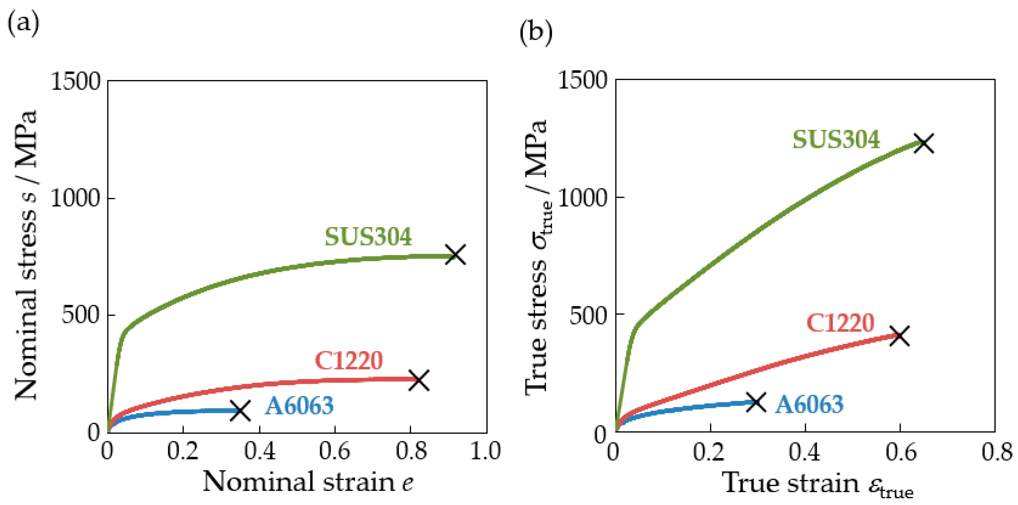
2.1. Materials
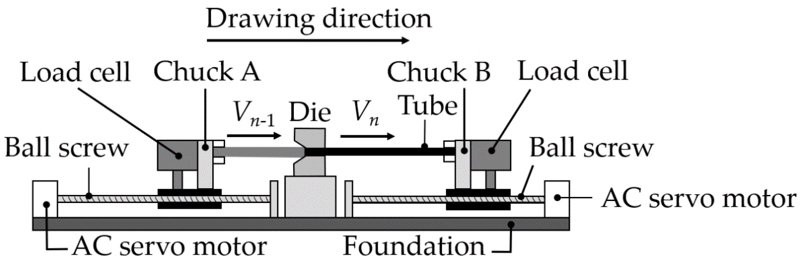
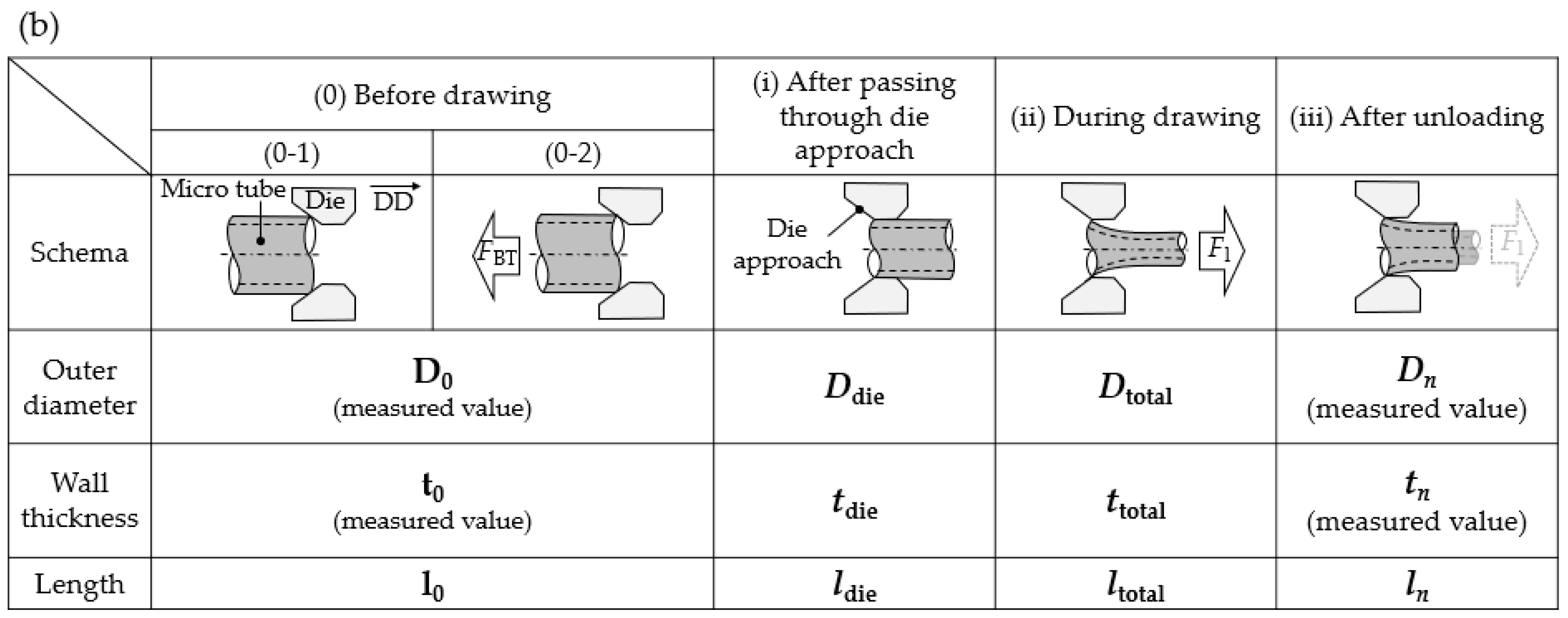
2.2. Hollow Sinking
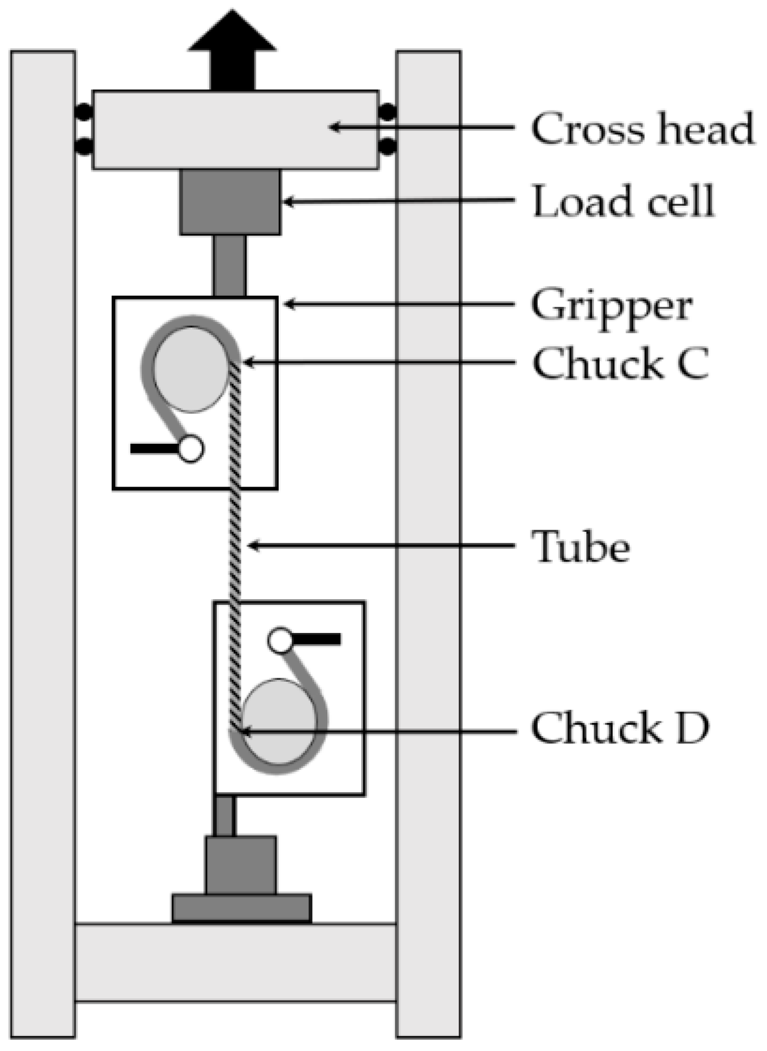
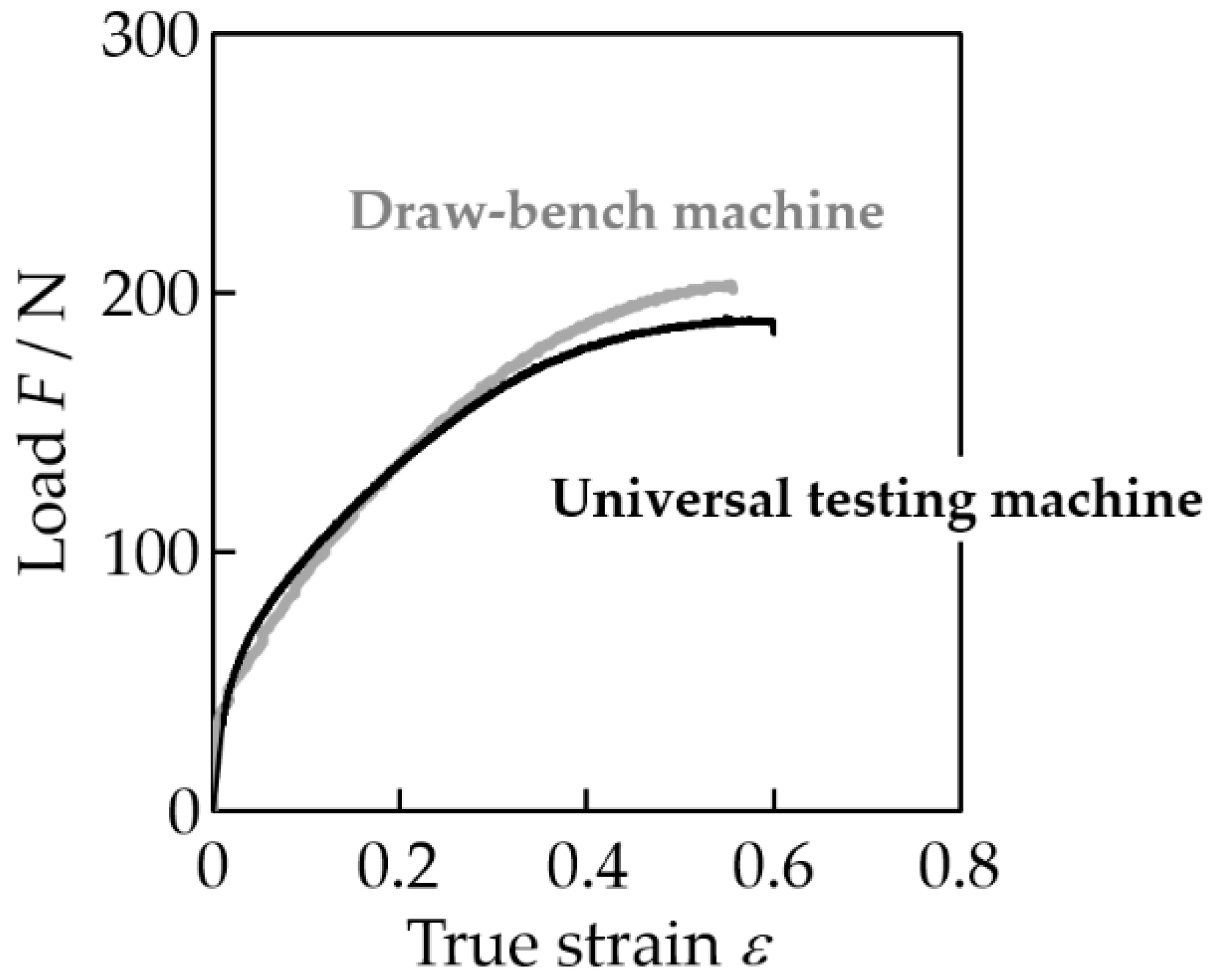
2.3. Tensile Test
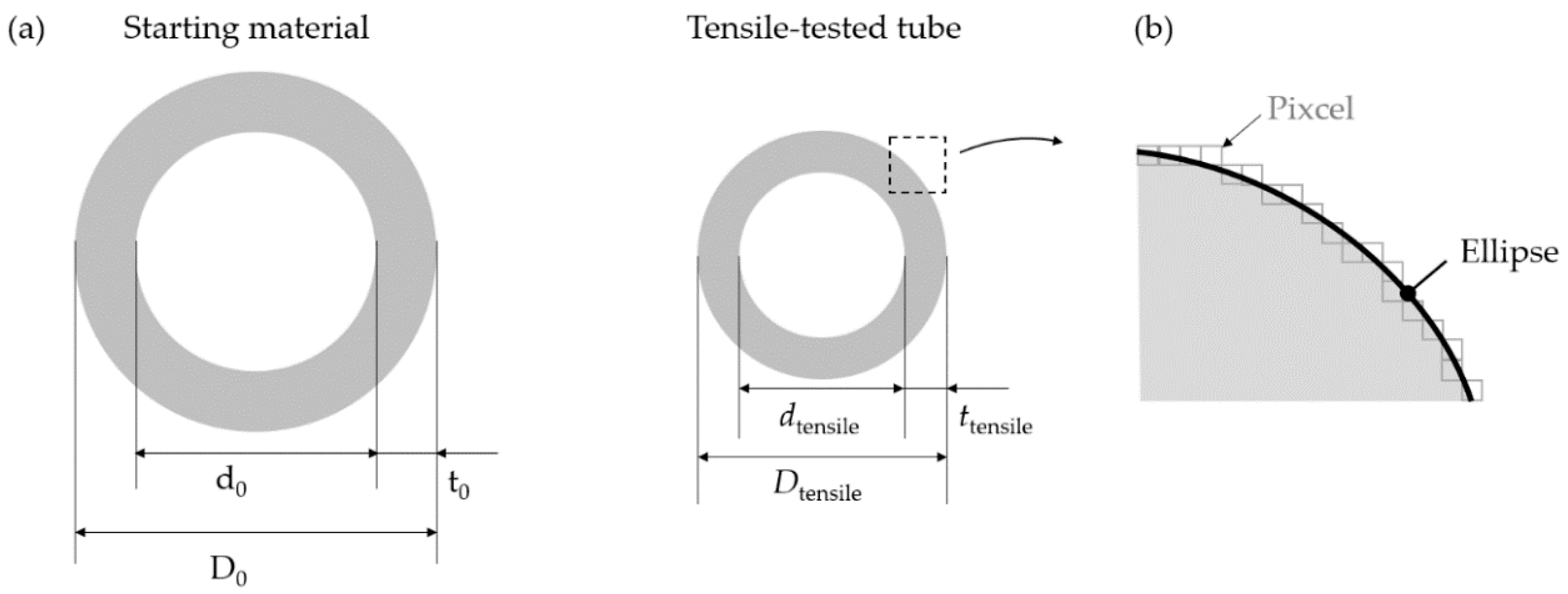
2.4. Dimension and Surface Quality Measurement
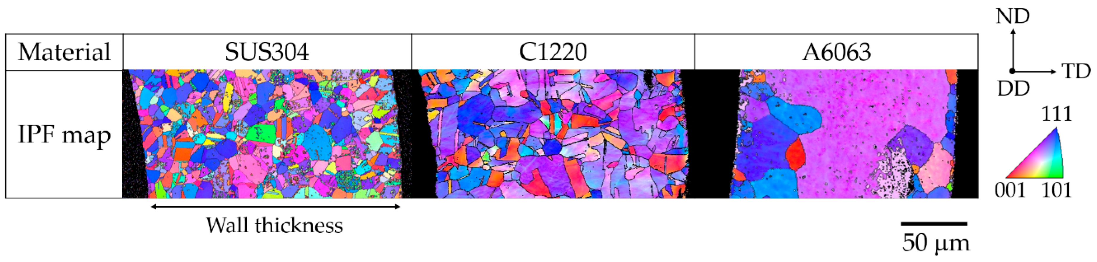
2.5. Microstructural Observation
3. Results
3.1. Grain Number across Wall Thicknesses of Staring Materials
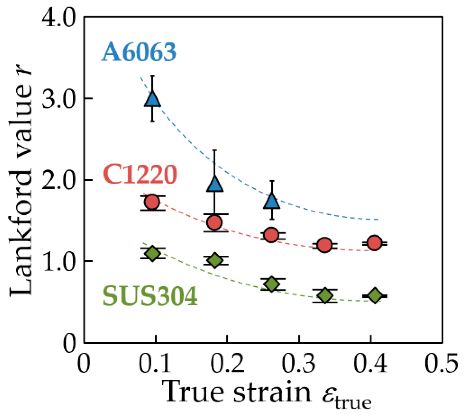
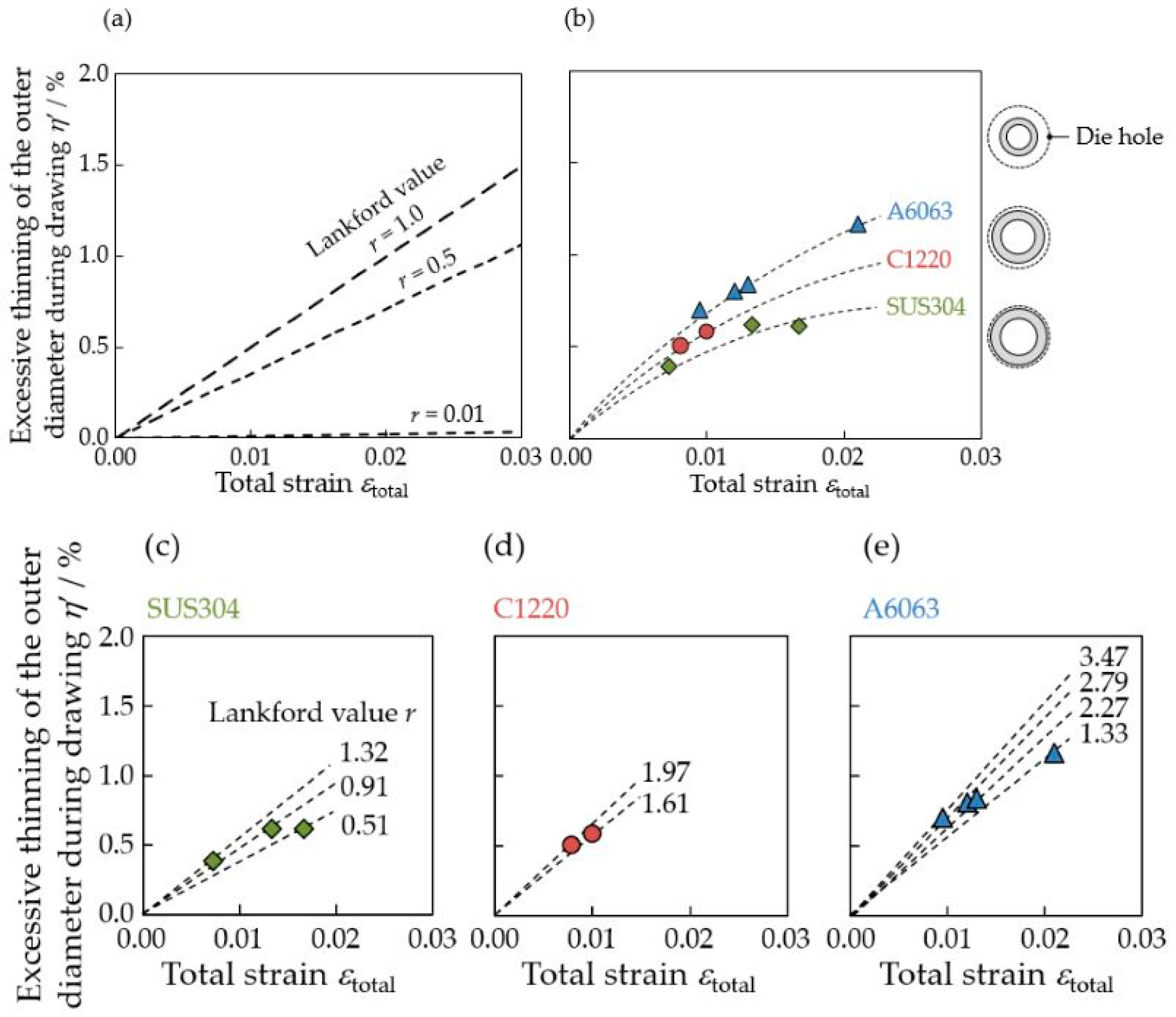
3.2. Lankford Value of Starting Materials
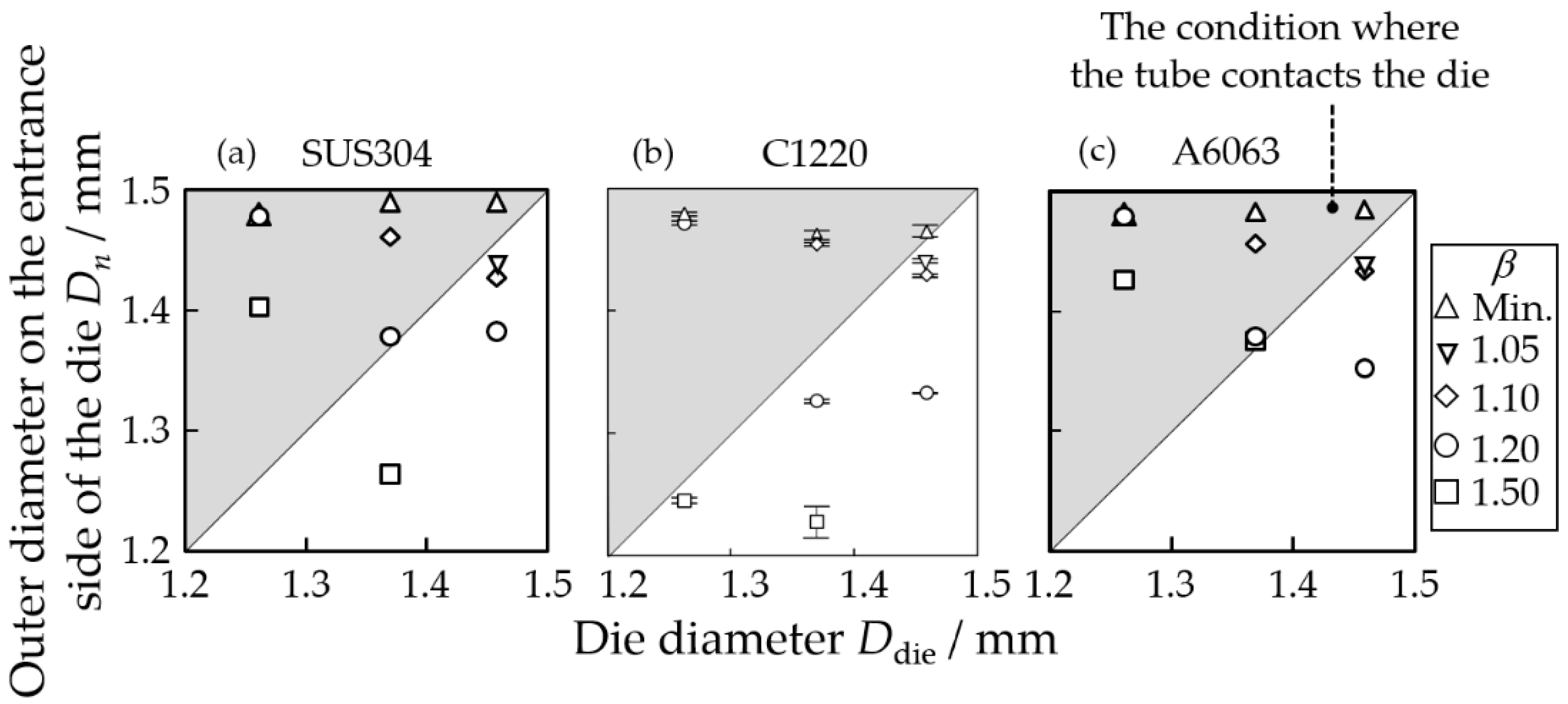
3.3. Dimension of Drawn Tubes
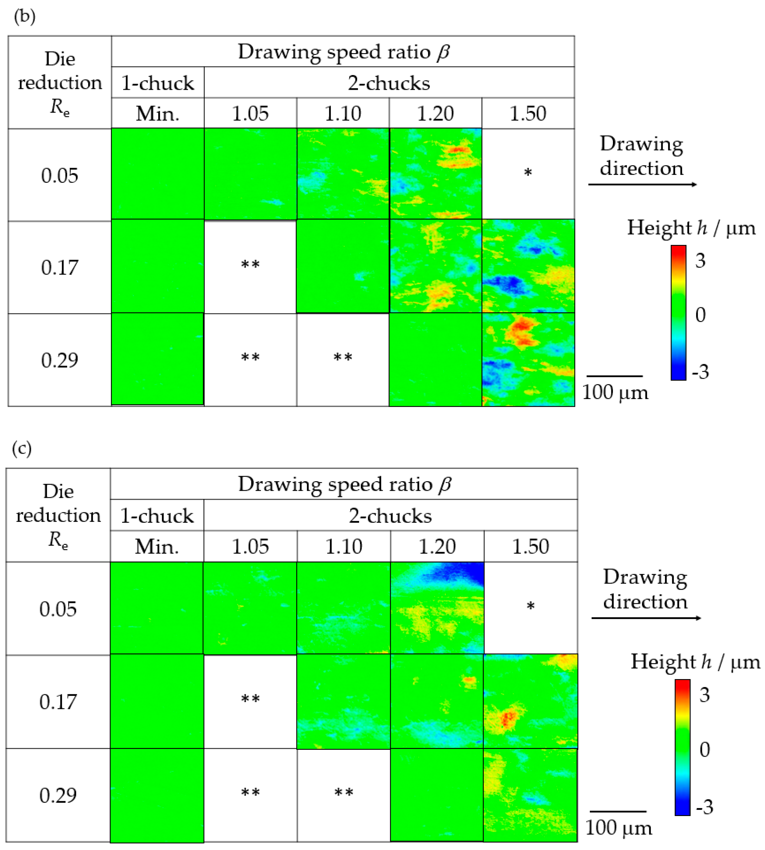
3.4. Outer Surface Quality of Drawn Tubes
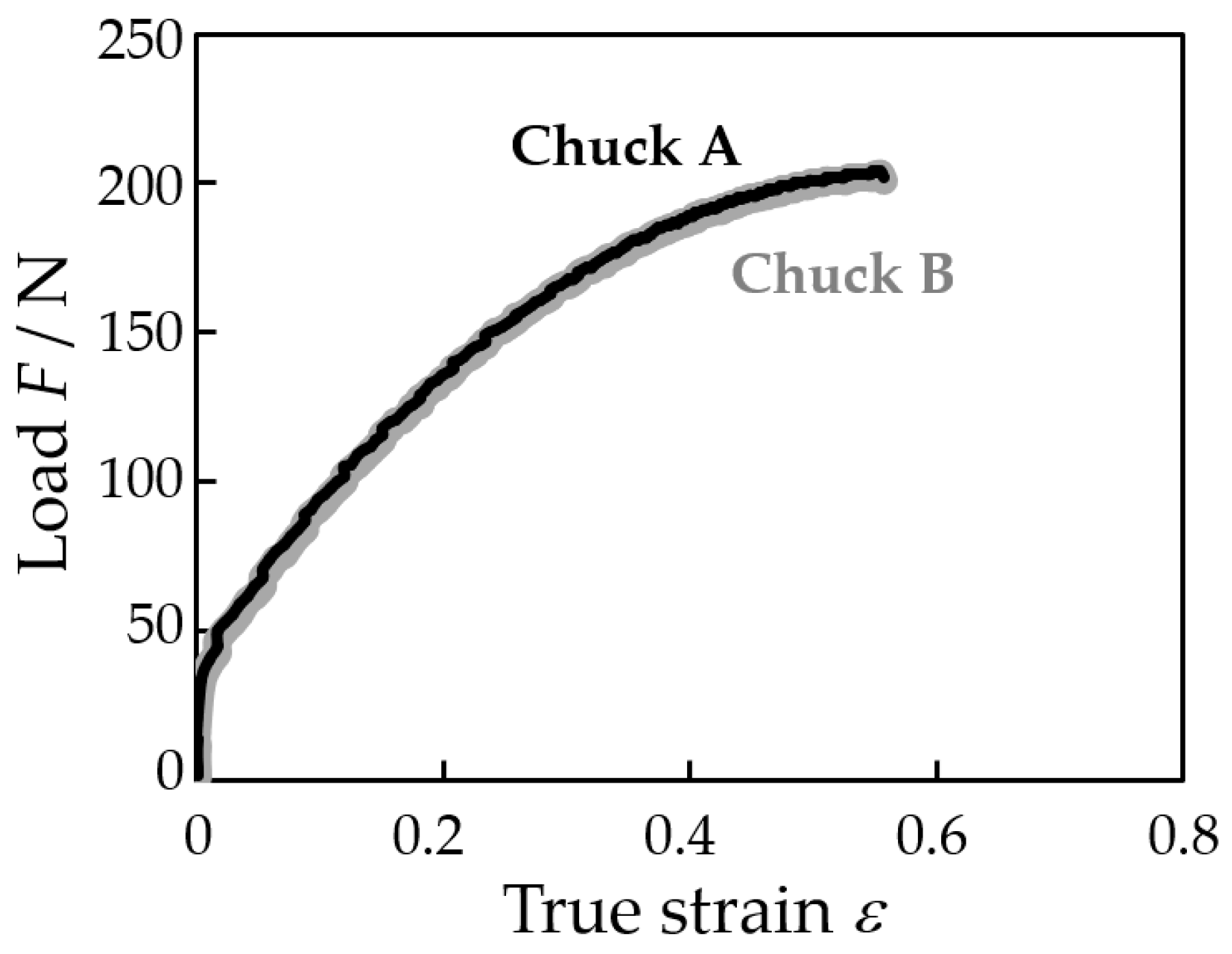
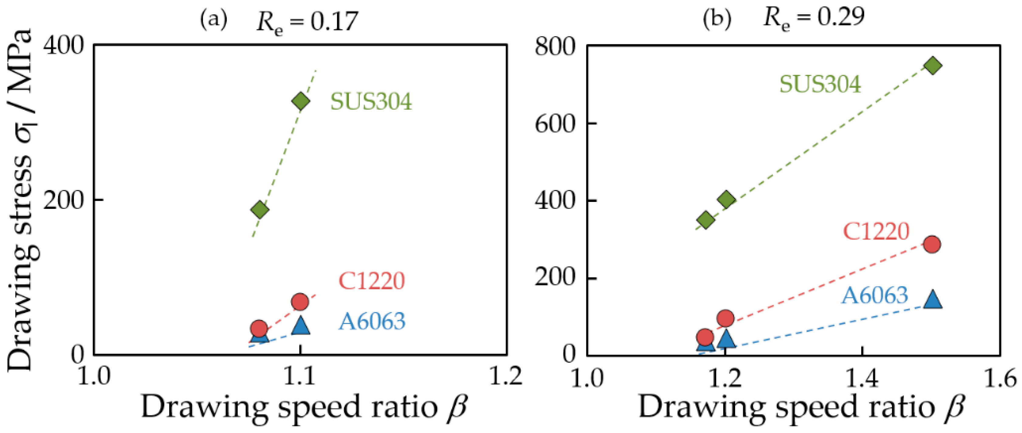
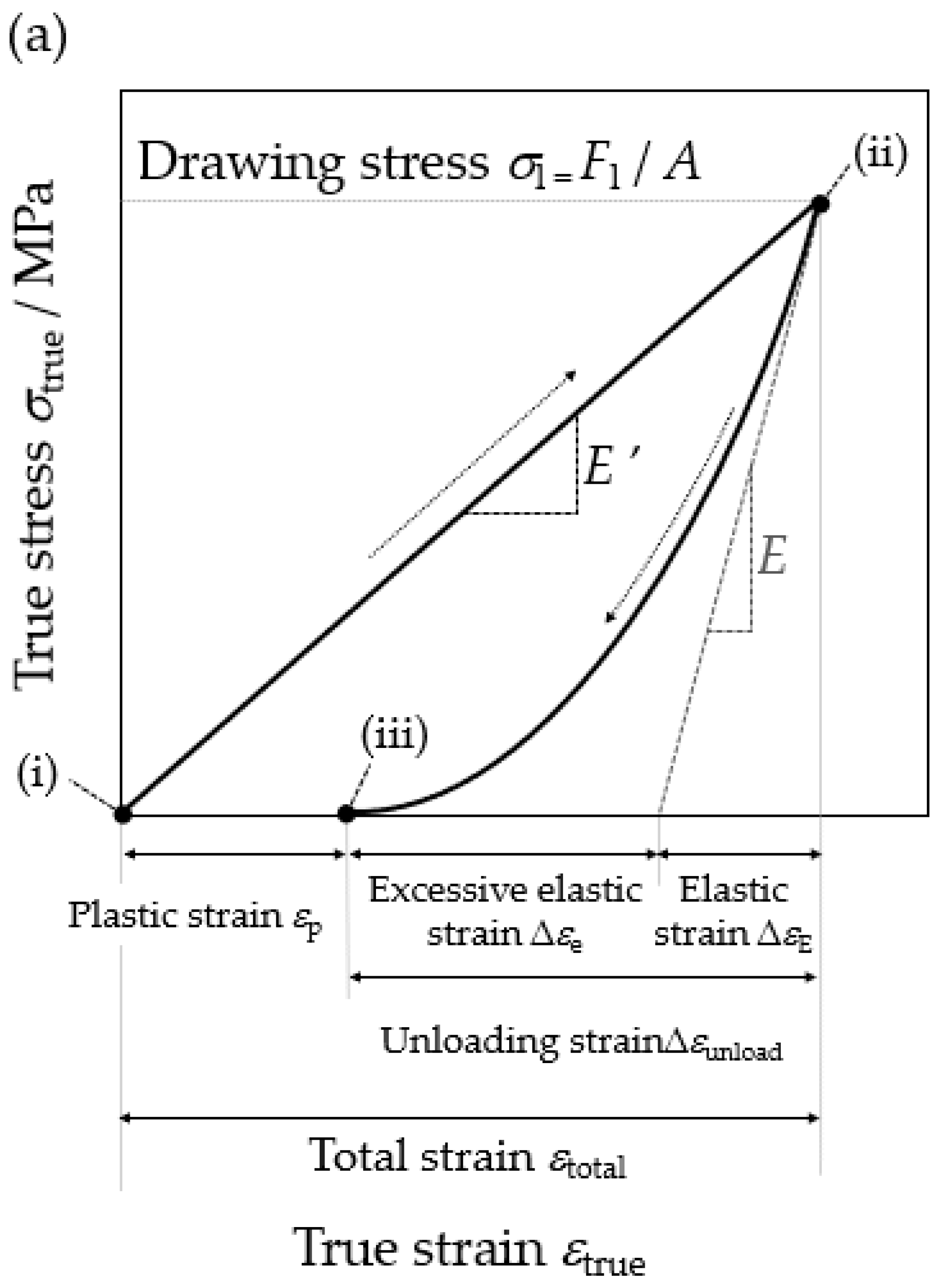
3.5. Drawing Stress during Drawing
4. Discussion
4.1. Conditions to Prevent Non Contact between the Tube and Die
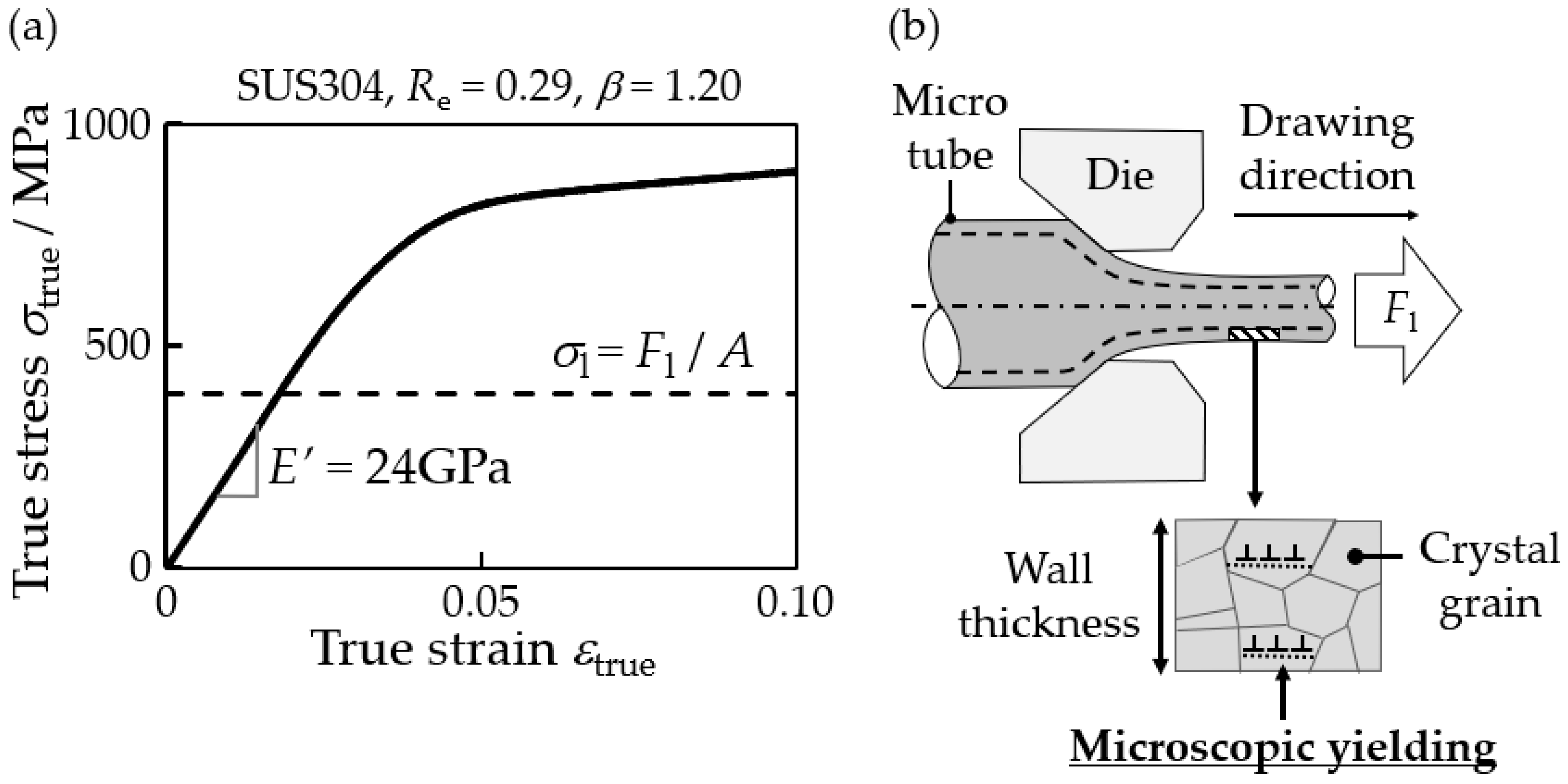
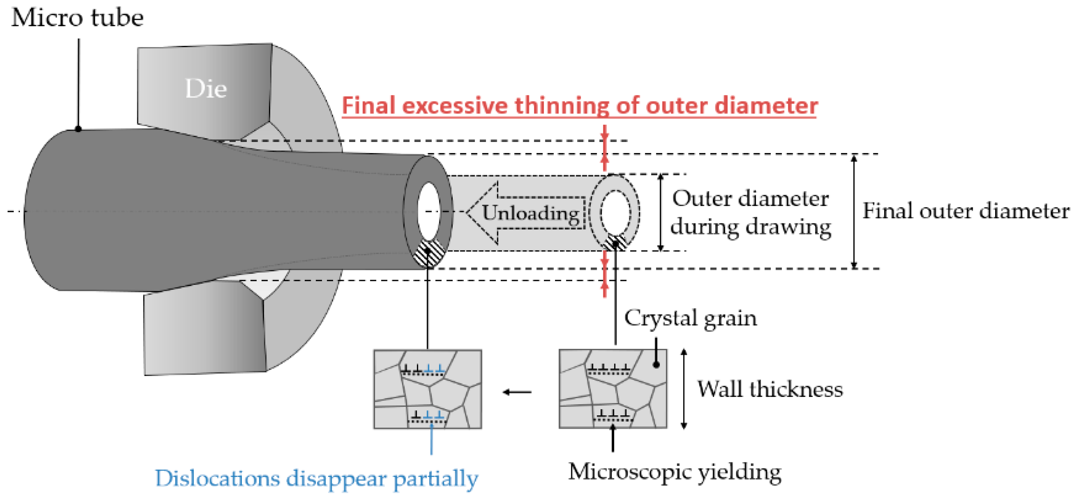
4.2. Mechanism of the Excessive Thinning of the Outer Diameter during and after Drawing
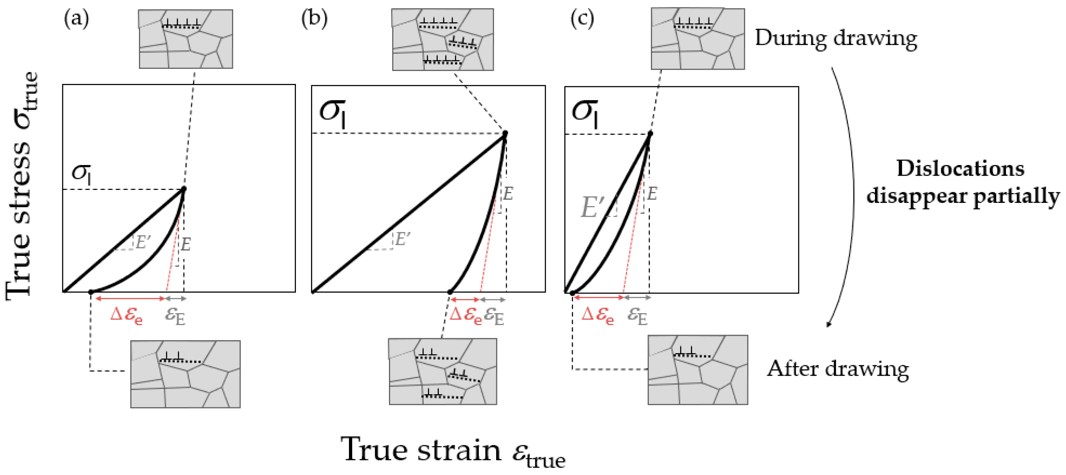
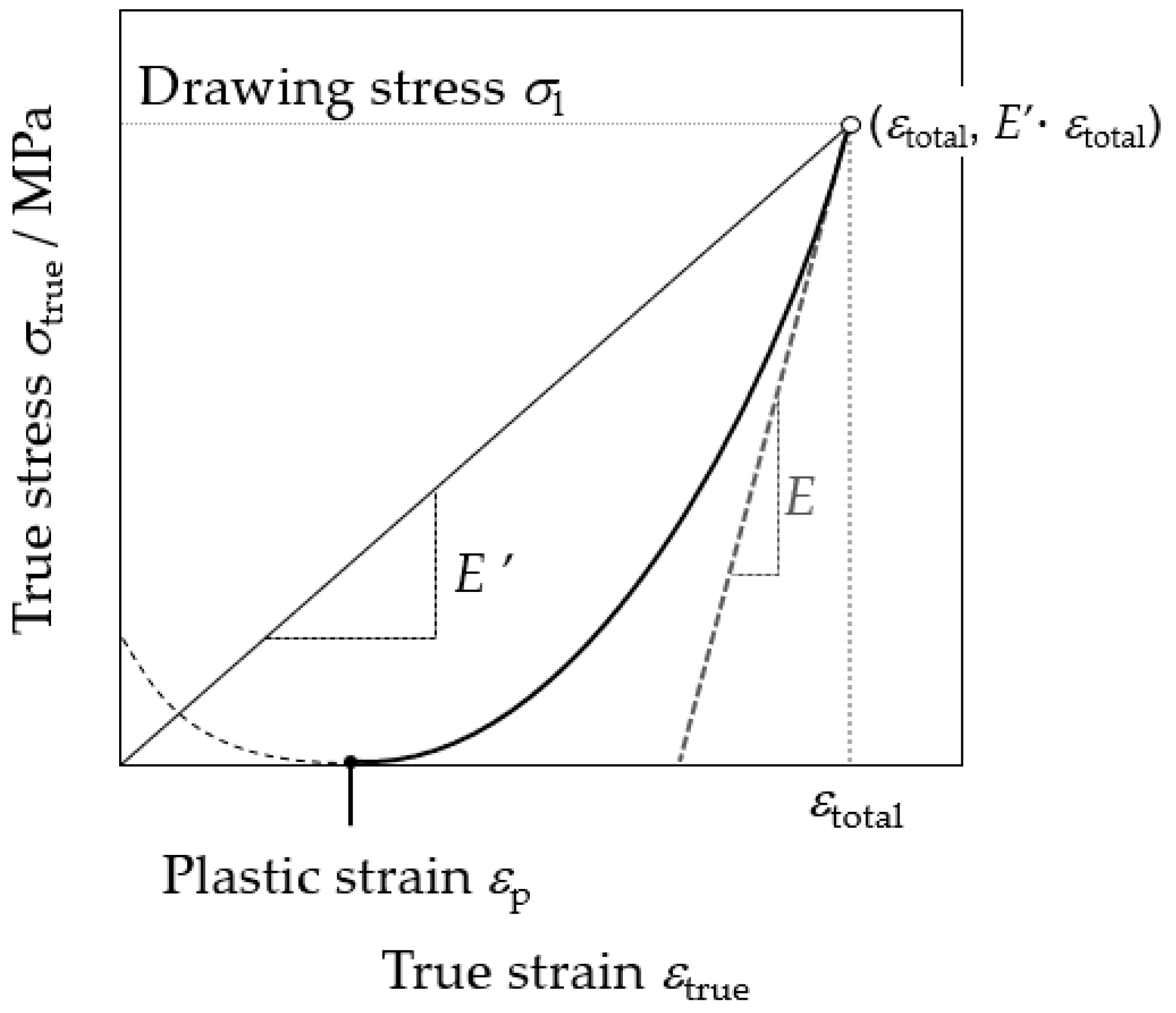
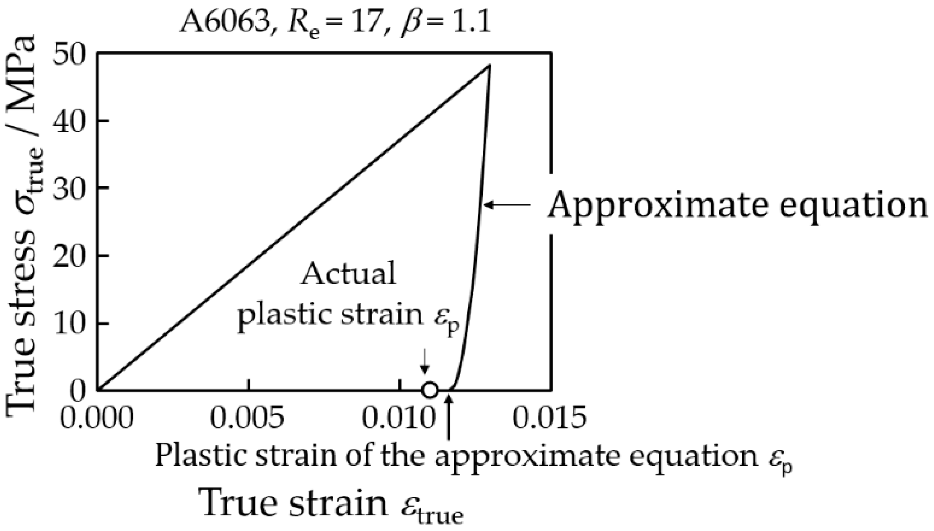
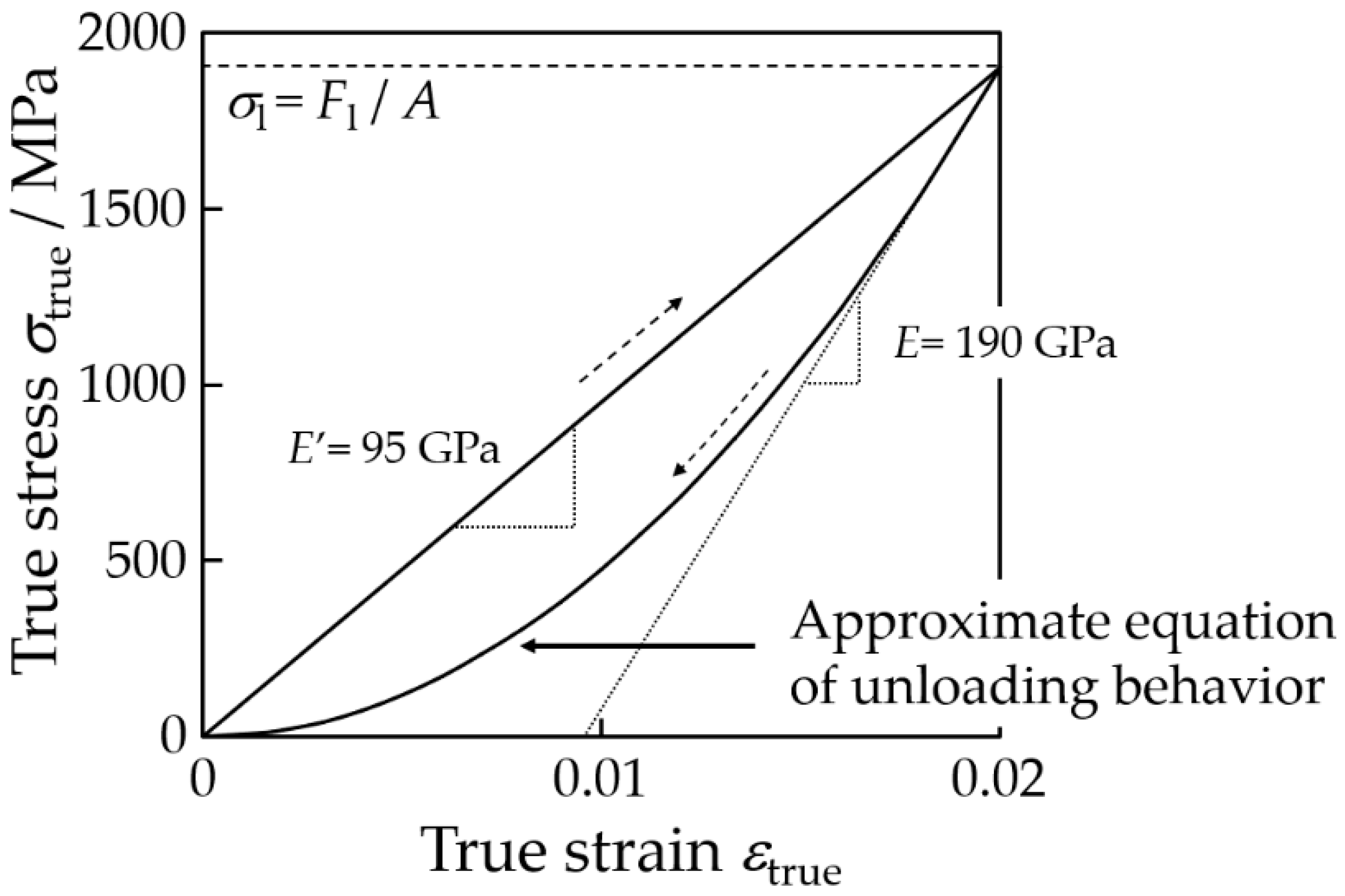
4.2.1. Deformation Behavior of Micro Tube during Drawing and Unloading
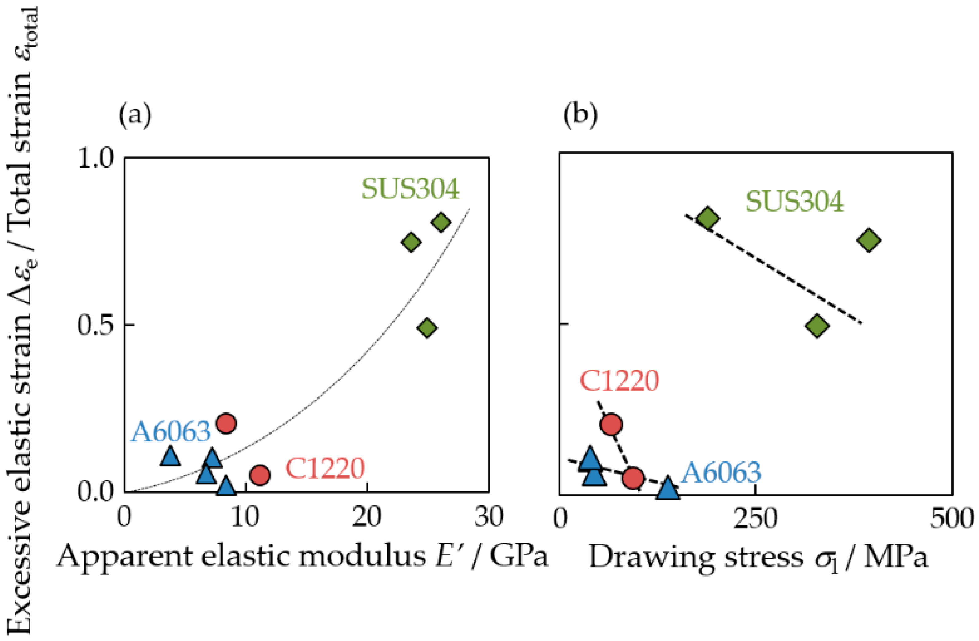
4.2.2. Excessive Thinning of the Outer Diameter during Drawing
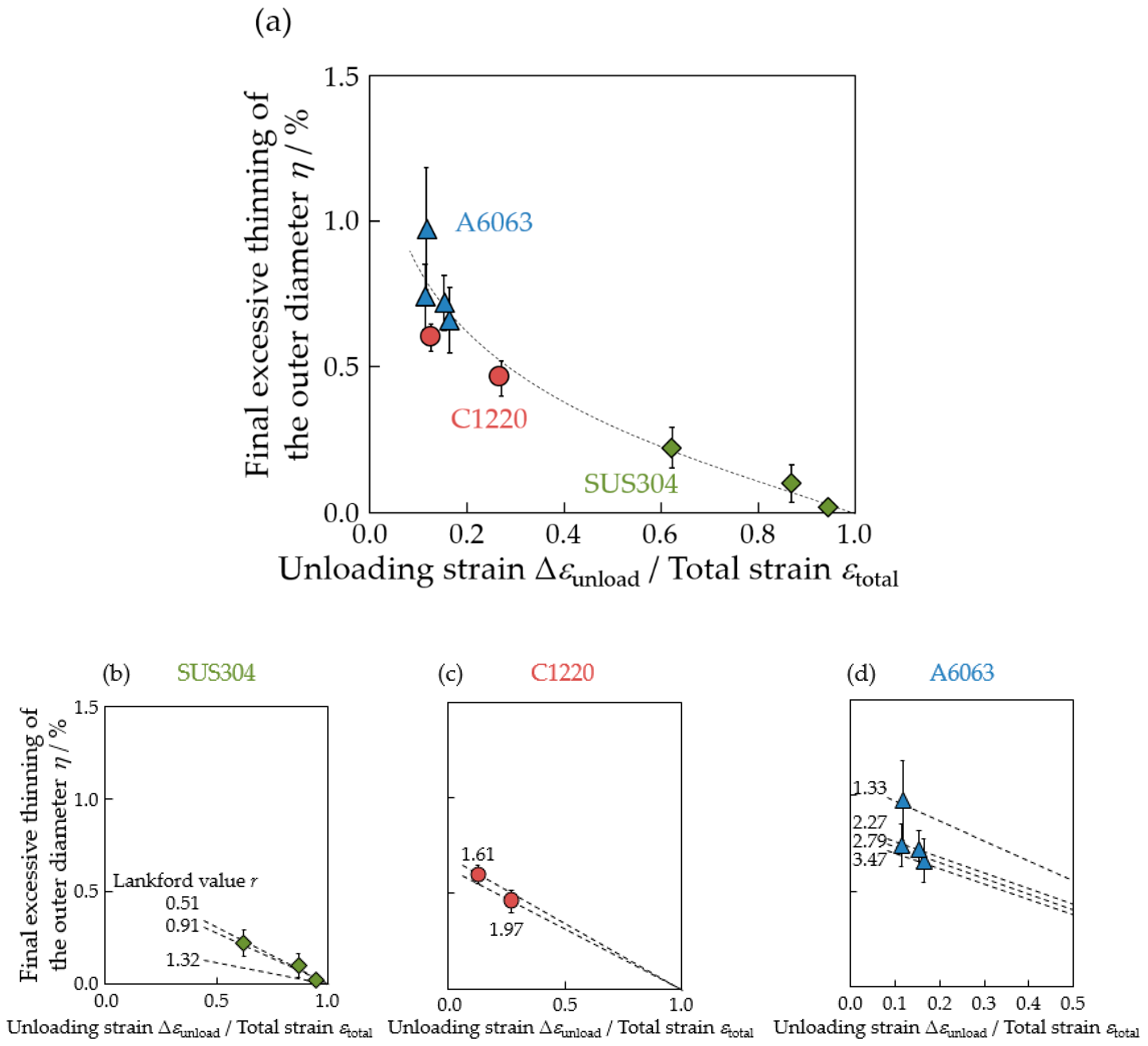
4.2.3. Excessive Thinning of the Outer Diameter after Drawing
4.2.4. Summary of Excessive Thinning of Outer Diameter
5. Conclusions
Author Contributions
Funding
Acknowledgments
Conflicts of Interest
Nomenclature
| D0 | Outer diameter of starting material (mm) |
| Ddie | Die diameter (mm) |
| Dtotal | Outer diameter of tube during drawing (mm) |
| Dn | Final outer diameter of drawn tube (mm) |
| E | Elastic modulus of bulk metal (GPa) |
| E′ | Apparent elastic modulus of tube (GPa) |
| F | Load (N) |
| FBT | Back tension during drawing (N) |
| Fl | Drawing tension during drawing (N) |
| h | Height of outer uneven surface of tube (μm) |
| H | Height from an arbitrary position of the outer uneven surface of the tube (μm) |
| Have | Average value of h (μm) |
| l0 | Length of starting material (mm) |
| ldie | Length of tube after passing through the die approach (mm) |
| ltotal | Length of tube during drawing (mm) |
| ln | Final length of tube (mm) |
| Re | Die reduction (-) |
| r | Lankford value of the tube (-) |
| t0 | Wall thickness of the starting material (mm) |
| tdie | Wall thickness of tube after passing through the die approach (mm) |
| ttotal | Wall thickness of tube during drawing (mm) |
| tn | Final wall thickness of tube (mm) |
| Vn | Drawing speed on the die’s exit side (mm/s) |
| Vn−1 | Drawing speed on the die’s entrance side (mm/s) |
| β | Drawing speed ratio (-) |
| Δεe | Elastic strain (-) |
| ΔεE | Excessive elastic strain (-) |
| εp | Plastic strain (-) |
| εtotal | Total strain (-) |
| εtrue | True strain (-) |
| Δεunload | Unloading strain (-) |
| η | Final excessive thinning of the outer diameter (%) |
| η′ | Excessive thinning of the outer diameter during drawing (%) |
| θ | Die half angle (°) |
| σl | Drawing stress (MPa) |
| σrue | True stress (MPa) |
Appendix A
References
- Favier, D.; Liu, Y.; Orgeas, L.; Sandel, A.; Debove, L.; Comte-Gaz, P. Influence of thermomechanical processing on the superelastic properties of a Ni-rich nitinol shape memory alloy. Mater. Sci. Eng. A 2006, 429, 130–136. [Google Scholar] [CrossRef]
- Xiong, S.; Wang, Q.; Chen, Y. Study on electrical conductivity of single polyani-line microtube. Mater. Lett. 2007, 61, 2965–2968. [Google Scholar] [CrossRef]
- Tsuchiya, K.; Jinnin, S.; Yamamoto, H.; Uetsuji, Y.; Nakayama, E. Design and development of a biocompatible painless microneedle by the iron sputtering deposition method. Precis. Eng. 2010, 34, 461–466. [Google Scholar] [CrossRef]
- Yoshida, K.; Furuya, H. Mandrel drawing and plug drawing of shape-memory-alloy fine tubes used in catheters and stents. J. Mater. Process. Technol. 2004, 153–154, 145–150. [Google Scholar] [CrossRef]
- Yoshida, K.; Watanabe, M.; Ishikawa, H. Drawing of Ni-Ti shape-memory-alloy fine tubes in medical tests. J. Mater. Process. Technol. 2001, 118, 251–255. [Google Scholar] [CrossRef]
- Takemoto, K. Tension control technology in non-slip type wire drawing machine. J. Jpn. Soc. Technol. Plast. 2016, 57, 1122–1125. (In Japanese) [Google Scholar] [CrossRef]
- Kishimoto, T.; Gondo, S.; Takemoto, K.; Tashima, K.; Kajino, S.; Suzuki, S. Conditions for wall thickness reduction in hollow sinking of SUS304 tubes with drawing speed control in entrance and exit sides of die. J. Manuf. Sci. Eng. 2019, 141, 111008. [Google Scholar] [CrossRef]
- Werkhoven, R.J.; Sillekens, W.H.; van Lieshout, J.B.J.M. Processing aspects of magnesium alloy stent tube. Magnes. Technol. 2011, 419–424. [Google Scholar] [CrossRef]
- Halaczek, D. Analysis of manufacturing bimetallic tubes by the cold drawing process. Arch. Metall. Mater. 2016, 61, 241–248. [Google Scholar] [CrossRef] [Green Version]
- Kishimoto, T.; Sakaguchi, H.; Suematsu, S.; Tashima, K.; Kajino, S.; Gondo, S.; Suzuki, S. Outer Diameter and Surface Quality of Micro Metal Tubes in Hollow Sinking. Procedia Manuf. 2020, 47, 217–223. [Google Scholar] [CrossRef]
- Vollertsen, F.; Hu, Z.; Niehoff, H.S.; Theiler, C. State of the art in micro forming and investigation into deep drawing. J. Mater. Process. Technol. 2004, 151, 70–79. [Google Scholar] [CrossRef]
- Armstrong, R.W. On size effects in polycrystal plasticity. J. Mech. Phys. Solids 1961, 9, 196–199. [Google Scholar] [CrossRef]
- Wang, C.; Wang, C.; DebinShan, B.; Huang, G. Size effect on flow stress in uniaxial compression of pure nickel cylinders with a few grains across thickness. Mater. Lett. 2013, 106, 294–296. [Google Scholar] [CrossRef]
- Engel, U.; Eckstein, R. Microforming-from basic research to its realization. J. Mater. Process. Technol. 2002, 125–126, 35–44. [Google Scholar] [CrossRef]
- Keller, C.; Hug, E.; Retoux, R.; Feaugas, X. TEM study of dislocation patterns in near-surface and core regions of deformed nickel polycrystals with few grains across the cross section. Mech. Mater. 2010, 42, 44–54. [Google Scholar] [CrossRef]
- Celentano, D.J.; Rosales, D.A.; Peña, J.A. Simulation and Experimental Validation of Tube Sinking Drawing Processes. Mater. Manuf. Process. 2011, 26, 770–780. [Google Scholar] [CrossRef]
- Huh, J.; Huh, H.; Lee, C.S. Effect of strain rate on plastic anisotropy of advanced high strength steel sheets. Int. J. Plast. 2013, 44, 23–46. [Google Scholar] [CrossRef]
- Kitamura, K.; Terano, M. Determination of local properties of plastic anisotropy in thick plate by small-cube compression test for precise simulation of plate forging. Manuf. Technol. 2013, 63, 293–296. [Google Scholar] [CrossRef]
- Japanese Industrial Standards Committee. JIS G 4305, Cold-Rolled Stainless Steel Plate, Sheet and Strip; Japanese Standards Association: Tokyo, Japan, 2012. [Google Scholar]
- Japanese Industrial Standards Committee. JIS H 4080, Aluminium and Aluminium Alloy Extruded Tubes and Cold-Drawn Tubes; Japanese Standards Association: Tokyo, Japan, 2015. [Google Scholar]
- Japanese Industrial Standards Committee. JIS H 3300, Copper and Copper Alloy Seamless Pipes and Tubes; Japanese Standards Association: Tokyo, Japan, 2018. [Google Scholar]
- Akiyama, M.; Matsui, K.; Terada, K. Analysis of Microscopic yielding behavior of carbon steel under macroscopic loading. Tetsu-to-Hagane 2005, 91, 803–808. [Google Scholar] [CrossRef] [Green Version]
- Zhang, J.; Nylas, A.; Obst, B. New technique for measuring the dynamic Young’s modulus between 295 and 6K. Cryogenics 1991, 31, 884–889. [Google Scholar] [CrossRef]
- Jiang, C.P.; Chen, C.C. Grain Size Effect on the springback behavior of the microtube in the press bending process. Mater. Manuf. Process. 2012, 27, 512–518. [Google Scholar] [CrossRef]
- Kuboki, T.; Nishida, K.; Sakai, T.; Murata, M. Effect of plug on levelling of residual stress in tube drawing. J. Mater. Process. Technol. 2008, 204, 162–168. [Google Scholar] [CrossRef]
- Japanese Aluminium Association. Physical Property. In Aluminim Handbook; Japanese Aluminium Association: Tokyo, Japan, 2001; pp. 26–29. [Google Scholar]


| C | Si | Mn | P | S | Ni | Cr | Fe |
|---|---|---|---|---|---|---|---|
| 0.05 | 0.79 | 1.72 | 0.035 | 0.004 | 8.88 | 18.22 | Bal. |
| Si | Fe | Cu | Mn | Mg | Cr | Zn | Al |
|---|---|---|---|---|---|---|---|
| 0.43 | 0.18 | 0.04 | 0.02 | 0.52 | 0.01 | 0.01 | Bal. |
| Die Reduction Re | Drawing Speed Ratio β (= Vn/Vn−1) | Die Half Angle θ° | |
|---|---|---|---|
| 1-chuck *1 | 2-chuck *2 | ||
| 0.05 | 1.03 | 1.05, 1.10, 1.20 | 4 |
| 0.17 | 1.08 | 1.10, 1.20, 1.50 | 4 |
| 0.29 | 1.17 | 1.20, 1.50 | 4 |
© 2020 by the authors. Licensee MDPI, Basel, Switzerland. This article is an open access article distributed under the terms and conditions of the Creative Commons Attribution (CC BY) license (http://creativecommons.org/licenses/by/4.0/).
Share and Cite
Kishimoto, T.; Sakaguchi, H.; Suematsu, S.; Tashima, K.; Kajino, S.; Gondo, S.; Suzuki, S. Deformation Behavior Causing Excessive Thinning of Outer Diameter of Micro Metal Tubes in Hollow Sinking. Metals 2020, 10, 1315. https://doi.org/10.3390/met10101315
Kishimoto T, Sakaguchi H, Suematsu S, Tashima K, Kajino S, Gondo S, Suzuki S. Deformation Behavior Causing Excessive Thinning of Outer Diameter of Micro Metal Tubes in Hollow Sinking. Metals. 2020; 10(10):1315. https://doi.org/10.3390/met10101315
Chicago/Turabian StyleKishimoto, Takuma, Hayate Sakaguchi, Saki Suematsu, Kenichi Tashima, Satoshi Kajino, Shiori Gondo, and Shinsuke Suzuki. 2020. "Deformation Behavior Causing Excessive Thinning of Outer Diameter of Micro Metal Tubes in Hollow Sinking" Metals 10, no. 10: 1315. https://doi.org/10.3390/met10101315