Article

Laser Beam Welding of Feconicrmn High-Entropy Alloys with Preplaced Powders

1
School of Materials Science and Engineering, Jiangsu University, Zhenjiang 212013, China
2
Jiangsu Key Laboratory of Advanced Structural Materials and Application Technology, School of Materials Engineering, Nanjing Institute of Technology, Nanjing 211167, China
*
Authors to whom correspondence should be addressed.
Metals 2020, 10(11), 1402; https://doi.org/10.3390/met10111402
Submission received: 24 September 2020 / Revised: 18 October 2020 / Accepted: 21 October 2020 / Published: 22 October 2020

Abstract

:
In this paper, as-annealed FeCoNiCrMn plates were laser-welded with preplaced FeCoNiCrMn and FeCoNiCrAl powders, respectively. The grains in the fusion zone of the weld with FeCoNiCrMn powder have a reduced aspect ratio compared to those without preplaced powders and the weld with FeCoNiCrAl powder presents relative equiaxed grains. The yield strength of each weld has been remarkably enhanced when referring to the base alloy, and the ultimate tensile strength of each weld with preplaced powder exceeds 80% of that of the base and the maximum reaches 88.5% when referring to the weld with preplaced FeCoNiCrMn powder. Cleavage fractography was observed in the welds. The finding of this work will service the engineering practices of high-entropy alloys.

1. Introduction

The design concept of high-entropy alloys (HEAs) is out of the limitations in traditional alloys which put the compositions in the corner of phase diagrams, and this kind of novel alloy design approach has been paid much attention in the past two decades [1]. The classic HEAs systems usually consist of five transition metallic elements with nearly equimolar proportions, such as FeCoNiCrMn, FeCoNiCrAl, TaNbHfZrTi and NbTaMoWV [2,3]. As demonstrated, different from austenitic stainless and other FeNi-based steels, the tensile properties and toughness of HEAs are not significantly deteriorated at low temperatures and are even superior to those at room temperature in many cases due to nano-twin mechanisms [4].
For extending the use of HEAs to engineering applications, welding performance is usually considered and has attracted interests both in the academic and industrial communities [5]. Up to date, friction stir welding, gas tungsten arc, electron-beam welding and laser welding have been reported [6,7,8]. Comparatively, laser welding has a higher welding rate and is preferable to large-volume processing. During processing, laser welding offers a focused heat source and facilitates the formation of a deeply narrow weld zone [6,9,10]. On the other hand, laser welding restricts the extension of the heat-affected zone and thus minimizes the deformation of welded parts [11]. For the strengthening of welds, laser beam welding overcomes the softening of the weld joint of FeCoNiCrMn HEA via the precipitation of the B2 phases during the solidification of the fusion zone and takes advantage of the “intrinsic” hardening of HEAs [12]; Chen et al. fabricated a crack- and void-free weld joint of an FeCoNiCrMn HEA by laser welding and disclosed that the Mn-C-rich precipitates facilitate the strengthening of the base by means of the pinning effect on dislocations and boundaries [13]. Furthermore, the laser welding of FeCoNiCrMn HEA has shown suitability for cryogenic applications due to the formation of deformation twins and dislocations [14].
Previous studies on the laser welding of HEAs mainly focus on the weldability of base HEAs manufactured by different methods [12,15] or on the feasibility of HEAs as filler metals [16,17]. Nevertheless, laser welding with preplacing HEA powders in the gap between base HEAs is worthy to be noticed due to its application in the rehabilitation of HEA-based parts in future engineering. Alternatively, by changing the powders, the preplaced powders during the welding provide different solutions for enhancing the strength of weld joints. In this work, the base, FeCoNiCrMn HEA, was laser-welded with preplaced FeCoNiCrMn or FeCoNiCrAl powders, and the microstructures and tensile properties of welds were investigated.

2. Experiments

2.1. Preparation of Materials and Laser Welding

Master alloy ingot with the nominal composition Fe20Co20Cr20Ni20Mn20 (at%) was synthesized by the induction melting of a mixture of pure elemental metals (purity: 99.9% or higher) in a vacuum furnace (WK-II, PHYSOE, Beijing, China). The bulk HEA specimen was prepared by casting into a graphite mold with a cavity of 140 (L) × 30 (W) × 28 mm (H). The as-cast HEA was homogenized at 1100 °C for 24 h and then quenched with water. The specimen was rolled with 30% reduction in height and finally was annealed at 800 °C for 1 h. The plates with a dimension of 15 × 95 × 1.6 mm for laser welding were cut by electric discharge machining. The powders were provided by Jiangsu Vilory company and the mean size of the powder was ≤25 µm.
The laser welding was carried on a welding platform (TRUDISK 6002, TRUMPF, Ditzingen, Germany). The two HEA plates were fixed with a 1 mm of gap along the cross-sections where the powder was preplaced. For the convenience of preplacing, the powder was immersed in acetone for 0.5 h and the mortar-like powder at the bottom was used in welding experiments. The power was set at 2.0 KW, the defocusing was fixed at 0.0 mm above the surface of the specimen and the welding speed was 3.0 m/min. For suppressing the oxidation, the argon shielding gas was utilized and the gas flow rate was 8L/min. Figure 1 shows the schematic diagram for the laser welding. The welding without preplaced powder was also carried out as a controlled experiment. In this case, the two HEA plates were set in contact with each other, and other conditions were the same as the experiments with preplaced powders.

2.2. Characterization and Tensile Tests

The components of the phases of powders and the base metal were ascertained by X-ray diffraction (XRD) (D8 ADVANCE, Bruker, karlsruhe, Germany) with a scanning rate of 5°/min (2θ). Optical microscopy (Axio Imager M2m, Zeiss, Germany) was utilized to observe the microstructures. Prior to optical microscopical observation, the specimens cut from the as-annealed samples were carefully polished into mirror by silica paper (2000 grit) and diamond reagent (particle size: 0.15 µm) and then etched by an acid mixture (HNO3/HF = 3:1). Scanning electron microscopy (SEM) (Nova Nano 450, FEI, Hillsboro, OR, USA) equipped with energy-dispersive spectrometry (EDS) was used to determine the microstructures and compositions of welds. The fractographies of fractured specimens were also recorded by SEM.
Tensile samples were electric-discharge-machined to dog-bone tensile specimens with dimensions of 10 (L) × 2 (W) × 1.6 mm (H) in the gauge geometry. The tensile strain rate was set at 0.18 mm∙min−1. The experiments were performed on a mechanical tester (AGS-10, SHIMADZU, Kyoto, Japan) at room temperature. The surfaces of specimens in the gauge geometry were carefully mechanically polished with silica paper (2000 grit).

3. Results and Discussion

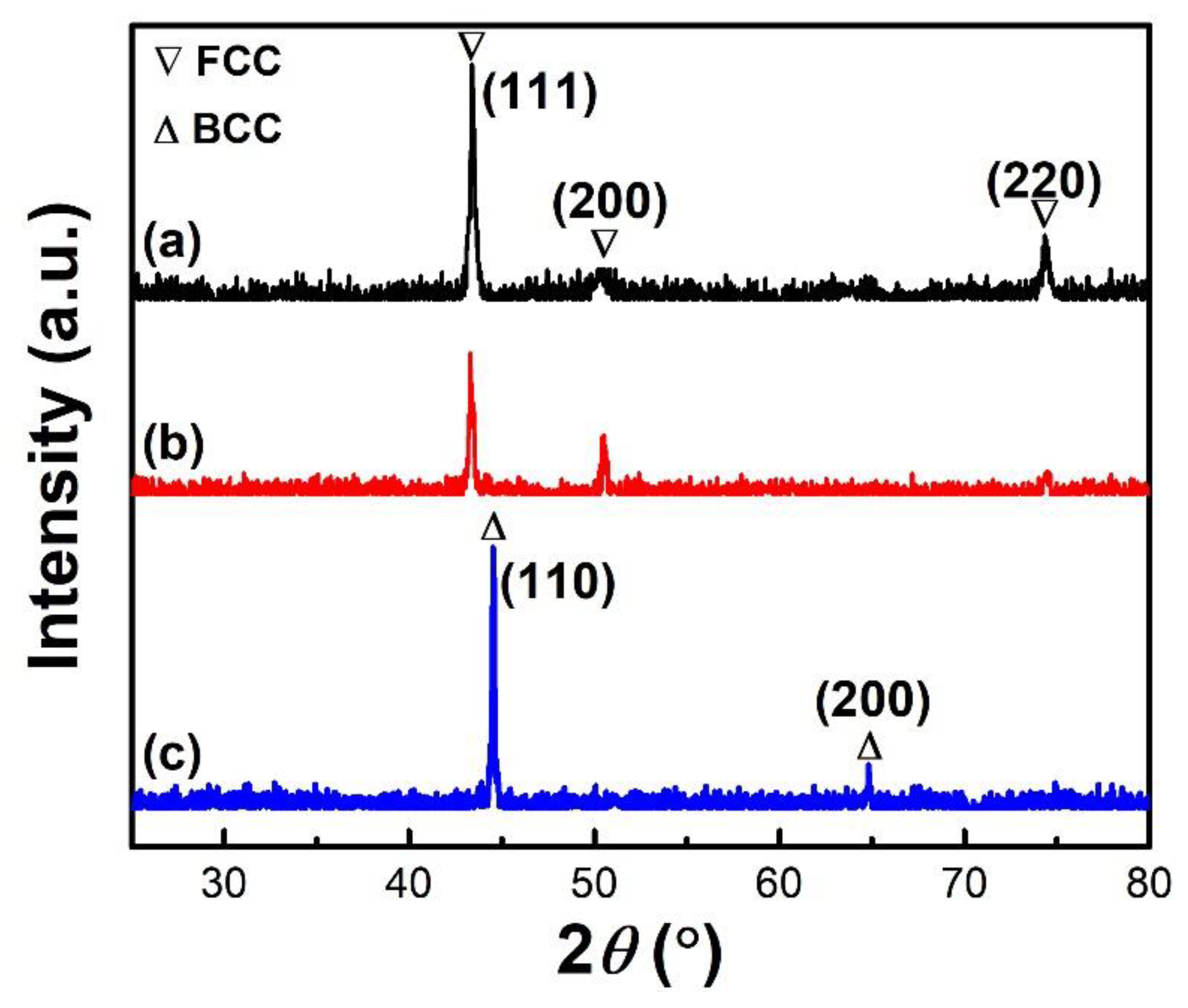
Figure 2 presents the XRD patterns of the as-annealed FeCoNiCrMn plate (which is denoted by “base” for simplification hereinafter) and commercial FeCoNiCrMn and FeCoNiCrMn powders. Clearly, the base and FeCoNiCrMn powder are of a single FCC structure and the FeCoNiCrAl powder shows a single BCC structure. From Figure S1a (in Supplementary Materials), it can be clearly seen that the base has a single phase with cellular grains and the EDS spectrum suggests that the alloy consists of a nearly equimolar ratio of elements (Figure S1b). Noticeably, the quantity of Mn and Ni elements in the base alloy is slightly less than the designed compositions due to the burn-off during the fabrication in the induction melting process.
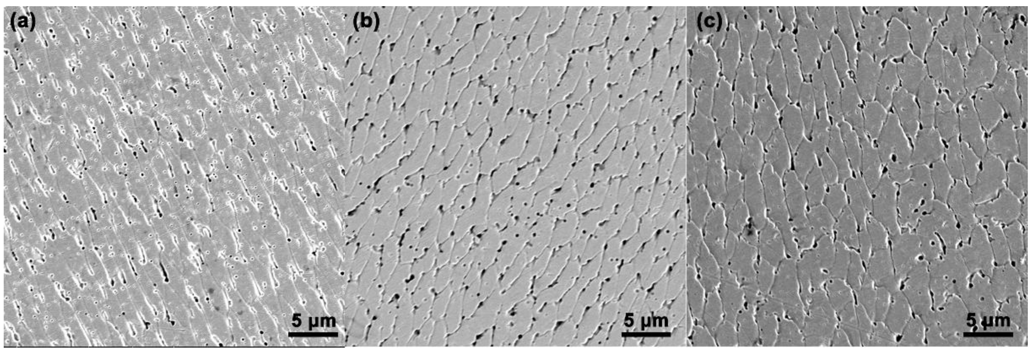
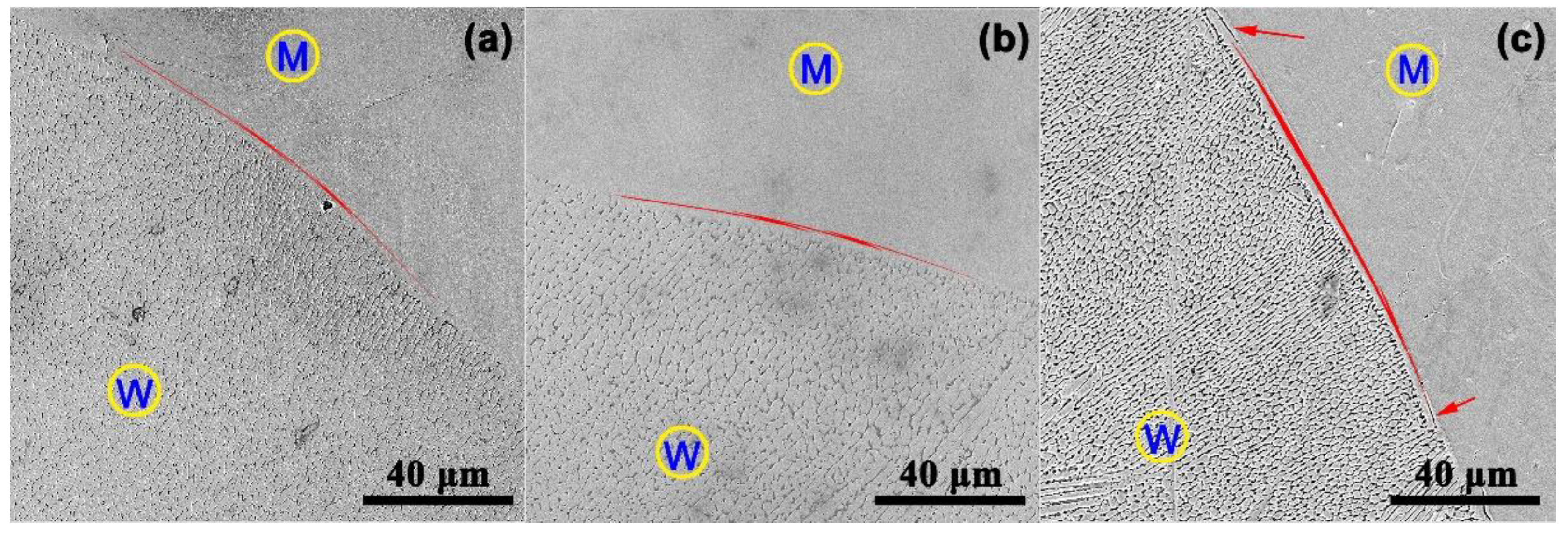
Theoretically, laser beam processing generally produces a rapid cooling rate which can promote the refinement of grains in the cast microstructure [18,19]. In the current work, the fusion zone of the weld without preplaced powder (W1) indicates elongated grains (Figure 3a). Obviously, it has a distinguished difference with the microstructures of the base. For the fusion zone of the weld with FeCoNiCrMn powder (W2), the aspect ratio has been remarkably reduced (Figure 3b), and for the weld with FeCoNiCrAl powder (W3), it presents relative equiaxed grains (Figure 3c). On the other hand, the growth of grains in the fusion zone usually is initiated at the fusion line (Figure 4), and the grains tend to grow in the direction perpendicular to the solid/liquid interface due to the maximum temperature gradient and heterogenous nucleation, and this case has been reported in previous works [20,21]. Compared with W1 and W2 (Figure 4a,b), around the fusion line of W3 (Figure 4c), it can be seen as a clear crack located in the transition region.
Table 1 shows the EDS analysis of the chemical compositions of the welds of W1, W2 and W3 specimens, respectively. Compared with the base, just a minor deviation in compositions can be detected in Fe, Co, Ni and Cr elements. Nevertheless, the noticeable deviation of compositions is observed in the Mn and Al elements. The latter is caused by the use of the Al element in the powder diffuse into the heat-affected area of W3, while the loss of the Mn element in the weld can be attributed to its low saturated vapor pressure. Evidently, even in this rapid processing technique, the loss of the Mn element can still occur. Figure S2 (in Supplementary Materials) indicates the compositional transition from the matrix to the welds of W1, W2 and W3. Reasonably, from the matrix to the weld, the quantity of Mn slightly decreases for W1 and W2 (Figure S2a,b). However, the decrease for W3 is more evident and, in the weld, a strong decrease trace can be monitored (Figure S2c). On the other hand, the quantity of the Al element increases from the matrix to weld (Figure S2d). The existence of the Al element in the matrix should be attributed to its diffusion with a heat effect.
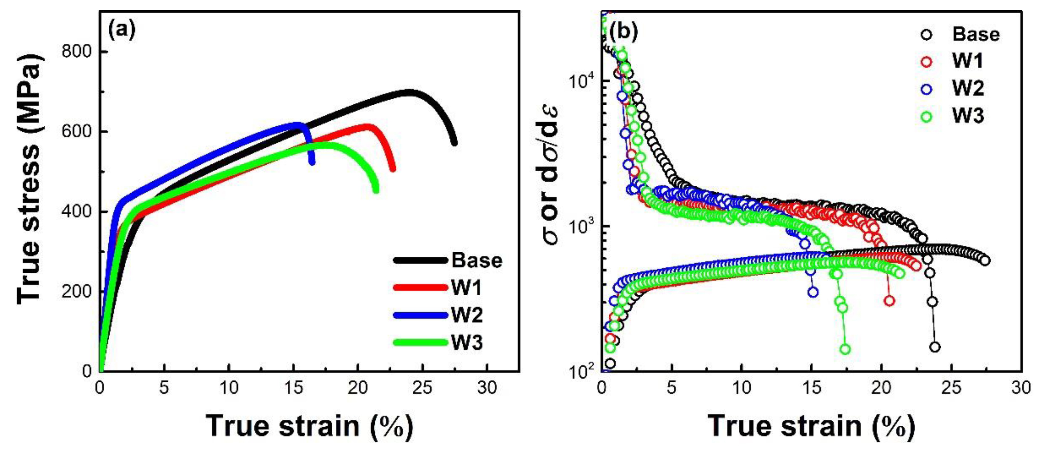
Figure 5 presents the true stress–true strain curves and work-hardening rates of the weldment and base. Evidently, the yield strength (σy) of each weldment has been remarkably enhanced and the maximum value can be reached for W2 (330.5 MPa) (Figure 5a and Table S1 in Supplementary Materials). However, as reported in previous works of the laser welding of alloys, the ultimate tensile strength (σUTS) indicates a reduction with regard to the base materials, 75% of retention (σUTS(weld)/σUTS(base)) is a preferable outcome [22,23] and the retention for HEAs is lower than other alloys [6,14,24]. The σUTS of W1, W2 and W3 reaches 87.8%, 88.5% and 81.7% when referring to the base. The preferable retention can be attributed to the similar work-hardening rates (dσ/dε) of welds to those of the base (Figure 5b).
According to Considère’s criterion [25,26], the instability of plastic deformation occurs after the intersection of the dσ/dε curve and true stress–true strain curve, and it can reflect the elongation of weldments. In the current work, the dσ/dε curves of the base, W1, W2 and W3 intersect with the corresponding tensile curves at 23.1%, 20.3%, 16.6% and 14.7%, respectively (Figure 5b), which approximately equal the values of the elongation of their counterparts (Table S1). As shown in Figure 5, the fusion line of W3 consists of some cracks and this case has not taken place in W1 and W2. This case strongly weakens the stability of plastic deformation. Summarily, laser welding with preplaced powders can promote the tensile properties, especially the powder with the same compositions as the base. The main reason for this case may be the higher wettability of the same composition than different compositions.
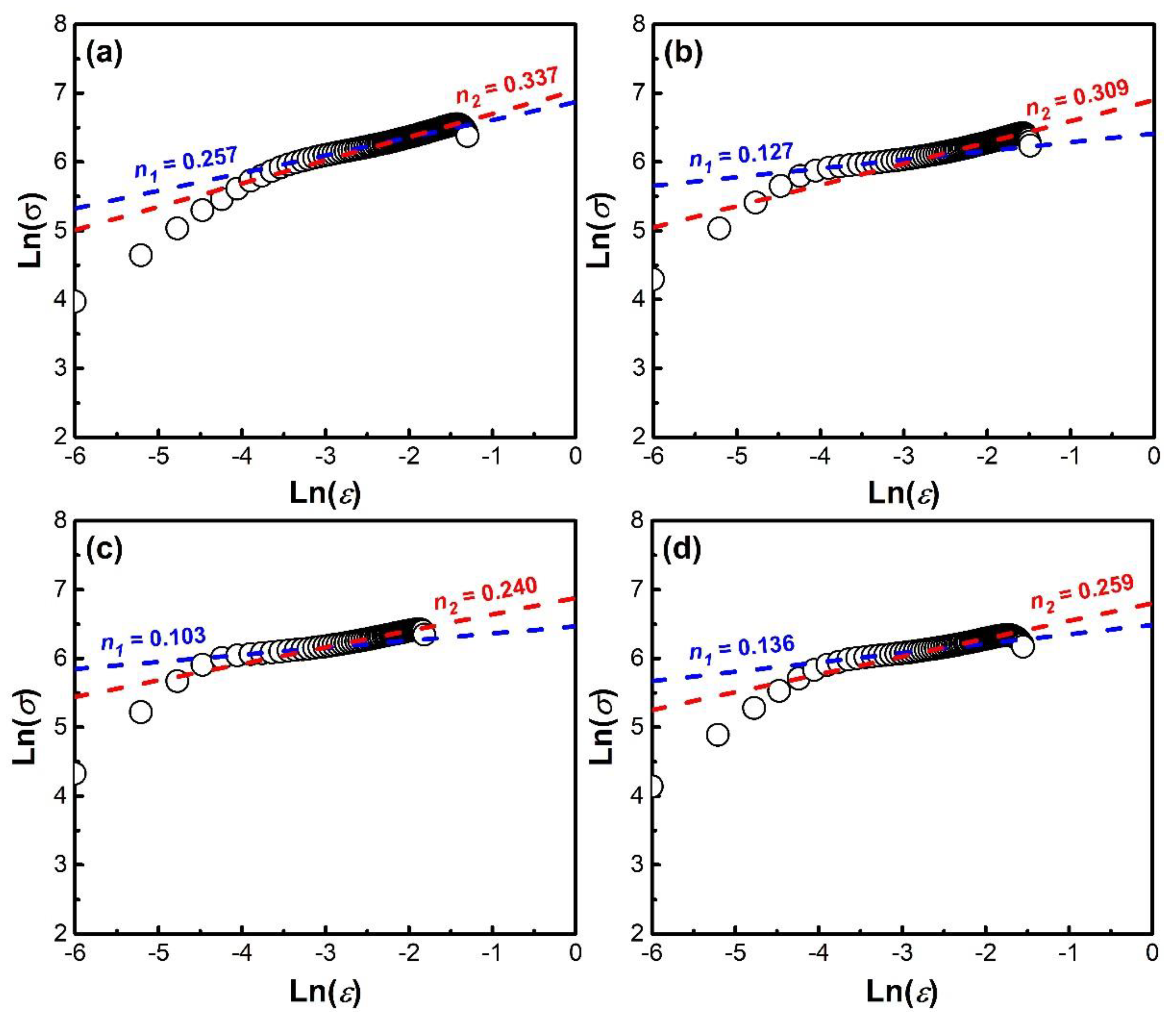
The ln(σ)-ln(ε) plots verify the two-step hardening during the deformation of the base and weldments in the current work (Figure 6), according to the Holloman equation (σ = K·εn (also written as ln(σ) = n·ln(ε) + const.), where n is the work-hardening exponent) [25]. Specifically, for the first stage, the values of n1 of weldments are smaller than those of the base, suggesting that the maximum strength can be easily achieved; the second stage of hardening indicates that W1 has a larger n2 (0.309) than W2 (0.240) and W3 (0.259), which is the response of the hardening of the base HEA. On this point, both n1 and n2 for W2 are relatively smaller than others and this is responsible for the cooperation deformation of the weld and matrix. Figure 7 shows the fractographies of the as-fractured base alloy and weldments. To be specific, the fractographies of W1 (Figure 7b) are similar to those of the base (Figure 7a), but the size of dimples of the base (Figure S3a in Supplementary Materials) is larger than that of W1 (Figure S3b in Supplementary Materials). On the other hand, in several regions of the fractographies of W1, there exist quasi-cleavage features. However, the fractographies of both W2 and W3 indicate a cleavage feature (Figure 7c,d), agreeing with the reduction in elongation.

4. Conclusions

In the current work, the as-annealed FeCoNiCrMn plates were laser-welded without or with placed powers. The main conclusions are summarized as follows:
(1)
The fusion zone of W1 indicates elongated grains, but the aspect ratio of the fusion zone of W2 has been remarkably reduced, and W3 presents relative equiaxed grains. Noticeable deviation of compositions is observed in the Mn and Al elements, implying that even in this rapid processing technique, the loss of the Mn element can still occur.
(2)
The yield strength (σy) of each weldment has been remarkably enhanced and the maximum value can be reached for W2 (330.5 MPa). The σUTS of W1, W2 and W3 reaches 87.8%, 88.5% and 81.7% when referring to the base. Laser welding with preplaced powders can promote tensile properties.
(3)
The fractographies of W1 are similar to those of the base, but the size of the dimples of the base is larger than that of W1. However, the fractographies of both W2 and W3 indicate a cleavage feature, agreeing with the reduction in elongation.

Supplementary Materials

The following are available online at https://www.mdpi.com/2075-4701/10/11/1402/s1, Figure S1: Microstructure of the base (a) and EDS spectrum of the position with marker (○)(b); Figure S2: Compositional transition from matrix to weld of the Mn element ((a) W1; (b) W2 and (c) W3) and that of the Al element for W3 (d) (the scale “0” denotes the fusion line in each weld); Figure S3: Fractographies contrast of the base (a) and W1 (b); Table S1: The tensile properties of the base and weldments.

Author Contributions

Z.Z.: investigation, writing-original draft. F.Z.: data curation. J.W.: supervision, writing—review & editing, funding acquisition. J.P.: validation, methodology. F.C.: funding acquisition, writing—review & editing. All authors have read and agreed to the published version of the manuscript.

Funding

Thanks for financial support from the National Natural Science Foundation of China (grant numbers 51601050), Jiangsu key laboratory for advanced metallic materials (grant number BM2007204), the Opening Project of Jiangsu Key Laboratory of Advanced Structural Materials and Application Technology (No. ASMA201702) and Natural Science Foundation of Jiangsu Province (No. BK20170543).

Conflicts of Interest

The authors declare no conflict of interest.

References

  1. Yeh, J.W.; Chen, S.K.; Lin, S.J.; Gan, J.Y.; Chin, T.S.; Shun, T.T.; Tsau, C.-H.; Chang, S.-Y. Nanostructured high-entropy alloys with multiple principal elements: Novel alloy design concepts and outcomes. Adv. Eng. Mater. 2004, 6, 299–303. [Google Scholar] [CrossRef]
  2. Zhang, Y.; Zuo, T.T.; Tang, Z.; Gao, M.C.; Dahmen, K.A.; Liaw, P.K.; Lu, Z.P. Microstructures and properties of high-entropy alloys. Prog. Mater. Sci. 2014, 61, 1–93. [Google Scholar] [CrossRef]
  3. Liu, Y.Y.; Chen, Z.; Shi, J.C.; Wang, Z.Y.; Zhang, J.Y. The effect of Al content on microstructures and comprehensive properties in AlxCoCrCuFeNi high entropy alloys. Vacuum 2019, 161, 143–149. [Google Scholar] [CrossRef]
  4. Bernd, G.; Anton, H.; Dhiraj, C.; Chang, E.H.; George, E.P.; Ritchie, R.O. A fracture-resistant high-entropy alloy for cryogenic applications. Science 2014, 345, 1153. [Google Scholar]
  5. Wu, Z.; David, S.A.; Feng, Z.; Bei, H. Weldability of a high entropy CrMnFeCoNi alloy. Scr. Mater. 2016, 124, 81–85. [Google Scholar] [CrossRef] [Green Version]
  6. Guo, J.; Tang, C.; Rothwell, G.; Li, L.S.; Wang, Y.C.; Yang, Q.X.; Ren, X.J. Welding of high entropy alloys A Review. Entropy 2019, 21, 431. [Google Scholar] [CrossRef] [Green Version]
  7. Li, P.; Sun, H.T.; Wang, S.; Hao, X.H.; Dong, H.G. Rotary friction welding of AlCoCrFeNi2.1 eutectic high entropy alloy. J. Alloy. Compd. 2020, 814, 152322. [Google Scholar] [CrossRef]
  8. Arab, A.; Guo, Y.S.; Zhou, Q.; Chen, P.W. Joining AlCoCrFeNi high entropy alloys and Al-6061 by explosive welding method. Vacuum 2020, 174, 109221. [Google Scholar] [CrossRef]
  9. Reddy, C.K.; Krishna, M.G.; Srikant, P. Brief evolution story and some basic limitations of high entropy alloys (heas)–A review. Mater. Today Proc. 2019, 18, 436–439. [Google Scholar] [CrossRef]
  10. Sokkalingam, R.; Sivaprasad, K.; Duraiselvam, M.; Muthupandi, V.; Prashanth, K.G. Novel welding of Al0.5CoCrFeNi high-entropy alloy: Corrosion behavior. J. Alloy. Compd. 2020, 817, 153163. [Google Scholar] [CrossRef]
  11. Benyounis, K.Y.; Olabi, A.G.; Hashmi, M.S.J. Effect of laser welding parameters on the heat input and weld-bead profile. J. Mater. Process. Technol. 2005, 164, 978–985. [Google Scholar] [CrossRef] [Green Version]
  12. Kashaev, N.; Ventzke, V.; Stepanov, N.; Shaysultanov, D.; Sanin, V.; Zherebtsov, S. Laser beam welding of a CoCrFeNiMn-type high entropy alloy produced by self-propagating high-temperature synthesis. Intermetallics 2018, 96, 63–71. [Google Scholar] [CrossRef]
  13. Chen, Z.; Wang, B.F.; Duan, B.H.; Zhang, X.Y. Mechanical properties and microstructure of laser welded FeCoNiCrMn high-entropy alloy. Mater. Lett. 2020, 262, 127060. [Google Scholar] [CrossRef]
  14. Nam, H.; Park, C.; Moon, J.; Na, Y.; Kim, H.; Kang, N. Laser weldability of cast and rolled high-entropy alloys for cryogenic applications. Mater. Sci. Eng. A 2019, 742, 224–230. [Google Scholar] [CrossRef]
  15. Nam, H.; Park, S.; Chun, E.-J.; Kim, H.; Na, Y.; Kang, N. Laser dissimilar weldability of cast and rolled CoCrFeMnNi high-entropy alloys for cryogenic applications. Sci. Technol. Weld. Join. 2019, 2, 1–8. [Google Scholar] [CrossRef]
  16. Nam, H.; Park, S.; Park, N.; Na, Y.; Kim, H.; Yoo, S.J.; Moon, H.Y.; Kang, N. Weldability of cast CoCrFeMnNi high-entropy alloys using various filler metals for cryogenic applications. J. Alloy. Compd. 2020, 819, 153278. [Google Scholar] [CrossRef]
  17. Dong, K.W.; Kong, J.; Yang, Y.; Peng, Y.; Zhou, Q.; Wang, K.H. Achieving high-strength joining of TiAl- and Ni-based alloys at room temperature and 750 degrees via utilizing a quinary FeCoNi-based amorphous filler. J. Mater. Res. Technol. JMRT 2020, 9, 1955–1965. [Google Scholar] [CrossRef]
  18. Zhang, H.; Pan, Y.; He, Y.Z. Grain refinement and boundary misorientation transition by annealing in the laser rapid solidified 6FeNiCoCrAlTiSi multicomponent ferrous alloy coating. Surf. Coat. Technol. 2011, 205, 4068–4072. [Google Scholar] [CrossRef]
  19. Attar, H.; Bonisch, M.; Calin, M.; Zhang, L.C.; Scudino, S.; Eckert, J. Selective laser melting of in situ titanium-titanium boride composites: Processing, microstructure and mechanical properties. Acta Mater. 2014, 76, 13–22. [Google Scholar] [CrossRef]
  20. Bayraktar, E.; Kaplan, D.; Devillers, L.; Chevalier, J.P. Grain growth mechanism during the welding of interstitial free (IF) steels. J. Mater. Process. Technol. 2007, 189, 114–125. [Google Scholar] [CrossRef]
  21. Kurz, W.; Bezencon, C.; Gaumann, M. Columnar to equiaxed transition in solidification processing. Sci. Technol. Adv. Mater. 2001, 2, 185–191. [Google Scholar] [CrossRef]
  22. Cao, X.; Jahazi, M.; Immarigeon, J.P.; Wallace, W. A review of laser welding techniques for magnesium alloys. J. Mater. Process. Technol. 2006, 171, 188–204. [Google Scholar] [CrossRef]
  23. Kashaev, N.; Ventzke, V.; Cam, G. Prospects of laser beam welding and friction stir welding processes for aluminum airframe structural applications. J. Manuf. Process. 2018, 36, 571–600. [Google Scholar] [CrossRef]
  24. Martin, A.C.; Fink, C. Initial weldability study on Al0.5CrCoCu0.1FeNi high-entropy alloy. Weld. World 2019, 63, 739–750. [Google Scholar] [CrossRef]
  25. Meyers, M.A.; Chawla, K.K. Mechanical Behavior of Materials; Cambridge University Press: Cambridge, UK, 2013. [Google Scholar]
  26. Chen, B.; Moon, S.K.; Yao, X.; Bi, G.; Shen, J.; Umeda, J.; Kondoh, K. Strength and strain hardening of a selective laser melted AlSi10Mg alloy. Scr. Mater. 2017, 141, 45–49. [Google Scholar] [CrossRef]
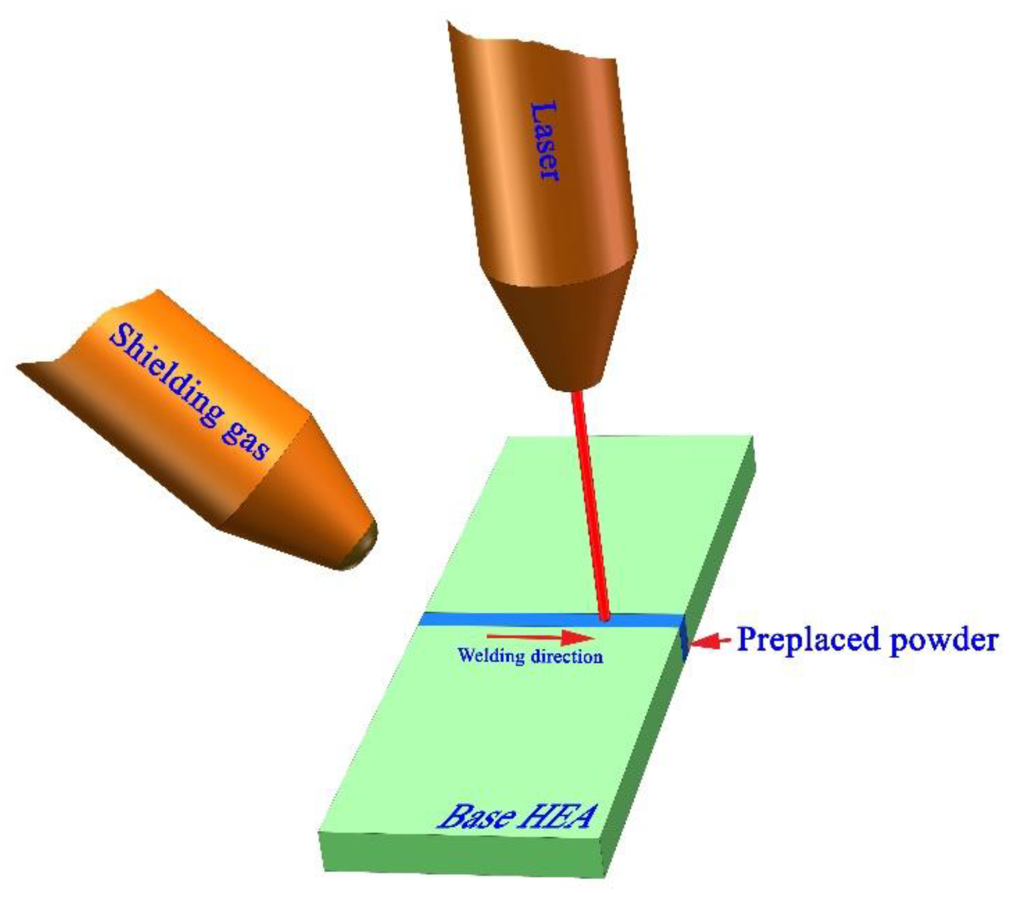
Figure 1. Schematic diagram of laser welding with preplaced powder.
Metals 10 01402 g001
Figure 2. XRD patterns for base metal and powders: (a) as-annealed FeCoNiCrMn plate; (b) commercial FeCoNiCrMn powder; (c) commercial FeCoNiCrAl powder.
Metals 10 01402 g002
Figure 3. Microstructures of welds without preplaced powder (a,b) with FeCoNiCrMn powder and (c) FeCoNiCrAl powder.
Metals 10 01402 g003
Figure 4. Transition region from weld to matrix. (a) W1; (b) W2; (c) W3 (the markers “M” and “W” denote the matrix and weld, respectively; the red line illustrates the fusion line and red arrows in (c) indicate the cracks).
Metals 10 01402 g004
Figure 5. True stress–true strain curves of weldments (a) and work-hardening rate (dσ/dε) curves (b).
Metals 10 01402 g005
Figure 6. ln(σ)-ln(ε) plots of the base (a), W1 (b), W2 (c) and W3 (d).
Metals 10 01402 g006
Figure 7. Fractographies of the base (a), W1 (b), W2 (c) and W3 (d).
Metals 10 01402 g007
Table 1. EDS analysis (point) of welds (wt.%) compared with that of the base.
SampleFeCoNiCrMnAl
Base23.9719.9719.2720.1816.62/
W125.9020.7018.5821.8312.98/
W226.0620.9419.1520.8013.04/
W325.4020.5818.2620.7211.933.10
Publisher’s Note: MDPI stays neutral with regard to jurisdictional claims in published maps and institutional affiliations.