Metallurgical Model of Diffusible Hydrogen and Non-Metallic Slag Inclusions in Underwater Wet Welding of High-Strength Steel


Abstract
:1. Introduction
2. Materials and Methods
3. Results and Discussion
4. Conclusions
- (1)
- This work proposed a model of metallurgical and electrochemical processes in underwater wet welding in a vapor–gas bubble, molten slag, and liquid weld pool based on a thermodynamic modeling for the optimization of the gas–slag system and the improvement of the quality of welds. Thermodynamic modeling and experiments showed that a complex mechanism based on reducing the partial pressure of H2O, H2, H, and OH in the atmosphere of the arc and in the vapor–gas bubble and increasing the hydroxyl capacity of the basic slag system can be used to reduce the diffusible hydrogen content and slag inclusions in underwater wet welding of high-strength steel. This solution is achieved by increasing the metallurgical activity of the gas–slag system in removal of water vapor, hydrogen, and hydroxyl in reactions with the formation of HF and ionic dissolution of water vapor in the form of hydroxyl groups OH in the basic fluorine-containing slag of the TiO2–CaF2–Na3AlF6 system of the flux-cored wire.
- (2)
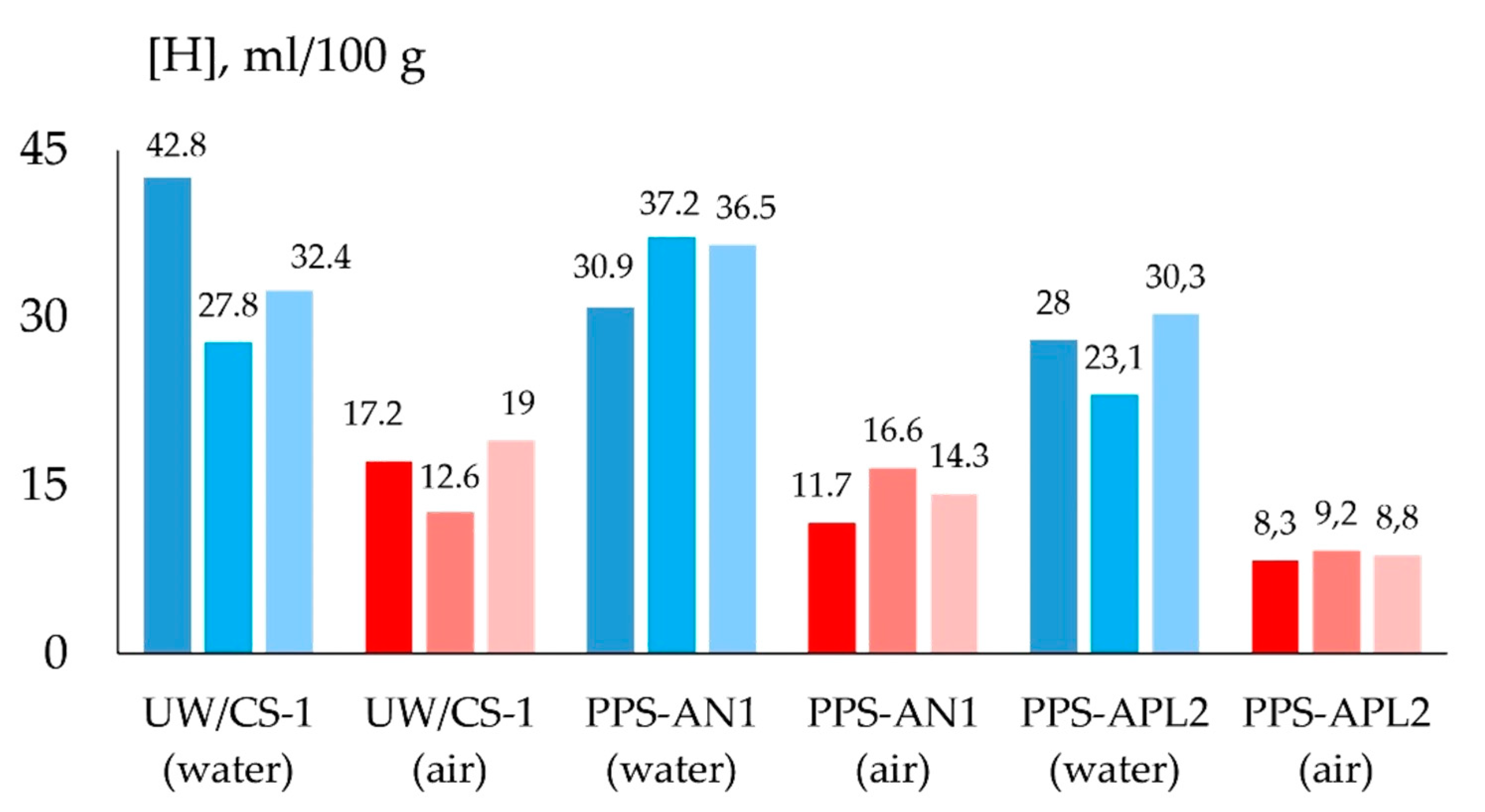
- The oxidizing potential of the atmosphere of the arc and the vapor–gas bubble decreases with an increase in fluorides, which improves the transition coefficient of the alloying elements and the density of the deposited metal and reduces the volume of slag inclusions. As a result of using a flux-cored wire with a TiO2–CaF2–Na3AlF6 system, the average strength and impact toughness of the weld increased by 8 and 22%, respectively, and the diffusible hydrogen content decreased by 21% compared to a flux-cored wire with a TiO2–Fe2O3 system.
Author Contributions
Funding
Acknowledgments
Conflicts of Interest
References
- Çolak, Z.; Ayan, Y.; Kahraman, N. Weld morphology and mechanical performance of marine structural steel welded underwater in a real marine environment. Int. J. Adv. Manuf. Technol. 2020, 109, 491–501. [Google Scholar] [CrossRef]
- Surojo, E.; Putri, E.D.W.S.; Budiana, E.P.; Triyono. Recent developments on underwater welding of metallic material. Procedia Struct. Integr. 2020, 27, 14–21. [Google Scholar] [CrossRef]
- ANSI/AWS D3.6M:2017. Underwater Welding Code, 6th ed.; American Welding Society: Miami, FL, USA, 2017. [Google Scholar]
- Tomków, J.; Fydrych, D.; Rogalski, G. Role of bead sequence in underwater welding. Materials 2019, 12, 3372. [Google Scholar] [CrossRef] [PubMed] [Green Version]
- Arias, R.; Bracarense, A.Q. Fatigue crack growth assessment in underwater wet welds. Weld. J. 2017, 8, 287–294. [Google Scholar]
- Gao, W.B.; Wang, D.P.; Cheng, F.J.; Deng, C.Y.; Xu, W. Underwater wet welding for HSLA steels: Chemical composition, defects, microstructures, and mechanical properties. Acta Metall. Sin. 2015, 28, 1097–1108. [Google Scholar] [CrossRef]
- Chen, H.; Guo, N.; Zhang, X.; Zhou, L.; Wang, G. Effect of water flow on the microstructure, mechanical performance, and cracking susceptibility of underwater wet welded Q235 and E40 steel. J. Mater. Process. Technol. 2020, 277, 103–115. [Google Scholar] [CrossRef]
- Parshin, S.G. The Metallurgy of Underwater and Hyperbaric Welding, 1st ed.; Polytechnic University Publishing House: Saint Petersburg, Russia, 2016. (In Russian) [Google Scholar]
- Santos, V.R.; Monteiro, M.J.; Rizzo, F.C.; Bracarense, A.Q.; Pessoa, E.C.P.; Marinho, R.R.; Vieira, L.A. Development of an oxyrutile electrode for wet welding. Weld. J. 2012, 91, 319–328. [Google Scholar]
- Shi, Y.; Hu, Y.; Yi, Y.; Lin, S.; Li, Z. Porosity and microstructure of underwater wet FCAW of duplex stainless steel. Metallogr. Microstruct. Anal. 2017, 6, 383–389. [Google Scholar] [CrossRef]
- Chen, H.; Guo, N.; Xu, K.; Xu, C.; Zhou, L.; Wang, G. In-situ observations of melt degassing and hydrogen removal enhanced by ultrasonics in underwater wet welding. Mater. Des. 2020, 188, 1–14. [Google Scholar] [CrossRef]
- Yang, Q.; Han, Y.; Jia, C.; Wu, J.; Dong, S.; Wu, C. Impeding effect of bubbles on metal transfer in underwater wet FCAW. J. Manuf. Process. 2019, 45, 682–689. [Google Scholar] [CrossRef]
- Wang, J.; Sun, Q.; Zhang, T.; Xu, P.; Feng, J. Experimental study of arc bubble growth and detachment from underwater wet FCAW. Weld. World 2019, 63, 1747–1759. [Google Scholar] [CrossRef]
- Feng, J.; Wang, J.; Sun, Q.; Zhao, H.; Wu, L.; Xu, P. Investigation on dynamic behaviors of bubble evolution in underwater wet flux-cored arc welding. J. Manuf. Process. 2017, 28, 156–167. [Google Scholar] [CrossRef]
- Ando, S.; Asahina, T. A study on the metallurgical properties of steel welds with underwater gravity welding. In Proceedings of the Underwater Welding International Conference, Trondheim, Norway, 27–28 June 1983. [Google Scholar]
- Gretsky, Y.Y.; Maksimov, S.Y.; Kravchenko, N.V. Influence of marble in rutile electrode coating on hydrogen content in weld metal during underwater welding. Autom. Weld. 1993, 7, 51–52. (In Russian) [Google Scholar]
- Silva, W.C.D.; Bracarense, A.Q.; Pessoa, E.C.P. Effect of water depth on diffusible hydrogen on wet welds. Soldagem Inspeção 2012, 4, 298–305. [Google Scholar] [CrossRef] [Green Version]
- Kirchheim, R.; Pundt, A. Hydrogen in metals. In Physical Metallurgy, 5th ed.; Laughlin, D., Hono, K., Eds.; Elsevier: Amsterdam, The Netherlands, 2014; pp. 2597–2705. [Google Scholar]
- Chen, H.; Guo, N.; Shi, X.; Du, Y.; Feng, J.; Wang, G. Effect of hydrostatic pressure on protective bubble characteristic and weld quality in underwater flux-cored wire wet welding. J. Mater. Process. Technol. 2018, 259, 159–168. [Google Scholar] [CrossRef]
- Kakhovs’kyi, M.Y. Influence of aqueous media on the gas saturation of weld metal in the course of underwater welding of 12KH18N10T steel. Mater. Sci. 2016, 51, 843–846. [Google Scholar] [CrossRef]
- Klett, J.; Hecht-Linowitzki, V.; Grünzel, O.; Schmidt, E.; Maier, H.J.; Hassel, T. Effect of the water depth on the hydrogen content in SMAW wet welded joints. Springer Nat. Appl. Sci. 2020, 1269, 1–14. [Google Scholar]
- Świerczyńska, A.; Fydrych, D.; Rogalski, G. Diffusible hydrogen management in underwater wet self-shielded flux cored arc welding. Int. J. Hydrogen Energy 2017, 42, 24532–24540. [Google Scholar] [CrossRef]
- Fydrych, D.; Świerczyńska, A.; Rogalski, G. Effect of underwater wet welding conditions on the diffusible hydrogen content in deposited metal. Methods 2015, 11/12, 47–52. [Google Scholar]
- Rowe, M.; Liu, S. Recent developments in underwater wet welding. Sci. Technol. Weld. Join. 2001, 6, 387–396. [Google Scholar] [CrossRef]
- Guo, N.; Xu, C.; Du, Y.; Chen, H.; Fu, Y.; Feng, J. Influence of calcium fluoride on underwater wet welding process stability. Weld. World 2019, 63, 107–116. [Google Scholar] [CrossRef]
- Gretsky, Y.Y.; Maksimov, S.Y.; Kravchenko, N.V. Influence of fluorite in rutile coating on hydrogen content in weld metal during underwater welding. Autom. Weld. 1993, 8, 54. (In Russian) [Google Scholar]
- Park, J.H.; Zhang, L. Kinetic modeling of nonmetallic inclusions behavior in molten steel: A review. Metall. Mater. Trans. B 2020, 10, 1–30. [Google Scholar] [CrossRef]
- Zhang, L.; Ren, Q.; Duan, H.; Ren, Y.; Chen, W.; Cheng, G.; Yang, W.; Sridhar, S. Modelling of non-metallic inclusions in steel. Miner. Process. Extr. Metall. 2020, 129, 1–23. [Google Scholar] [CrossRef]
- Du Plessis, J.; Du Toit, M. Reducing diffusible hydrogen contents of shielded metal arc welds through addition of flux-oxidizing ingredients. J. Mater. Eng. Perform. 2008, 17, 50–56. [Google Scholar] [CrossRef]
- Guo, N.; Guo, W.; Xu, C.; Du, Y.; Feng, J. Effect of boric acid concentration on viscosity of slag and property of weld metal obtained from underwater wet welding. J. Mater. Eng. Perform. 2015, 24, 2563–2568. [Google Scholar] [CrossRef]
- Winarto, W.; Purnama, D.; Churniawan, I. The effect of different rutile electrodes on mechanical properties of underwater wet welded AH-36 steel plates. In Proceedings of the 3rd International Conference on Materials and Metallurgical Engineering and Technology ICOMMET 2017, Surabaya, Indonesia, 30–31 October 2017. [Google Scholar]
- Jindal, S.; Mehta, N.P.; Chhibber, R. Effect of flux constituents and basicity index on mechanical properties and microstructural evolution of submerged arc welded high strength low alloy steel. Mater. Sci. Forum 2013, 739, 242–246. [Google Scholar] [CrossRef]
- Medeiros, R.; Liu, S. A predictive electrochemical model for weld metal hydrogen pickup in underwater wet welds. J. Offshore Mech. Arct. Eng. 1998, 120, 243–248. [Google Scholar] [CrossRef]
- Du Plessis, J.; Du Toit, M.; Pistorius, P.C. Control of diffusible weld metal hydrogen through flux chemistry modification. Weld. J. 2007, 86, 273–280. [Google Scholar]
- Sosinsky, D.J.; Sommerville, I.D.; McLean, A. Sulphide. Phosphate. Carbonate and water capacities of metallurgical slags. Proc. Process Technol. 1986, 6, 697–703. [Google Scholar]
- Sommerville, I.D.; Sosinsky, D.J. Solubility, Capacity and stability of species in metallurgical slags and glasses. In Pyrometallurgy for Complex Materials and Wastes; Nilmani, M., Lehner, T., Rankin, W.J., Eds.; The Minerals, Metals and Materials Society: Melbourne, Australia, 1994; pp. 73–91. [Google Scholar]
- Allibert, M.; Gaye, H.; Geiseler, J.; Janke, D.; Keene, B.J.; Kirner, D.; Kowalski, M.; Lehmann, J.; Mills, K.C.; Neuschuetz, D.; et al. Slag Atlas, 2nd ed.; Verlag Stahleisen GmbH: Düsseldorf, Germany, 1995. [Google Scholar]
- Khan, W.N.; Chhibber, R. Physicochemical and thermo physical characterization of CaO–CaF2–SiO2 and CaO–TiO2–SiO2 based electrode coating for offshore welds. Ceram. Int. 2020, 46, 8601–8614. [Google Scholar] [CrossRef]
- Mahajan, S.; Chhibber, R. Design and development of CaO–SiO2–CaF2 and CaO–SiO2–Al2O3 based electrode coatings to weld low alloy ferritic steels for power plant applications. Ceram. Int. 2019, 45, 24154–24167. [Google Scholar] [CrossRef]
- Takeda, O.; Hoshino, Y.; Anbo, Y.; Yanagase, K.; Aono, M.; Sato, Y. Viscosity of molten alkaline-earth fluorides. Int. J. Thermophys. 2015, 36, 648–657. [Google Scholar] [CrossRef]
- Dong, Y.; Jiang, Z.; Liang, L.; Li, Z. Hydrogen permeability of slags containing calcium fluoride. J. Cent. South Univ. Technol. 2011, 18, 1063–1067. [Google Scholar] [CrossRef]
- Chung, S.H.; Sohn, I. Fundamentals of hydrogen solubility in calcium-alumino-silicate molten fluxes containing NaF. Metall. Mater. Trans. B 2019, 50B, 991–999. [Google Scholar] [CrossRef]
- Goyenola, C.; Stafström, S.; Schmidt, S.; Hultman, L.; Gueorguiev, G.K. Carbon fluoride, CFx: Structural diversity as predicted by first principles. J. Phys. Chem. C 2014, 118, 6514–6521. [Google Scholar] [CrossRef] [Green Version]
- Sajid, M.; Bai, C.; Aamir, M.; You, Z.; Yan, Z.; Lv, X. Understanding the structure and structural effects on the properties of blast furnace slag (BFS). ISIJ Int. 2019, 59, 1153–1166. [Google Scholar] [CrossRef] [Green Version]
- Budau, J.H.; Paulus, B.; Steenbergen, K.G. Theoretical investigation of the crystal structure of AlOF. Chem. Phys. 2017, 491, 112–117. [Google Scholar] [CrossRef]
- Jung, I.-H. Thermodynamic modeling of gas solubility in molten slags (II) water. ISIJ Int. 2006, 46, 1587–1593. [Google Scholar] [CrossRef]
- Turkdogan, E.T. Fundamentals of Steelmaking, 1st ed.; The Institute of Materials: London, UK, 1996. [Google Scholar]
- Park, J.-Y.; Chang, W.-S.; Sohn, I. Effect of MnO to hydrogen dissolution in CaF2–CaO–SiO2 based welding type fluxes. Sci. Technol. Weld. Join. 2012, 17, 134–140. [Google Scholar] [CrossRef]
- Karkhin, V.A.; Levchenko, A.M. Computer-aided determination of diffusible hydrogen in deposited weld metal. Weld. World 2008, 52, 3–11. [Google Scholar] [CrossRef]
- Chase, M.W. NIST-JANAF Thermochemical Tables, 4th ed.; NIST: New York, NY, USA, 1998. [Google Scholar]


| Welding Consumables | Voltage, V | Current, A | Wire Feed Rate, m/min |
|---|---|---|---|
| UW/CS-1 electrode | 37.5–42.5 | 135–175 | - |
| PPS-AN1 flux-cored wire (TiO2–Fe2O3) | 37.5–43.5 | 120–300 | 4 |
| PPS-APL2 flux-cored wire (TiO2–CaF2–Na3AlF6) | 40–45 | 100–240 | 4 |
| Material | C | Si | Mn | Ni | S | P |
|---|---|---|---|---|---|---|
| API X70 steel | 0.1–0.12 | 0.29–0.31 | 1.7–1.75 | 0.015–0.02 | >0.006 | >0.013 |
| UW/CS-1 electrode | 0.06–0.1 | 0.3–0.35 | 0.49–0.65 | - | >0.008 | >0.017 |
| PPS-AN1 flux-cored wire | 0.04–0.12 | >0.002 | 0.048–0.12 | 1.1–1.47 | >0.013 | >0.018 |
| PPS-APL2 flux-cored wire | 0.03–0.15 | >0.018 | 0.27–0.52 | 0.8–1.2 | >0.013 | >0.015 |
| Welding Consumables | Yield Strength, MPa | Tensile Strength, MPa | Elongation, % | Impact Toughness, KCV+20, J | Weld Hardness, HV5 |
|---|---|---|---|---|---|
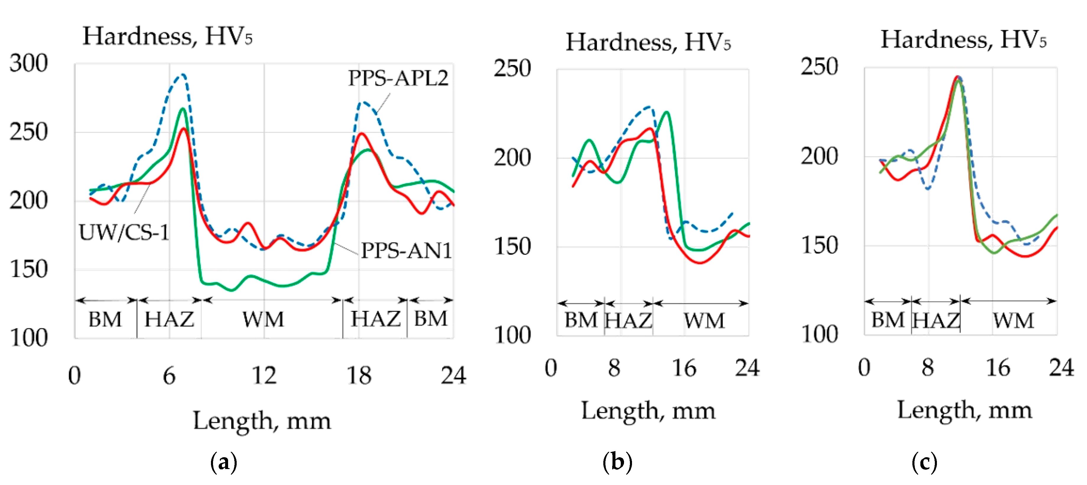
| UW/CS-1 electrode | 440–468 | 498–545 | 6–12 | 68–89 | 165–203 |
| PPS-AN1 flux-cored wire | 323–336 | 371–458 | 2–11.2 | 62–73 | 135–212 |
| PPS-APL2 flux-cored wire | 330–356 | 433–462 | 4–12.6 | 67–98 | 162–200 |
Publisher’s Note: MDPI stays neutral with regard to jurisdictional claims in published maps and institutional affiliations. |
© 2020 by the authors. Licensee MDPI, Basel, Switzerland. This article is an open access article distributed under the terms and conditions of the Creative Commons Attribution (CC BY) license (http://creativecommons.org/licenses/by/4.0/).
Share and Cite
Parshin, S.G.; Levchenko, A.M.; Maystro, A.S. Metallurgical Model of Diffusible Hydrogen and Non-Metallic Slag Inclusions in Underwater Wet Welding of High-Strength Steel. Metals 2020, 10, 1498. https://doi.org/10.3390/met10111498
Parshin SG, Levchenko AM, Maystro AS. Metallurgical Model of Diffusible Hydrogen and Non-Metallic Slag Inclusions in Underwater Wet Welding of High-Strength Steel. Metals. 2020; 10(11):1498. https://doi.org/10.3390/met10111498
Chicago/Turabian StyleParshin, Sergey G., Alexey M. Levchenko, and Alexey S. Maystro. 2020. "Metallurgical Model of Diffusible Hydrogen and Non-Metallic Slag Inclusions in Underwater Wet Welding of High-Strength Steel" Metals 10, no. 11: 1498. https://doi.org/10.3390/met10111498