Article

Synthesis and Electrochemical Characterisation of Magnetite Coatings on Ti6Al4V-ELI

by
Adriana Montiel
1,
Edgar Onofre Bustamante
1,* and
María Lorenza Escudero
2,*
1
Centro de Investigación en Ciencia Aplicada y Tecnología Avanzada del Instituto Politécnico Nacional Unidad Altamira, Km. 14.5 Carretera Tampico-Puerto Industrial Altamira, Altamira 89600, Tamaulipas, Mexico
2
Centro Nacional de Investigaciones Metalúrgicas. Av. De Gregorio del Amo, 8, 28040 Madrid, Spain
*
Authors to whom correspondence should be addressed.
Metals 2020, 10(12), 1640; https://doi.org/10.3390/met10121640
Submission received: 29 October 2020 / Revised: 24 November 2020 / Accepted: 26 November 2020 / Published: 5 December 2020
(This article belongs to the Special Issue Surface Chemistry and Corrosion of Light Alloys)

Abstract

:
Titanium alloys have been widely employed in implant materials owing to their biocompatibility. The primary limitation of these materials is their poor performance in applications involving surfaces in mutual contact and under load or relative motion because of their low wear resistance. The aim of this work is to synthesis magnetite coatings on the Ti6Al4V-ELI alloy surface to increase corrosion resistance and to evaluate its electrochemical behaviour. The coatings were obtained using potentiostatic pulse-assisted coprecipitation (PP-CP) on a Ti6Al4V-ELI substrate. The preliminary X-Ray Diffraction (XRD) results indicate the presence of the magnetite coating with 8–10 nm crystal sizes, determined for the (311) plane. Using X-ray photoelectron spectroscopy (XPS), the presence of the magnetite phase on the titanium alloy was observed. Magnetite coating was homogeneous over the full surface and increased the roughness with respect to the substrate. For the corrosion potential behaviour, the Ti6Al4V-ELI showed a modified Ecorr that was less active from the presence of the magnetite coating, and the impedance values were higher than the reference samples without coating. From the polarization curves, the current density of the sample with magnetite was smaller than of bare titanium.

1. Introduction

The increase in hope and quality of life in patients who have undergone total hip and knee replacements is of great importance worldwide. Today, the various activities that people undertake place them at risk and expose them to various types of trauma, for example, from a car accident or sports practise (the most common incidents). Post-mortem studies of patients who have been prosthetic carriers for total hip and knee replacements show particle accumulation in various organs. These particles are released as a result of the corrosion-wear processes of the prostheses and compromise biocompatibility and biofunctionality, causing irreversible damage to the human body [1,2,3,4,5].
In the medical field, titanium is commonly used in joint replacements and as a component of stents. Recently, new studies have been performed with the Ti6Al4V-ELI alloy, which has a lower oxygen content than that in traditional Ti6Al4V; this provides the material with better mechanical performance and greater corrosion resistance, including improved ductility, fracture resistance, resistance to stress corrosion, and resistance to crack growth [6,7,8]. However, it still has a low wear resistance, which provides a wide area of study by superficially modifying the material with the aim of increasing its resistance to fretting corrosion. Wear is one of the most serious problems with contacting surfaces in relative motion, such as hip and knee joints, hydraulic parts, and others.
During the last decade, research on new materials and surface coatings has increased rapidly. One example is the emergence of a new scientific field called surface engineering, which aims to improve the surface behaviour of structural materials to increase the performance and useful life. In terms of corrosion, surface engineering includes the application of innovative technologies to obtain the desired properties through various synthesis methods, such as electrodeposition, chemical deposition, hot dipping, chemical conversion treatments, chemical coprecipitation, magnetron sputtering, physical vapour deposition (PVD), chemical vapour deposition (CVD), sol-gel, and solid-state reactions.
The electrochemical deposition is a process that occurs at moderate temperatures. The deposition process requires an electrolytic cell with an anode, a cathode, and an electrolytic conductor. The electrochemical reactions take place around a cathode (for example a metallic implant) where cations from electrolytic solution are deposited and reduced. The cations can be Ca2+, Fe2+ and Fe3+ to obtain hydroxyapatite, HAp or magnetite respectively. The anode currently is a wire of platinum. Both the anode and cathode are connected to a current generator and a potentiostate.
Magnetite is a common iron oxide that exhibits outstanding physicochemical properties due to the presence of Fe (II) and Fe (III) in its structure, which has a large surface area. This large surface area of magnetite may provide higher availability of binding sites for osteoblast adhesion and thus stimulate cell spread and proliferation, as in the case of a mesoporous hydroxyapatite [9,10].
Its potential field of application is large owing to its properties [11,12,13,14,15,16,17,18,19,20]. Magnetite nanoparticles (MNPs) have been used for biomedical applications, such as biodetection, cell tracking, tissue engineering, magnetic resonance imaging (MRI)/multimodal optical imaging, targeted drug administration, and therapeutic hyperthermic cancer treatment [19,21,22]. Magnetite films have wide applications in magneto-resistive and magneto-optical systems as well as Hall-effect sensors, among others. In addition, magnetite is used as an electrodeposition coating to restore worn parts, and various applications, such as hard wear-resistant coatings, biodegradable stents, and electromagnetic recording devices, have been explored [23].
Magnetite is an inorganic nanomaterial frequently used in both clinical and research applications. It is used due to their good biocompatibility [24], its intrinsic antimicrobial properties, as well as its quality to act in synergy with other substances such as antibiotics or natural products [25,26,27].
Also, antimicrobial nanostructured coating based on Fe3O4 and other compounds like patchouli essential oil has been studied. The results of this research show the antimicrobial activity and the good biocompatibility of the obtained coating [28].
Others researchers [29,30] have investigated the incorporation of magnetite to hydroxyapatite coating deposited on Ti6Al4V metallic alloy. The bioactivity has been increased due to the rate of formation of bone-like apatite compared to bare hydroxyapatite coating because the wettability of the composite coating has improved. In corrosion studies, the HAp-Fe3O4 composite showed higher corrosion resistance than Hap-coated material on Ti6Al4V. The higher content of Fe3O4 with HAp produced a uniform and adherent layer on the substrate with a better corrosion behavior.
The magnetite—as a coating or as nanoparticles—can be used in a large variety of medical technological applications. The current work research goes in this direction.
The main aim is the synthesis of magnetite on a Ti6Al4V-ELI alloy using a novel potentiostatic pulse-assisted coprecipitation (PP-CP) method. Additionally, the physicochemical, topographical, and electrochemical characterization of magnetite coating on a Ti6Al4V-ELI alloy is performed.

2. Materials and Methods

2.1. Magnetite Coating Synthesis

The substrate consisted of a Ti6Al4V-ELI alloy 12 mm in diameter and 3 mm in thickness, with a nominal chemical composition (wt%): 6.0 Al, 4.0 V, 0.1 Fe, 0.1 O, 0.03C, 0.01 N, <0.003 H, balance Ti, with a surface finish obtained using a 1200 grit silicon carbide sheet. The magnetite coatings were synthesised using the chemical coprecipitation method by applying an external polarisation of 1 V for 30 min at 54 ± 1 °C. Also, 304 stainless steel was used as the anode, and Ti6Al4V-ELI was used as the cathode. The solution containing Fe2+ and Fe3+ cations consisted of FeCl3∙6H2O (2 × 10⁻³ M) + FeSO4∙7H2O (10−3 M). As an oxidant, 10 M NaOH was used. Additionally, the coating formation was observed as a function of time by monitoring the potential behaviour.
Finally, electrochemical cleaning was performed in a 1% NaCl electrolyte by applying a potential of 1.5 V for 15 min.

2.2. Surface and Structural Characterisation

The different phases on the surface-coated samples were identified using X-ray diffraction (XRD) patterns obtained from a Bruker D8 Advance-9 using Cu Kα radiation (d = 1.5406 Å in grazing incidence configuration). The applied voltage was 35 kV, and the filament current was 25 mA. Angular scanning was performed from 20° to 70° with a step size of 0.02° and counting time of 1 deg/s. Additionally, X-ray photoelectron spectroscopy (XPS) analyses were performed using a Thermo Scientific K-alpha X-ray photoelectron spectrometer equipped with a monochromatic Al K-α X-ray source (1487 eV). The measurement spot size was 400 μm, and a dual-beam flood gun (DFG) based on simultaneous very low-energy electrons (~0.2 eV) and low kinetic energy Ar+ ions (5.0 ± 0.2 eV). A base pressure of 1 × 10⁻⁷ Pa was maintained in the analytical chamber without a DFG, which rose to 1 × 10⁻⁵ Pa when the DFG was turned on. The X-ray beam intensity was varied by changing the electron current striking the anode (3 and 6 mA), while the acceleration voltage was maintained at 12 kV. Survey spectra were collected at a pass energy of 200 eV, while high-resolution spectra were recorded at 40 and 60 eV.
Photoelectrons were detected with a 180° double-focusing hemispherical analyser operated in the constant analyser energy (CAE) mode. Calibration was performed using the binding energy of gold (Au4f7/2 at 84.00 eV) and copper (Cu2p3/2 at 933.67 eV).
All samples were analysed by an atomic force microscope (AFM) in a Bioscope Catalyst (Bruker, Santa Barbara, CA, USA) equipped with a link system electron microprobe in tapping mode. The samples were evaluated using an area of 3 μm × 3 μm. In addition, the average roughness (Ra) and root mean square roughness (Rq) of the coatings and the metallic substrate were obtained.
Finally, the ellipsometric measurements were performed using the Horiba CTRL-UNIT ellipsometer. The measurements were performed with the sample 45° with respect to the plane of incidence at 633 nm. The centre of the ellipsometer light spot was always positioned in the middle and edge of the samples. The first layer corresponds to the Ti6Al4V-ELI substrate. The second is the interface between the titanium substrate and the magnetite coating and its thickness is defined as L1. L2 is the interface of the magnetite coating and air. The thickness of the magnetite coating measured is taken as the average.

2.3. Electrochemical Characterization

Electrochemical evaluation was performed with a potentiostat-galvanostat Gill AC using Hank’s solution as the electrolyte. A conventional three-electrode cell was used, with the magnetite-coated titanium samples as the working electrode, a 304 stainless steel plate as the auxiliary electrode, and a saturated calomel electrode (ECS) as the reference electrode. The corrosion potential (Ecorr) was measured as a function of time for 1800 s. Electrochemical impedance spectroscopy (EIS) was performed at an amplitude of 10 mV and in a frequency range of 100,000 to 0.01 Hz with 10 points per frequency decade. Finally, cyclic polarisation curves were obtained using a potential scan of −100 to +1000 mV with respect to the Ecorr at a scanning speed of 0.5 mV/s.

3. Results and Discussion

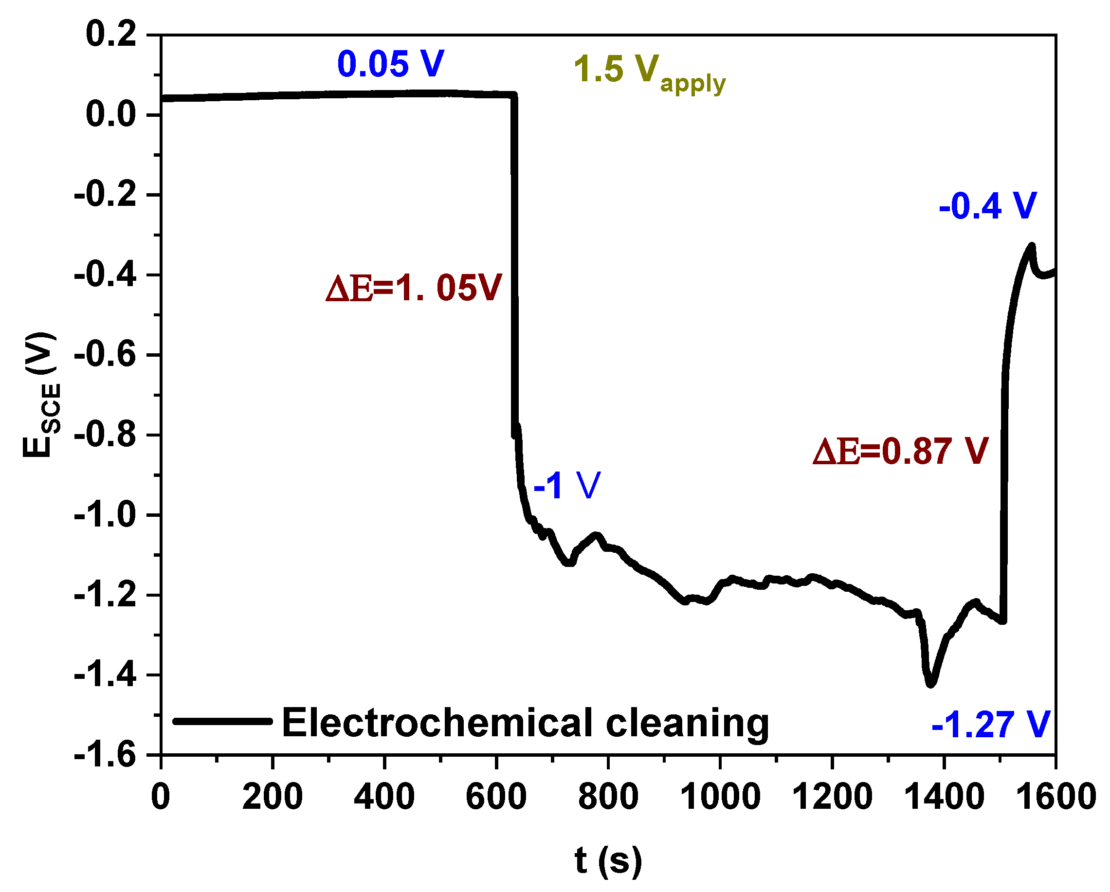
3.1. Magnetite Coatings Synthesis and Corrosion Potential Result

Figure 1 shows the sequential synthesis scheme used to obtain the magnetite coatings by PP-CP, where the ferrous (Fe2+) and ferric (Fe3+) ions present in the medium did not have any arrangement Figure 1a. However, when the potentiostatic pulse was applied, the positively charged ions shifted towards the cathode (Ti6Al4V-ELI), where they were reduced to form a metallic iron film (Fe0) (Figure 1b), while the negatively charged ions concentrated near the anode (stainless steel), where they were oxidised to form sulphate ions and chlorine gas (perchlorate), according to the reactions (1–4).
Cathodic reactions
Fe3+ + e → Fe2+
Fe2+ + 2e → Fe0
Anodic reactions
Cl → ClO4
2Cl → Cl2 +2e
The polarisation allowed the ferrous (Fe2+) and ferric (Fe3+) ions near the cathode to be reduced on the Ti6Al4V-ELI, forming a metallic iron film (Figure 1b) in such a way that when the oxidising agent (NaOH) was added, the metallic iron film was oxidised, allowing the subsequent reaction to begin with the precipitated Fe(OH)2. When metallic ions are in contact with a sodium hydroxide solution, it is well known that magnetite formation begins (Figure 1c,d) with the oxidation of Fe(OH)+ in water [31]. These results are in agreement with those reported by Roonasi and Holmgren regarding magnetite formation [32,33].
Fe(OH)2 (solid) ↔ [Fe(OH)]+(aq) + OH
The subsequent step is the oxidation of [Fe(OH)]+(aq), as shown in the following reaction:
2[Fe(OH)]+(aq) + ½ O2 + H+ ↔ [Fe2(OH)3]+3
However, the intermediate species [Fe2(OH)3]+3(aq) can be combined with another [Fe(OH)]+(aq) species to form Fe3O(OH)42+(aq), which has the same Fe (II)/Fe (III) ratio as the magnetite Equation (7).
[Fe2(OH)3]+3(aq) + [Fe(OH)]+(aq) + 2OH ↔ Fe3O(OH)42+(aq) + H2O
Finally, at a high oxidation rate or low pH value, it will further oxidise to goethite (or other Fe (III) oxyhydroxides). However, if the concentration of dissolved oxygen in the water is low and the pH is high, slow oxidation occurs, and dehydroxylation occurs prior to oxidation, such that the intermediate species transforms into crystalline magnetite according to the following reaction:
Fe3O(OH)42+(aq) + 2OH ↔ Fe3O4(solid) + 3H2O
The results obtained in this study suggest that reaction (1) has a significant effect on the fractioning of iron [34], and the applied voltage allows the reduction of cations to Fe0 on the titanium surface, producing the magnetite film (Fe3O4) preferentially. Nevertheless, the powerful reaction produced oxidation in all locations where Fe2+ and Fe3+ ions would have been reduced, producing MNPs inside the solution, which precipitated at the bottom of the electrochemical cell and, due to the magnetic properties of these nanoparticles, adhered even to the magnetic stirrer, as can be seen in Figure 4. Therefore, the magnetite obtained in the solution was produced from the following reaction [32]:
Fe2+ + 2Fe3+ + 8OH ↔ Fe3O4 + 4H2O
Furthermore, using the potential behaviour, the magnetite coating formation was supervised in situ. Figure 2 shows the initial potential behaviour (first 600 s) of the sample in the FeCl3∙6H2O (2 × 10⁻³ M) + FeSO4∙7H2O (10−3 M) solution. Initially, the +0.36 V value corresponds to the passivating film composed of mainly in TiO2 and probably with a contribution from the Al203 layer [35]. In Figure 2, it can be seen that for 500 s this potential (+0.36 V) remained stable, then it was applied with −1 V and the TiAlV-ELI electrode achieved −0.41 V value potential as a consequence of the formation of iron on the electrode according to reactions (1) and (2). The difference between the applied polarisation and the measured potential was due to the presence of different resistances in the system as well as the droop potential. Green bars represent time intervals in which the temperature was stable (Figure 2); the vertical coloured lines symbolise the temperature modifications, and the horizontal grey line (Figure 2) shows the fluctuation in the potential as a function of time. The potential oscillates around E ≈ −0.41 V, and although the temperature increased over time, the potential did not show a significant modification for this synthesis period. However, at 54 °C, 11447 s, and E ≈ −0.57 V, 10 M NaOH was added, causing the metallic iron film to oxidise and preferentially produce the magnetite coating (Fe3O4) (Figure 1d). Nevertheless, the powerful reaction produced MNPs inside the solution, which precipitated at the bottom of the electrochemical cell. The formation of the magnetite coating caused a potential shift towards negative values (E ≈ −1.3 V for a ΔE ≈ 0.73 V). A stable potential was not observed as it trended to more positive values (E ≈ −1.23 V); however, after approximately 17 min, the potential decreased to a stable value (E ≈ −1.43 V), resulting in a total potential difference of ΔE ≈ 0.93 V.
After synthesis, electrochemical cleaning was performed to eliminate non-adherent oxides, such as haematite. The potential behaviour was also monitored during electrochemical cleaning. Figure 3 shows stable behaviour for 600 s (E ≈ +0.05 V). After applying a polarisation of 1.5 V, it was observed that only 1.05 V arrived in the system; this behaviour is due to the droop potential. However, after cleaning, the polarisation was suspended, and a shift of E ≈ −0.4 V was measured, which is associated with the elimination of non-adherent oxides, producing a potential closer to that of the bare substrate.

3.2. Surface and Structural Results

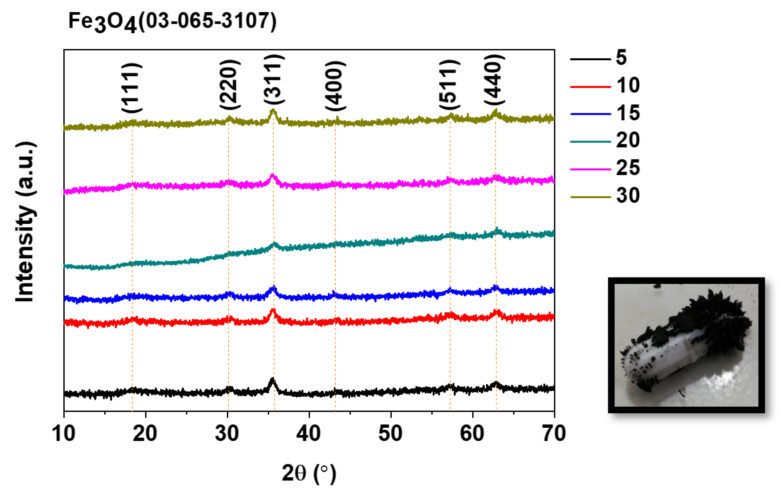
3.2.1. X-ray Diffraction (XRD)

Figure 4 presents the XRD results for the samples treated for various times during the magnetite film synthesis. All the obtained films presented diffraction signals corresponding to the (111), (220), (311), (400), (511), and (440) planes of magnetite (PDF no.: 03-065-3107), at angles of 18.2°, 30.2°, 35.5°, 43.03°, 57.18°, and 62.8°, respectively. However, the signal at 35.5° corresponding to the (311) plane is the characteristic magnetite signal according to References [36,37,38]. Important evidence of the presence of magnetite in the synthesis is that particles attached to the magnetic stirrer surface owing to the magnetic properties of these particles. In addition, an analysis of the particle size determined using XRD was performed using the Scherrer equation, where it was determined that its size oscillated around 8–10 nm for the (311) plane (Table 1).
D = 0.9 λ / β cos ( θ )

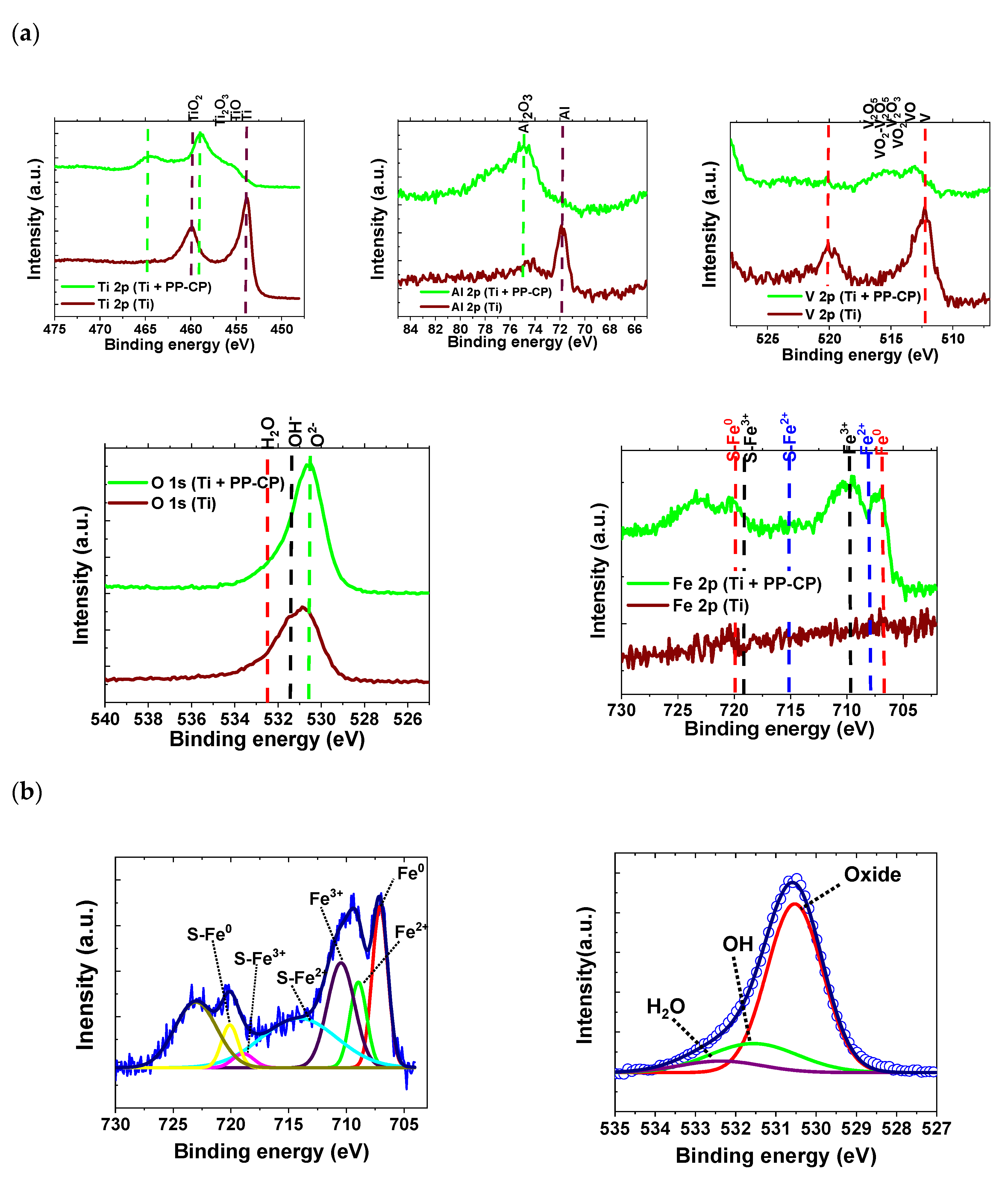
3.2.2. X-ray Photoelectron Spectroscopy (XPS)

Surface characterisation of the Ti alloy and the magnetite coating deposited on the titanium was performed using X-ray photoelectron spectroscopy (XPS) to study the oxidation processes. Figure 5a shows high-resolution spectra with peaks corresponding to Ti 2p (the main component) with a binding energy around 454–454.2 eV [39,40], Al 2p (71.0–71.5 eV) [29,30], V 2p (512.0–512.2 eV) [39], and O 1s (530.1–530.2 eV) [40]. It is important to note that the uncoated sample showed binding energies of each alloying element in a metallic state. After the PP-CP treatment, the signals corresponding to the alloying elements were in their oxidised forms, indicating that the passive film formed during the first seconds of the treatment once the alloy was in contact with the cation solution (Fe2+ and Fe3+); a passive film of titanium, aluminium, and vanadium oxides was formed, which contained the following oxides with corresponding binding energies: TiO2 (459.0–459.2 eV) [39,40], Al2O3 (74.2–74.8 eV) [39,40], VO (513.5 eV), V2O3 (515 eV), and VO2 (514.4 eV) [39]. In the spectrum corresponding to O 1s, signals corresponding to oxides (530.1–530.2 eV), OH- (531.4–531.5 eV), and H2O (532.5–532.7 eV) [39,40,41] were observed; thus, it can be clearly seen that for both samples, the greater contribution comes from the oxide. Figure 5 shows the high-resolution spectrum for Fe 2p, in which the peak at 706.75 eV is the characteristic bond energy of Fe0 [42]; the peaks centred around 708 and 709.7 eV are attributed to the Fe (II)-O and Fe (III)-O bonds in the magnetite [43] and were only observed for the sample that underwent the PP-PC treatment. In addition, satellite peaks for iron were present, including S-Fe0 (714 eV), S-Fe2+ (715 and 714 eV), and S-Fe3+ (719 and 720 eV) [41,44,45].
Figure 5b presents the normalised high-resolution Fe 2p and O 1s spectra with background correction for the sample that underwent the Ti + PP-PC treatment, and Table 2 presents the corresponding fit parameters, with the values of the central peaks, area, and full width at half maximum (FWHM) corresponding to the evaluated sample. According to the literature, the presence of the magnetite phase on the titanium alloy was observed, and the area for Fe3+ was 1.36 and for Fe2+ was 0.68, which corresponds to the 2:1 ratio present in the magnetite. Additionally, the presence of Fe0 shows that not all the cations present on titanium were converted to magnetite as a consequence of the potential applied throughout the synthesis. There was a competition between the reduction of cations on titanium and the oxidation of Fe0 until magnetite was formed, which involved having a coating with a greater thickness and obtaining magnetite in a controlled manner as a consequence of polarisation. In addition, the nature of the magnetite coating on titanium and that obtained within the solution present different routes because the coating is presented in an orderly manner, step by step with a low thickness, while the particles within the solution occur abruptly during the coprecipitation process. Finally, for O 1s, the parameters are shown in Table 2, which indicate that most of the oxygen was present as O2 (with an area of 1.47) and not as OH or H2O (0.40 and 0.146, respectively).

3.2.3. Atomic Force Microscope (AFM)

Figure 6 shows the AFM results. The samples with the magnetite coating had an increased roughness as a consequence of their presence; in addition, magnetite is a highly porous oxide [46,47,48,49,50], even at nanometric scales. This increased roughness could be associated with higher surfaces where the film is present and lower surfaces where pores in the magnetite coating are retained. Moreover, it was determined that the magnetite coating was homogeneous over the full substrate surface and increased the average roughness (Ra) and the root mean square average roughness (Rq) from 10.5 and 13.7 nm to 31.5 and 38 nm, respectively.
The porosity of nanostructured magnetite coatings could be defects that can facilitate aggressive ion access to the bare substrate and increase oxidation-reduction reactions. Nevertheless, as a consequence of the oxidation-reduction reactions, oxides formed in the magnetite pores (mainly of titanium), which could close the porosity to provide thermodynamic and kinetic stability to the magnetite coating and increase the corrosion resistance of the substrate temporarily.

3.2.4. Ellipsometry Results

The approximate thickness of the magnetite coating is given in Table 3.
The ellipsometry technique is used to measure thicknesses in smooth surfaces. Magnetite-coated samples have discontinuities, and this causes interferences when light contacts the coatings. These interferences complicate the mathematical adjustment to obtain the exact value of the thicknesses. That is why the deviation is high in the case of magnetite, as observed in Table 3. However, given the high number of measurements of the thickness in different samples and areas (middle and edges of the surface), it can be stated that the order of the thickness of the magnetite is about 326 nm.

3.3. Electrochemical Results

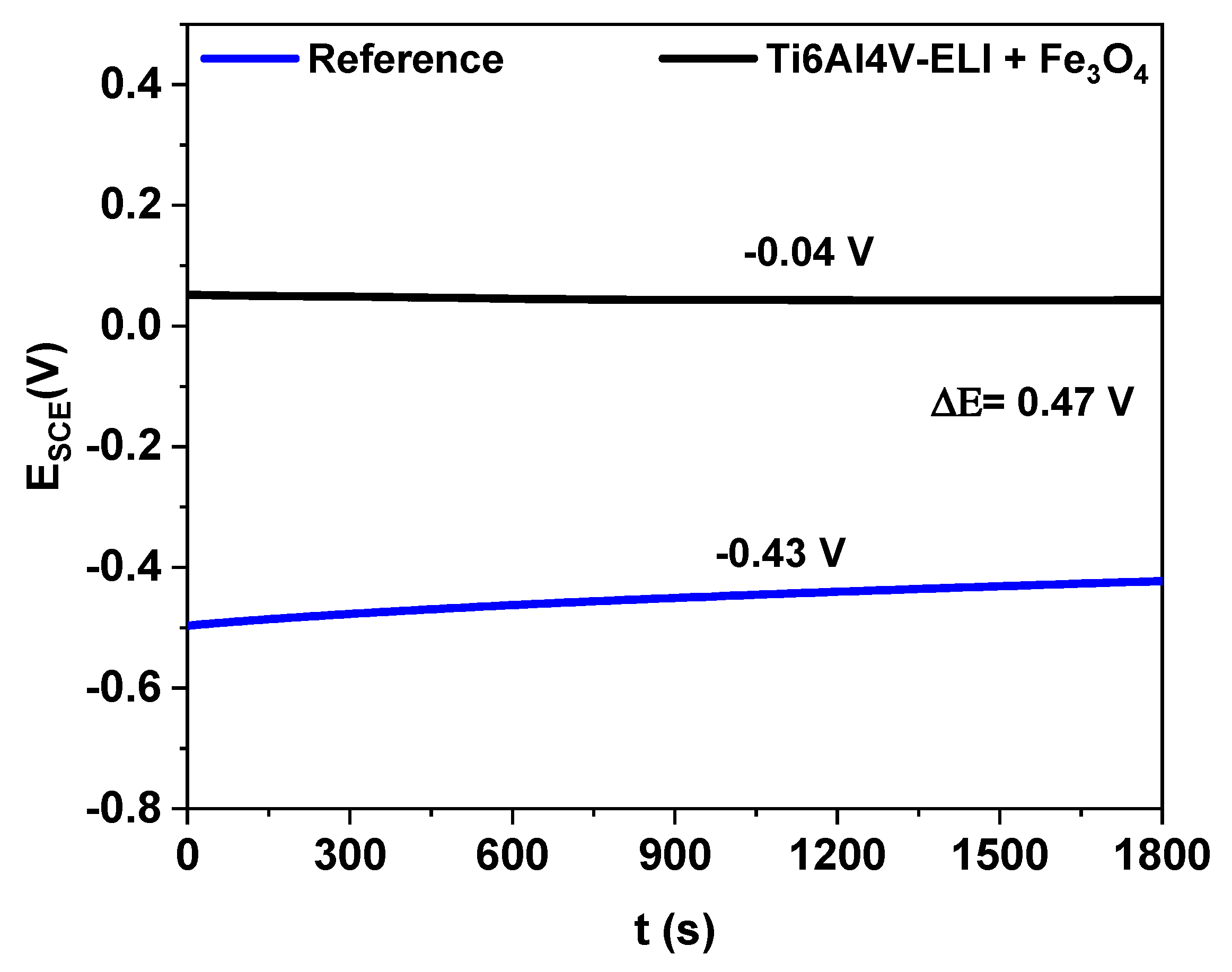
3.3.1. Corrosion Potential

The corrosion potential provides thermodynamic information about the materials under study, in this case bare Ti6Al4V-ELI and that with a magnetite coating (referred to as the reference and Ti6Al4V-ELI + Fe3O4, respectively). In Figure 7, an Ecorr = −0.43 V is shown for reference, which displays a shift towards positive or noble values ≈ once it is coated with Fe3O4 (Ecorr = +0.04 V with a ΔEcorr = 0.47 V). This behaviour is attributable to the presence of the magnetite coating on the titanium substrate, which reduced the surface activity and produced a shift towards positive or noble values. It is important to mention that the corrosion potential did not show significant variations during the evaluation time, demonstrating the thermodynamic stability of the coating. This potential (Ecorr = +0.04 V) is even more positive than those reported by Fattah-alhosseini et al., who obtained a magnetite coating on carbon steel by hydrothermal synthesis that showed a corrosion potential of approximately −0.2 at room temperature and −0.4 V at higher temperature conditions [46].

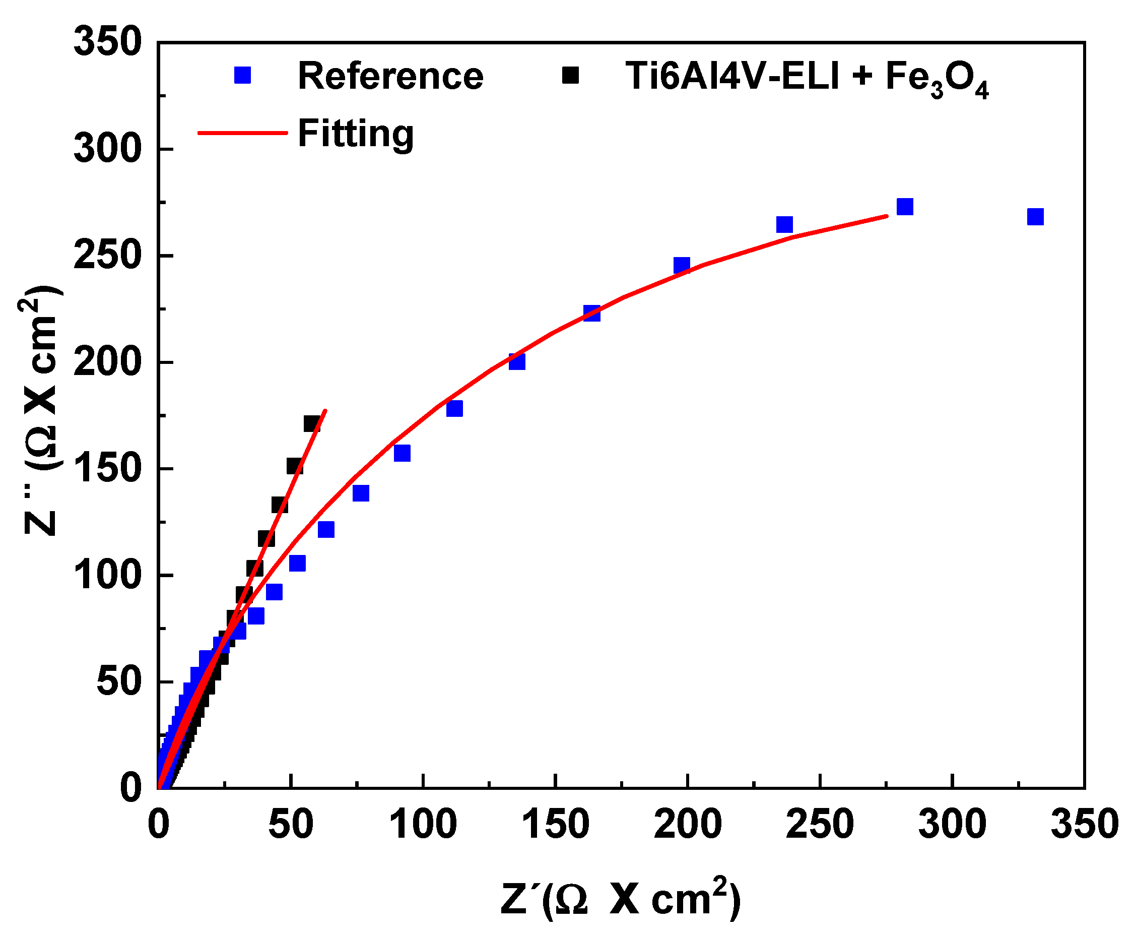
3.3.2. Electrochemical Impedance Spectroscopy (EIS)

One of the most commonly used techniques to determine the corrosion rate is EIS. This technique can discern the resistive, capacitive, and inductive contributions of the substrate, coating, and electrolyte. The results are presented in Figure 8. The Nyquist diagram shows the highest total impedance values for the coated sample (Ti6Al4V-ELI + Fe3O4) and does not show a well-defined time constant (capacitive behaviour), which is associated with the magnetite coating on the titanium surface. This capacitive behaviour is shown in the Nyquist diagram as a line very close to the imaginary impedance, which is primarily because the magnetite coating homogeneously covers the Ti6Al4V surface, acting as a dielectric; this does not allow electrons to flow between the electrolyte and the Ti6Al4V surface, accumulating charge at the coating-substrate interface. In contrast, for bare titanium (reference), the Nyquist diagram shows a well-defined time constant (semicircle), which is associated with redox reactions in contact with Hank’s solution.
The simulation results are presented in Table 4. In general, they have two resistors and a constant phase element. At high frequencies, for the coated sample, the total resistance is related to the resistance the electrolyte (Rs) and the resistance of the film (RFe3O4), together with the constant phase element (CPEFe3O4) associated with the magnetite coating. For the reference sample, the total resistance is related to the charge transfer resistance (Rtc) and the constant phase element (CPEct). Additionally, Table 4 shows the equivalent circuit that was used to simulate the electrochemical behaviour of the coated sample and bare titanium.
The CPE is empirical, which hinders the physical interpretation of the results. The impedance of the CPE is given by the following function [51]:
Z(ω) = 1/Y0 (jω)n
where j is the imaginary number (j2 = −1), Y0 is the CPE constant (‘S’), ω is the angular frequency of the applied signal (rads−1), n = α/(π/2) is the power factor of the CPE, and ω is the phase angle of the CPE. The factor n is an empirically adjustable parameter, normally between 0.5 and 1. This CPE describes the behaviour of an ideal capacitor when n is equal to unity. In the other cases, for 0.5 <n <1, the CPE describes a distribution of dielectric relaxation times in the frequency domain. Many authors associate the behaviour of the CPE with the fractal nature or roughness of the electrode surface [52].
In our adjustment, ndl and nFe3O4 take values of 0.84 and 0.72, respectively.
The value of nFe3O4 indicates that the coating did not behave as an ideal insulator, which means that the coating resistance was not infinite, as shown by the obtained coating resistance value (1020 Ω·cm2). In the case of magnetite coatings, it was reported that magnetite is highly porous; therefore, these responses are associated with this porosity [53,54,55]. Additionally, Table 4 shows that the Fe3O4 coating resistance was higher than that reported by Suresh et al., who demonstrated magnetite formation on carbon steel with two time constants. The first is associated with the oxidized electrolyte interaction (with a resistance of 850 Ω), and the second is associated with the metal oxide interface (with an impedance of 190,200 Ω) [50].

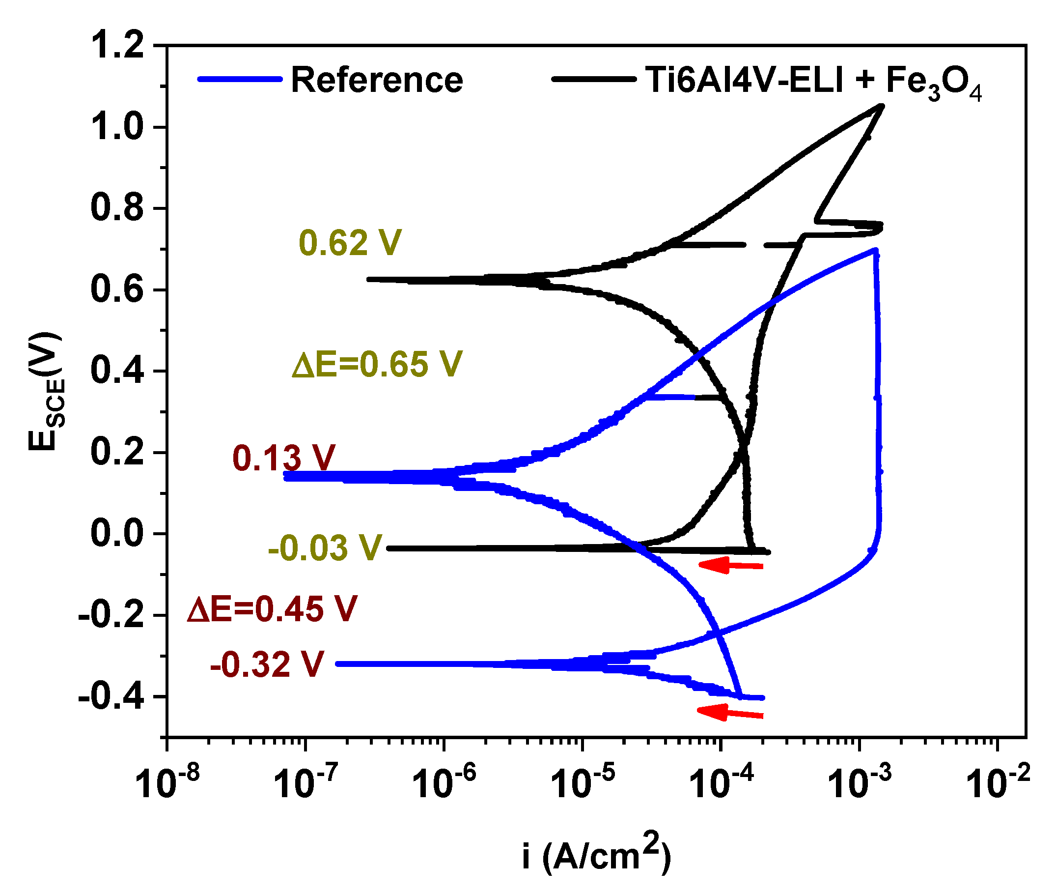
3.3.3. Cyclic Polarisation Curves

The materials used as prostheses, such as those proposed in this work, tend to form a passive layer that allows them to increase their useful life for a short period. However, this passive layer tends to break owing to pitting corrosion. Using polarisation curves, the controlling mechanisms can be observed as well as the pitting potential (Pp), which indicates the limit above which the formation and nucleation of pitting begins. The cyclic polarisation curves are shown in Figure 9. The corrosion potential (Ecorr) and the current density (icorr) are the two parameters that can help establish the difference between the behaviour of samples evaluated in the simulated physiological medium. For the reference material, the curve begins where indicated by the red arrow and continues until it reaches an Ecorr of −0.32 V. The icorr increases until the passivation zone, where the current density remains constant at −7.4 × 10⁻⁵ A/cm2. It is important to note that although it was polarised up to 1 V from the Ecorr, an increase in the Pp and/or the icorr did not occur. In addition, the return signal had a new Ecorr of 0.13 V. However, this potential is located within the passivation zone, which indicates that the film was stable; it also has a ΔEcorr ≈ 0.45 V and current density values that are lower than those of the initial curve.
For the Ti6Al4V-ELI + Fe3O4 curve, there is an Ecorr of −0.03 V and a subsequent Ecorr of 0.62 V. At potential around 0.75 V, there is an abrupt rise in the current density that drops almost instantly. This may be due to the existence of a metastable pitting in the magnetite-coating system. The return curve displays the same behaviour described above for the reference sample, but with a ΔEcorr ≈ 0.65 V (higher than that of the reference), which could indicate that the substrate was even more stable in the presence of the magnetite coating. The current density of the sample with magnetite (icorr = −7.4 × 10⁻³ A/cm2) was smaller than that of bare titanium, which translates according to Faraday’s laws into a lower corrosion rate. Finally, it has current density values close to those of the bare material; this behaviour could be associated with the intrinsic porosity of magnetite [46,47,48,49,50], which indicates that, at least temporarily, the magnetite coating provides a barrier that does not allow aggressive ions to access the substrate. However, these porosities could result in a localised and accelerated corrosion rate once the porosity allows aggressive ions to access the substrate and the corrosion reactions begin.

4. Conclusions

A novel potentiostatic pulse-assisted coprecipitation (PP-CP) method was used to synthesize magnetite coating on Ti6Al4V-ELI. The experimental conditions proposed in this work allowed us to produce a magnetite coating (Fe3O4) on the Ti6Al4V-ELI.
Using the XRD technique, it was possible to determine the characteristic magnetite signal which was mainly composed of nanoparticles of approximately 8–10 nm in size. Moreover, the XPS results demonstrated that the oxidation state of the iron coating on the titanium alloy corresponds to magnetite.
The AFM results demonstrated that the average roughness and the root mean square average roughness was increased as a consequence of the magnetite coating.
The electrochemical test demonstrated that the corrosion potential, Ecorr, of the coated magnetite samples has a more positive value than bare titanium and thus diminish the susceptibility to pitting corrosion. Additionally, using EIS, it was observed that the reference samples had a total impedance lower than the Ti6Al4V-ELI + Fe3O4 sample.

Author Contributions

Experimental data, writing—original draft preparation and review, A.M.; EIS simulation, electrochemical interpretation; writing—review and editing, E.O.B.; electrochemical interpretation and supervision, M.L.E.; funding acquisition: supervision, project administration and writing—review and editing, E.O.B. All authors have read and agreed to the published version of the manuscript.

Funding

This research was funded by Instituto Politécnico Nacional, Consejo Nacional de Ciencia y Tecnología (CONACyT), Proyecto SIP 20195816, and Centro Nacional de Investigaciones Metalúrgicas (CENIM-CSIC) Madrid, España supported this project.

Acknowledgments

Instituto Politécnico Nacional, Consejo Nacional de Ciencia y Tecnología (CONACyT), Proyecto SIP 20195816, and Centro Nacional de Investigaciones Metalúrgicas (CENIM-CSIC) Madrid, España supported this project.

Conflicts of Interest

The authors declare no conflict of interest.

References

  1. Bitar, D.; Parvizi, J. Biological response to prosthetic debris. World J. Orthop. 2015, 6, 172–189. [Google Scholar] [CrossRef] [PubMed]
  2. Geetha, M.; Singh, A.K.; Asokamani, R.; Gogia, A.K. Ti based biomaterials, the ultimate choice for orthopaedic Implants—A review. Prog. Mater. Sci. 2009, 54, 397–425. [Google Scholar] [CrossRef]
  3. Williams, D.F. On the mechanisms of biocompatibility. Biomaterials 2008, 29, 2941–2953. [Google Scholar] [CrossRef] [PubMed]
  4. Hallab, N.J.; Anderson, S.; Stafford, T.; Glant, T.; Jacobs, J.J. Lymphocyte responses in patients with total hip arthroplasty. J. Orthop. Res. 2005, 23, 384–391. [Google Scholar] [CrossRef] [PubMed]
  5. Sargeant, A.; Goswami, T. Hip implants: Paper V. Physiological effects. Mater. Des. 2006, 27, 287–307. [Google Scholar] [CrossRef]
  6. Vilardell, A.M.; Fredriksson, G.; Yadroitsev, I.; Krakhmalev, P. Fracture mechanisms in the as-built and stress-relieved laser powder bed fusion Ti6Al4V ELI alloy. Opt. Laser Technol. 2019, 109, 608–615. [Google Scholar] [CrossRef]
  7. Donachie, M.J. Titanium: A Technical Guide, 2nd ed.; ASM International: Materials Park, OH, USA, 2000. [Google Scholar]
  8. Moletsane, M.G.; Krakhmalev, P.; Kazantseva, N.; Du Plessis, A.; Yadroitsava, I.; Yadroitsev, I. Tensile Properties and microstructure of direct metal laser-sintered Ti6Al4V (ELI) alloy. S. Afr. J. Ind. Eng. 2016, 27, 110–121. [Google Scholar] [CrossRef] [Green Version]
  9. Anselme, K. Osteoblast adhesion on biomaterials. Biomaterials 2000, 21, 667–681. [Google Scholar] [CrossRef]
  10. Ye, X.; Cai, S.; Xu, G.; Dou, Y.; Hu, H.; Ye, X. Preparation and in vitro evaluation of mesoporous hydroxyapatite coated β-TCP porous scaffolds. Mater. Sci. Eng. C 2013, 33, 5001–5007. [Google Scholar] [CrossRef]
  11. Manilo, M.V.; Netreba, S.V.; Prokopenko, V.A.; Lebovka, N.I.; Barany, S. Overcharging of magnetite nanoparticles in electrolyte solutions. Colloids Surf. A Physicochem. Eng. Asp. 2016, 506, 291–297. [Google Scholar] [CrossRef]
  12. Abe, S.; Ohnuma, S. Magnetite thin films containing a small amount of Ge. Appl. Phys. Express 2008, 1, 111304. [Google Scholar] [CrossRef]
  13. Alexe, M.; Ziese, M.; Hesse, D.; Esquinazi, P.; Yamauchi, K.; Fukushima, T.; Picozzi, S.; Gösele, U. Ferroelectric switching in multiferroic magnetite (Fe3O4) thin films. Adv. Mater. 2009, 21, 4452–4455. [Google Scholar] [CrossRef]
  14. Furubayashi, T. Magnetite films prepared by reactive evaporation. J. Magn. Magn. Mater. 2004, 272, E781–E783. [Google Scholar] [CrossRef]
  15. Chang, H.S.W.; Chiou, C.-C.; Chen, Y.-W.; Sheen, S.R. Synthesis, Characterization, and Magnetic Properties of Fe3O4Thin Films Prepared via a Sol–Gel Method. J. Solid State Chem. 1997, 128, 87–92. [Google Scholar] [CrossRef]
  16. Tang, N.J.; Zhong, W.; Jiang, H.Y.; Wu, X.L.; Liu, W.; Du, Y. Nanostructured magnetite (Fe3O4) thin films prepared by sol–gel method. J. Magn. Magn. Mater. 2004, 282, 92–95. [Google Scholar] [CrossRef]
  17. Chiba, M.; Morio, K.; Koizumi, Y. Microstructure and magnetic properties of iron oxide thin films by solid reaction. J. Magn. Magn. Mater. 2002, 239, 457–460. [Google Scholar] [CrossRef]
  18. Utkan, G.G.; Sayar, F.; Batat, P.; Ide, S.; Kriechbaum, M.; Pişkin, E. Synthesis and characterization of nanomagnetite particles and their polymer coated forms. J. Colloid Interface Sci. 2011, 353, 372–379. [Google Scholar] [CrossRef]
  19. Coral, D.F.; Mera, J.A. Una guía para el estudio de nanopartículas magnéticas de óxidos de hierro con aplicaciones biomédicas. Parte I. Ing. Cienc. 2017, 25, 229–249. [Google Scholar] [CrossRef] [Green Version]
  20. Lemine, O.M.; Omri, K.; Zhang, B.; El Mir, L.; Sajieddine, M.; Alyamani, A.; Bououdina, M. Sol–gel synthesis of 8 nm magnetite (Fe3O4) nanoparticles and their magnetic properties. Superlattices Microstruct. 2012, 52, 793–799. [Google Scholar] [CrossRef]
  21. Gazeau, F.; Bacri, J.C.; Gendron, F.; Perzynski, R.; Raikher, Y.L.; Stepanov, V.I.; Dubois, E. Magnetic resonance of ferrite nanoparticles: Evidence of surface effects. J. Magn. Magn. Mater. 1998, 186, 175–187. [Google Scholar] [CrossRef]
  22. Gilchrist, R.K.; Medal, R.; Shorey, W.D.; Hanselman, R.C.; Parrott, J.C.; Taylor, C.B. Selective Inductive Heating of Lymph Nodes. Ann. Surg. 1957, 146, 596–606. [Google Scholar] [CrossRef] [PubMed]
  23. Kumar, D.V.; Prasad, M.J.N.V. Pulsed electrodeposition and hardness of microstructurally graded iron. Surf. Coat. Technol. 2018, 342, 121–128. [Google Scholar] [CrossRef]
  24. Grumezescu, A.M.; Holban, A.M.; Andronescu, E.; Mogoșanu, G.D.; Vasile, B.S.; Chifiriuc, M.C.; Lazăr, V.; Andrei, E.; Constantinescu, A.; Maniu, H. Anionic polymers and 10 nm Fe3O4@UA wound dressings support human foetal stem cells normal development and exhibit great antimicrobial properties. Int. J. Pharm. 2014, 463, 146–154. [Google Scholar] [CrossRef] [PubMed]
  25. Anghel, I.; Grumezescu, A.M.; Holban, A.-M.; Ficai, A.; Anghel, A.G.; Chifiriuc, M.C. Biohybrid Nanostructured Iron Oxide Nanoparticles and Satureja hortensis to Prevent Fungal Biofilm Development. Int. J. Mol. Sci. 2013, 14, 18110–18123. [Google Scholar] [CrossRef] [PubMed]
  26. Anghel, I.; Holban, A.M.; Grumezescu, A.M.; Andronescu, E.; Ficai, A.; Anghel, A.G.; Maganu, M.; Lazar, V.; Chifiriuc, M.-C. Modified wound dressing with phyto-nanostructured coating to prevent staphylococcal and pseudomonal biofilm development. Nanoscale Res. Lett. 2012, 7, 690. [Google Scholar] [CrossRef] [PubMed] [Green Version]
  27. Anghel, I.; Grumezescu, A.M.; Andronescu, E.; Anghel, A.G.; Ficai, A.; Saviuc, C.; Grumezescu, V.; Vasile, B.S.; Chifiriuc, M.C. Magnetite nanoparticles for functionalized textile dressing to prevent fungal biofilms development. Nanoscale Res. Lett. 2012, 7, 501. [Google Scholar] [CrossRef] [PubMed] [Green Version]
  28. Rădulescu, M.; Andronescu, E.; Holban, A.M.; Vasile, B.S.; Iordache, F.; Mogoantă, L.; Mogosanu, G.D.; Grumezescu, A.M.; Georgescu, M.; Chifiriuc, M.C. Antimicrobial Nanostructured Bioactive Coating Based on Fe3O4 and Patchouli Oil for Wound Dressing. Metals 2016, 6, 103. [Google Scholar] [CrossRef] [Green Version]
  29. Anjaneyulu, U.; Vijayalakshmi, U. Preparation and characterization of novel sol-gel derived hydroxyapatite/Fe3O4 composites coatings on Ti-6Al-4V for biomedical applications. Mater. Lett. 2017, 189, 118–121. [Google Scholar] [CrossRef]
  30. Jaafar, A.; Hecker, C.; Árki, P.; Joseph, Y. Sol-Gel Derived Hydroxyapatite Coatings for Titanium Implants: A Review. Bioengineering 2020, 7, 127. [Google Scholar] [CrossRef] [PubMed]
  31. Dufour, J.; Marrón, J.O.; Negro, C.; Latorre, R.; Formoso, A.; López-Mateos, F. Mechanism and kinetic control of the oxyprecipitation of sulphuric liquors from steel pickling. Chem. Eng. J. 1997, 68, 173–187. [Google Scholar] [CrossRef]
  32. Roonasi, P.; Holmgren, A. A study on the mechanism of magnetite formation based on iron isotope fractionation. In EPD Congress 2009: Proceedings of Sessions and Symposia Sponsored by the Extraction and Processing Division (EPD) of The Minerals, Metals & Materials Society (TMS); Held during TMS 2009 Annual Meeting & Exhibition, San Francisco, California, USA, February 15–19, 2009; Howard, S.M., Ed.; Minerals, Metals & Materials Society: Warrendale, PA, USA, 2009; pp. 829–836. [Google Scholar]
  33. Olowe, A.A.; Rezel, D.; Génin, J.M.R. Mechanism of formation of magnetite from ferrous hydroxide in aqueous corrosion processes. Hyperfine Interact. 1989, 46, 429–436. [Google Scholar] [CrossRef]
  34. Bullen, T.D.; White, A.F.; Childs, C.W.; Vivit, D.V.; Schulz, M.S. Demonstration of significant abiotic iron isotope fractionation in nature. Geology 2001, 29, 699–702. [Google Scholar] [CrossRef]
  35. Chávez-Díaz, M.P.; Escudero-Rincón, M.L.; Arce-Estrada, E.M.; Cabrera-Sierra, R. Osteoblast Cell Response on the Ti6Al4V Alloy Heat-Treated. Materials 2017, 10, 445. [Google Scholar] [CrossRef] [PubMed] [Green Version]
  36. Fu, R.; Wu, X.; Wang, X.; Ma, W.; Yuan, L.; Gao, L.; Huang, K.; Feng, S. Low-temperature hydrothermal fabrication of Fe3O4 nanostructured solar selective absorption films. Appl. Surf. Sci. 2018, 458, 629–637. [Google Scholar] [CrossRef]
  37. Wu, R.; Chen, X.-G.; Wei, J.Z.; Yang, Y.B.; Xia, Y.H.; Ma, X.B.; Yang, J.B. Interplay of shape and magnetocrystalline anisotropy in electrodeposited Fe3O4 films. J. Magn. Magn. Mater. 2014, 361, 107–111. [Google Scholar] [CrossRef]
  38. Patra, S.; Roy, E.; Madhuri, R.; Sharma, P.K. Fast and Selective Preconcentration of Europium from Wastewater and Coal Soil by Graphene Oxide/Silane@Fe3O4 Dendritic Nanostructure. Environ. Sci. Technol. 2015, 49, 6117–6126. [Google Scholar] [CrossRef]
  39. Milošev, I.; Metikoš-Huković, M.; Strehblow, H.-H. Passive film on orthopaedic TiAlV alloy formed in physiological solution investigated by X-ray photoelectron spectroscopy. Biomaterials 2000, 21, 2103–2113. [Google Scholar] [CrossRef]
  40. Milošev, I.; Kosec, T.; Strehblow, H.-H. XPS and EIS study of the passive film formed on orthopaedic Ti–6Al–7Nb alloy in Hank’s physiological solution. Electrochim. Acta 2008, 53, 3547–3558. [Google Scholar] [CrossRef]
  41. Lin, T.-C.; Seshadri, G.; Kelber, J.A. A consistent method for quantitative XPS peak analysis of thin oxide films on clean polycrystalline iron surfaces. Appl. Surf. Sci. 1997, 119, 83–92. [Google Scholar] [CrossRef]
  42. Moulder, J.F.; Stickle, W.F.; Sobol, P.E.; Bomben, K.D. Handbook of X-Ray Photoelectron Spectroscopy: A Reference Book of Standard Spectra for Identification and Interpretation of XPS Data; Physical Electronics: Eden Prairie, MN, USA, 1992. [Google Scholar]
  43. Grosvenor, A.P.; Kobe, B.A.; Biesinger, M.C.; McIntyre, N.S. Investigation of multiplet splitting of Fe 2p XPS spectra and bonding in iron compounds. Surf. Interface Anal. 2004, 36, 1564–1574. [Google Scholar] [CrossRef]
  44. Bronstein, L.M.; Huang, X.; Retrum, J.; Schmucker, A.; Pink, M.; Stein, B.D.; Dragnea, B. Influence of Iron Oleate Complex Structure on Iron Oxide Nanoparticle Formation. Chem. Mater. 2007, 19, 3624–3632. [Google Scholar] [CrossRef]
  45. Fujii, T.; De Groot, F.M.F.; Sawatzky, G.A.; Voogt, F.C.; Hibma, T.; Okada, K. In Situ XPS analysis of various iron oxide films grown by NO2-assisted molecular-beam epitaxy. Phys. Rev. B 1999, 59, 3195–3202. [Google Scholar] [CrossRef] [Green Version]
  46. Fattah-Alhosseini, A.; Khan, H.Y.; Heidarpour, A. Comparison of anti-corrosive properties between hot alkaline nitrate blackening and hydrothermal blackening routes. J. Alloys Compd. 2016, 676, 474–480. [Google Scholar] [CrossRef]
  47. Montiel-García, A.; Bustamante, E.O.; Escudero-Rincón, M.; De La Cruz-Terrazas, E.C.; Torres-Huerta, A.M. Study of reinforcing steel corrosion behaviour treated by bluing and cerium chemical conversion treatments, part I: Conventional electrochemical techniques. Cem. Concr. Compos. 2018, 90, 202–217. [Google Scholar] [CrossRef]
  48. Onofre-Bustamente, E.; Domínguez-Crespo, M.A.; Genesca, J.; Rodriger-Gómez, F. Characteristics of blueing as an alternative chemical conversion treatment on carbon steel. Surf. Coat. Technol. 2007, 201, 4666–4676. [Google Scholar] [CrossRef]
  49. Martin, M.; Caballero, A.; Feliu, S. Propiedades protectoras de la capa de pavon en relacion con las condiciones de su obtención. Rev. Metall. 1972, 8, 179–183. [Google Scholar]
  50. Suresh, S.; Rangarajan, S.; Bera, S.; Krishnan, R.; Amirthapandian, S.; Sivakumar, M.; Velmurugan, S. Evaluation of corrosion resistance of nano nickel ferrite and magnetite double layer coatings on carbon steel. Thin Solid Films 2018, 645, 77–86. [Google Scholar] [CrossRef]
  51. Boukamp, B.A. Manual AC-Immittance Data Analysis System ‘Equivalent Circuit’, (Version 4.50); University of Twente: Enschede, The Netherlands, 1993. [Google Scholar]
  52. McDonald, J.R. Impedance Spectroscopy: Emphasizing Solid Materials and Systems; John Willey & Sons: New York, NY, USA, 1987. [Google Scholar]
  53. Lorenz, W.; Mansfeld, F. Determination of corrosion rates by electrochemical DC and AC methods. Corros. Sci. 1981, 21, 647–672. [Google Scholar] [CrossRef]
  54. Mosiałek, M.; Mordarski, G.; Nowak, P.; Simka, W.; Nawrat, G.; Hanke, M.; Socha, R.P.; Michalska, J. Phosphate–permanganate conversion coatings on the AZ81 magnesium alloy: SEM, EIS and XPS studies. Surf. Coat. Technol. 2011, 206, 51–62. [Google Scholar] [CrossRef]
  55. Jamesh, M.; Kumar, S.; Narayanan, T.S.N.S. Corrosion behavior of commercially pure Mg and ZM21 Mg alloy in Ringer’s solution—Long term evaluation by EIS. Corros. Sci. 2011, 53, 645–654. [Google Scholar] [CrossRef]
Figure 1. Magnetite coatings synthesis.
Metals 10 01640 g001
Figure 2. Potential behaviour during magnetite coating formation.
Metals 10 01640 g002
Figure 3. The open-circuit potential (OCP) behaviour during electrochemical cleaning.
Metals 10 01640 g003
Figure 4. X-ray diffraction patterns of samples after various immersion times.
Metals 10 01640 g004
Figure 5. High-resolution XPS spectra of samples of Ti6Al4V-ELI and Ti + PP-CP (Fe3O4): (a) Ti 2p, Al 2p, V 2p, O 1s, and Fe 2p; and (b) normalised Fe 2p and O 1s of Ti + PP-CP (Fe3O4).
Metals 10 01640 g005
Figure 6. AFM micrographs of the Ti6Al4V-ELI as-received and Ti6Al4V-ELI + Fe3O4.
Metals 10 01640 g006
Figure 7. OCP behaviour as a function of time for the bare Ti6Al4V alloy and that coated with magnetite.
Metals 10 01640 g007
Figure 8. Electrochemical impedance spectroscopy (EIS) plots: Nyquist plot for the reference and Ti6Al4V-ELI + Fe3O4 samples.
Metals 10 01640 g008
Figure 9. Cyclic polarisation curves for the reference material and Ti6Al4V-ELI + Fe3O4.
Metals 10 01640 g009
Table 1. Particle sizes.
D (nm) t5D (nm) t10D (nm) t15D (nm) t20D (nm) t25D (nm) t30
35.59.869.648.77.989.179.4
Table 2. Curve fitting and parameters for the Fe 2p and O 1s XPS spectra of Fe3O4.
Fe 2pSatelliteSatellitesO 1s
-Fe0Fe2+Fe3+S-Fe0S-Fe2+S-Fe3+O2−OHH2O
BE707.08708.96710.46720.09714.10718.93530.53531.55532.36
FWHM1.581.712.781.697.712.161.632.582.37
Area1.190.681.360.331.780.141.470.400.146
Table 3. Thickness of the magnetite coating by optic ellipsometry.
Ti6Al4V-Eli + Fe3O4L1 (nm)L2 (nm)LT (nm)X2
Ti6Al4V-Eli + Fe3O4…middle209.871.4281.214.6
Ti6Al4V-Eli + Fe3O4…edge273.978.3372.216.8
Table 4. Contributions to the total resistance obtained using simulations.
ReferenceTi6Al4V-ELI+ Fe3O4
Ecorr (V)−0.430.04
Rs (Ω·cm2)44.3342.86
Rtc (Ω·cm2)711,070-
RFe3O4 (Ω·cm2)-1 × 10+20
CPE Fe3O4 (Ss)1.94 × 10⁻⁵-
CPE Fe3O4 (Ss)-479 × 10−5
ndl0.84-
nFe3O4-0.72
Equivalent
Circuit
Metals 10 01640 i001 Metals 10 01640 i002
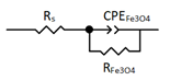
Publisher’s Note: MDPI stays neutral with regard to jurisdictional claims in published maps and institutional affiliations.

