Article

Modeling of the Effect of the Building Strategy on the Thermomechanical Response of Ti-6Al-4V Rectangular Parts Manufactured by Laser Directed Energy Deposition

1
International Center for Numerical Methods in Engineering (CIMNE), Universidad Politécnica de Cataluña (UPC), Edificio C1, Campus Norte, Gran Capitán s/n, 08034 Barcelona, Spain
2
Key Laboratory of Metal High Performance Additive Manufacturing and Innovative Design, MIIT China, Northwestern Polytechnical University, Youyixilu, Xi’an 710072, China
3
State Key Laboratory of Solidification Processing, Northwestern Polytechnical University, Youyixilu, Xi’an 710072, China
4
Department of Biomedical Engineering, City University of Hong Kong, Kowloon, Hong Kong SAR 999077, China
*
Authors to whom correspondence should be addressed.
Metals 2020, 10(12), 1643; https://doi.org/10.3390/met10121643
Submission received: 19 October 2020 / Revised: 24 November 2020 / Accepted: 4 December 2020 / Published: 6 December 2020
(This article belongs to the Special Issue Experimental and Numerical Simulation of Metallic Materials)

Abstract

:
Part warpage and residual stress are two of the main challenges for metal additive manufacturing (AM) as they result in lower geometric precision and poor mechanical properties of the products. This work investigates the effect of the building strategy on the heat transfer process and the evolution of the thermally induced mechanical variables in laser directed energy deposition (L-DED) in order to minimize residual stresses and deformations. A 3D finite element (FE) thermo-mechanical model is firstly calibrated through in-situ experiments of rectangular workpieces fabricated by L-DED technology, and, secondly, the coupled thermo-mechanical responses for different process parameters and scanning patterns are discussed in detail. On the calibration stage, the remarkable agreement is achieved between predicted results and experimental data. Regarding the modeling stage, the numerical results indicate that minimization of the part warpage is achieved by reducing the back speed and shortening the scanning lines during the building process. Both residual stress and deformation can be further reduced if preheating the baseplate is added before L-DED.

1. Introduction

Laser directed energy deposition (L-DED), one of the advanced additive manufacturing (AM) technologies, has been extensively applied in different industrial fields due to its high deposition efficiency and near-net-shape fabrication [1,2]. The metal powder is concentrically blown into the melting pool generated by a laser beam. During the L-DED process, the materials experience rapid heating and cooling cycles according to the particular building strategy, resulting in high-temperature gradients and plastic strains. After the depositing process is completed, undesired residual stress and distortion, detrimental to the geometric precision and mechanical properties of the fabricated part, remain in the built [3,4,5].
AM is a complex multi-physics and multi-scale process involving the interaction of the laser with the powder, heat transfer, and thermo-mechanical deformation. In order to obtain a deeper understanding of AM processes, both experiments and simulations are used. The ultimate good is to optimize the fabricating process, taking into account an extended amount of variables. Experimental procedures are expensive and time-consuming. Some parameters are also difficult to measure [6,7]. Instead, the finite element method (FEM) provides an efficient and feasible approach to simulate the AM process and to reveal the underlying mechanisms of defect formation within the fabricated workpieces by AM, such as part deformation and residual stresses [8,9,10,11,12]. Lindgren et al. [8] developed a thermo-mechanical finite element (FE) model based on computational welding mechanics (CWM) able to predict thermal stresses and distortions during AM. Denlinger et al. [9] simulated the thermo-mechanical responses of Ti-6Al-4V and Inconel® 625 during the L-DED process and found that compared with Inconel® 625, an allotropic phase transformation (PT) in Ti-6Al-4V triggers both significant stress relaxation and distortion mitigation. They achieved the best match between the calculated result and in-situ measurement with a PT temperature of 690 °C. However, Chen et al. [10] investigated the PT temperature of Ti-6Al-4V using variable temperature XRD measurements; they finally determined the temperature of 850 °C by comparing the numerical prediction via a developed model in ANSYS with the experimental work in Denlinger [9]. Moreover, Wang et al. [11] used compression experiments at 600 °C and 700 °C with in-situ neutron diffraction to study the stress relaxation of Ti-6Al-4V fabricated through conventional processing and AM. They found that stress is released sooner as the temperature increases, owing to the dislocation glide and climb. Hence, the level of stress relaxation of Ti-6Al-4V strongly depends on the building strategy in terms of the process parameters and scanning pattern because they significantly affect the thermal history in the L-DED process.
Several studies have demonstrated that process parameters (laser power, scan speed, build height, and substrate condition) greatly affect the development of distortions and residual stresses in AM processes [12,13,14,15,16,17,18,19]. LevkulichL et al. [14] investigated the effect of process parameters on stress evolution and deformations in selective laser melting (SLM) of Ti-6Al-4V; they found that the residual stress on the deposit surface is mitigated by increasing the laser power and reducing the scan speed. However, the numerical results presented in reference [15] showed that higher laser power or lower scan speed causes a higher level of residual stress at the single-track end of Ti-6Al-4V by SLM. Lu et al. [5] showed that preheating the substrate before AM greatly eliminates the residual stress and warpage in the built parts.
Wu et al. [16] compared the effect of three deposition patterns on the mechanical responses of Ti-6Al-4V and Inconel 718 rectangular components by wire-arc additive manufacturing (WAAM) experimentally and numerically. They found that printing with a short track length could reduce residual stresses and distortion for both alloys. Ramos et al. [17] proposed a geometric-based scanning strategy aimed at mitigating residual stresses and deformation, taking into consideration the reduction of heat concentration during SLM processes. Cheng et al. [18] numerically evaluated the effect of six different deposition strategies on deformation and residual stress of Inconel 718 parts by SLM. The result showed that residual stress fluctuations from all building patterns are less than 5% compared to the average value. In addition, Robinson et al. [19] found that using a chequerboard scanning path only achieves a little minimization on residual stresses.
Obviously, the influence of the building strategy on the mechanical behavior of AM built is not yet fully understood, especially for complex structures. This given, the goal of this paper is to explore the influence of the building strategy (process parameters and scanning path) on the stress relief and warpage development entailed by the L-DED process as complex rectangular Ti-6Al-4V workpieces are deposited. Firstly, in-situ experiments under three process parameters are carried out by an L-DED machine in order to calibrate a 3D coupled thermo-mechanical finite element (FE) model framework for AM. Next, the validated high-fidelity model is employed to study the thermo-mechanical behaviors for different building strategies.

2. Experimental and Modeling Methodology

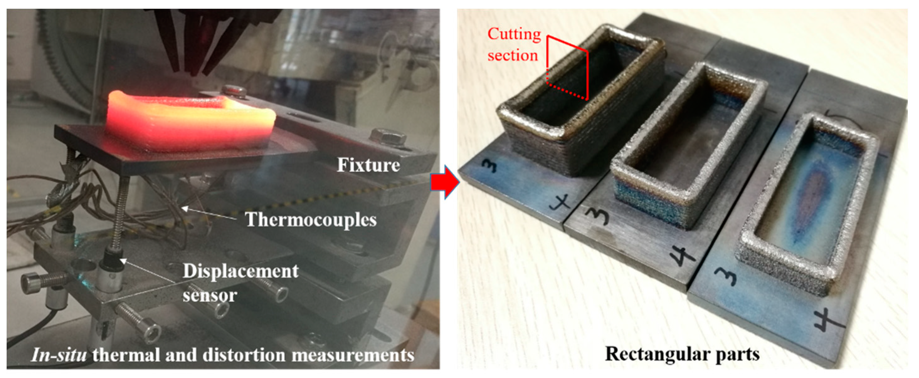
2.1. Experimental Procedure

Three rectangular-shaped workpieces are fabricated on an annealed Ti-6Al-4V baseplate (140 × 50 × 6 mm3) clamped as a cantilever. The spherical filler metal particle is Ti-6Al-4 powder with a size between 53 and 150 μm. Figure 1 shows the adopted L-DED system, which includes a YLS-3000 IPG Photonics fiber laser with a wavelength range from 960 to 1200 nm, a DPSF-2 high-precision adjustable automatic powder feeder, and a robot numerical control system. In-situ measurement equipment is also used to record the temperature and the vertical displacement of the baseplate.
Figure 2 shows the deposition strategy and the workpiece dimensions of the rectangular part, as well as the locations of the thermocouples and displacement sensors. Note that the rectangular structures are built with 4 different sequences looped every 4-layers. The components consist of 44 L-DED layers.
Two WXXY PM11-R1-20L displacement sensors with measurement inaccuracy of 0.02% and a maximum range of 20 mm are employed to record the vertical displacement of points DS1 and DS2 at the bottom surface of the baseplate, as shown in Figure 2. Omega GG-K-30 thermocouples (OMEGA Engineering, Norwalk, CT, USA) with measurement inaccuracy of 7.5% or 2.2 °C are used to capture the temperature histories of the plate bottom. All thermal and displacement signals are collected by a Graphtec GL-900 8-channel high-speed data-logger (Graphtec Corporation, Yokohama, Japan). Table 1 shows three different sets of process parameters adopted to fabricate the rectangular parts.

2.2. Modeling Methodology for L-DED Processes

COMET, a coupled thermo-mechanical FE software developed at CIMNE [20], is used to predict the L-DED processes for the different building strategies. The simulation procedure is achieved by moving the heat source along the user-defined printing strategy. Deposited elements are gradually activated by a born-dead-element technique to identify whether the elements belong to the molten pool area [3]. At each time step, a staggered solution is sequentially implemented for the thermal and mechanical analyses. Hence, a weak coupled thermo-mechanical analysis is done via the user-defined temperature-dependent material database. A detailed description of the employed thermo-viscoelasto-viscoplastic constitutive model suitable for AM used in this paper can be found in references [3,21].
Figure 3 shows the FE model of the rectangular structure of 70 mm length and 30 mm width, which is utilized to calibrate the L-DED model. It consists of 57,880 Q1P0 hexahedral elements and 71,391 nodes. The sizes of the deposited elements are 1 × 1 mm2 in the horizontal plane and one element per layer, based on mesh sensitivity analyses [4,7]. Note that the substrate mesh is proportionally coarsened far from the metal deposition zone, guaranteeing the numerical accuracy of the solution and the computational efficiency.
Both the baseplate and metal powder are considered to be isotropic and to have the same physical and mechanical properties. Table 2 lists the material properties of the Ti-6Al-4V alloy dependent on temperature, adopted in all the analyses [22]. The effect of temperature above the molten point in the molten pool results in an artificially assumed high heat conductivity, as reported in reference [23].
During the thermal analysis for the L-DED process, radiation and convection effects between the part and its surroundings are considered in all the external surfaces of both the baseplate and the depositions. In the L-DED process, a heat convective coefficient of h = 1 W/(m2·°C) is used, and the heat transfer coefficient (HTC) by emissivity is fixed to ε = 0.285 . A higher HTC of h = 50 W/(m2·°C) is applied to simulate the heat transfer condition at the contact interface between the fixture and the baseplate. Room temperature is kept at T e n v = 25   °C, and the laser absorptivity for the L-DED process is set at η = 0.3 . All processing and material parameters applied in the numerical prediction are determined from experimental evidence.

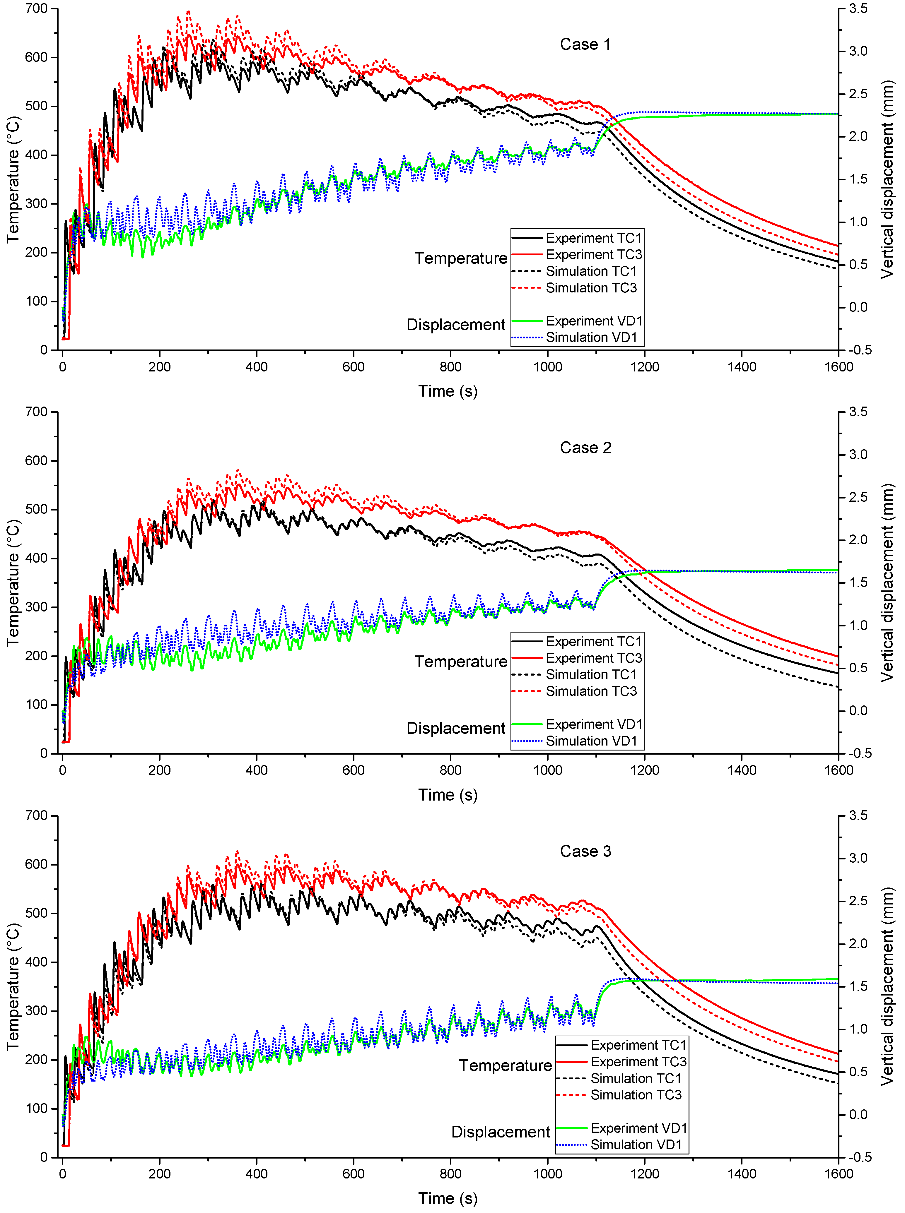
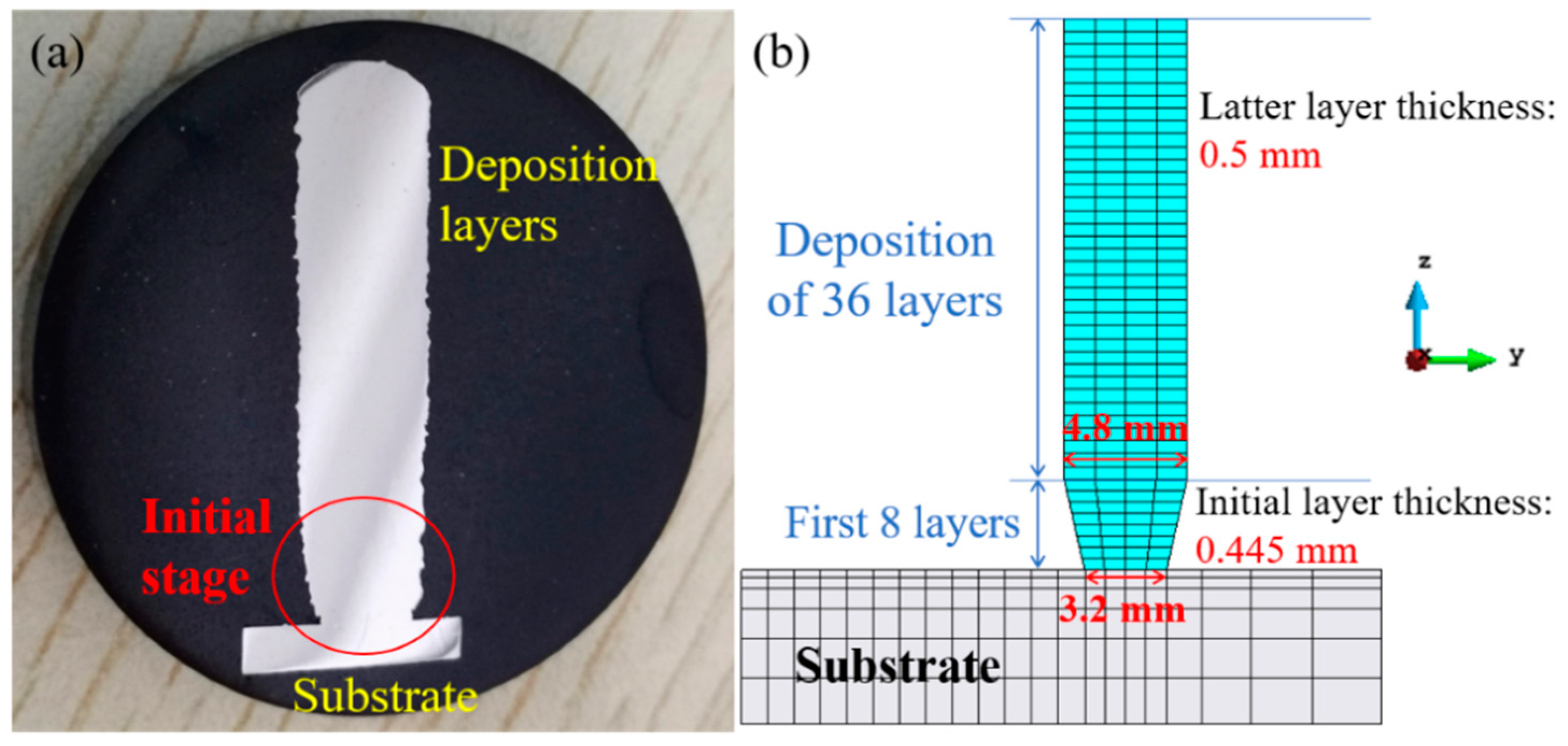
3. Model Calibration

Before the thermo-mechanical software is used to investigate the effect of the alternative building strategies on the response of the parts, the computational model needs to be calibrated and its accuracy assessed. This procedure, regarding the rectangular parts examined in this work, has been performed and reported in reference [5]. Figure 4 summarizes the results obtained in the calibration stage. It is remarkable that numerical predictions agree with experimental measurements for all cases. In addition, it can be observed that increasing the laser power remarkably increases the part temperature and the final vertical displacement of the free end of the baseplate, while varying the power feeding rate hardly affects the thermo-mechanical responses.
There is a slight difference between the experimental and the numerical results. The major reason for this is the simplification of the boundary conditions used in the numerical simulation and the measuring errors during the L-DED process. Notably, in the initial fabrication phase, the geometric dimension of the molten pool is notoriously limited by the cold baseplate, contributing to a small width and thickness of the cladding track, as shown in Figure 5a. As the deposited layers increase, the built layer sizes gradually increase until it stabilizes [24,25]. However, the geometric mesh model uses an average layer-thickness (and width) calculated by the final built height divided as fact the total number of layers [26,27,28]. This is responsible for the initial mismatch in the displacement prediction. In order to improve the resulting accuracy of the mechanical model, a modified geometry mesh model referring to the actual deposition sizes is used, as shown in Figure 5b. Figure 6 compares the predicted displacement histories between the improved model and the experimental reference. A remarkable improvement in the warpage prediction is achieved by the upgraded model. The developed numerical technique can be implemented in other applications of AM research. In this work, the slight variation of the layer dimensions in the initial deposition process for different building strategies is not implemented as the qualitative comparison of the thermal and mechanical responses due to the building strategy is investigated. Therefore, all the numerical investigations for different building strategies use uniform layer thickness.

4. Effect of the Building Strategy

To study the residual stresses and warpage of rectangular Ti-6Al-4V parts, six types of scanning patterns are designed, as shown in Figure 7. Path A uses a cycling printing strategy for the entire buildup. In paths B and C, each layer is split into two parts to be cladded, but the laser start point is different for both. Path D adopts alternative start points in the middle of the long-walls to deposit each layer. In the case of path E, the short-walls and long-walls are scanned counterclockwise and clockwise, respectively. Finally, path E uses several short scan vectors and changes the deposition sequence between the odd and even layers.
It is to be mentioned that the back speed has an influence on the dwell-time as discontinuous scanning lines within the same layer or between adjacent layers occur. Hence, the effect of different back speeds on thermo-mechanical responses of rectangular parts first is investigated to decrease the interference of the dwell-time. Next, a higher back speed of 50 mm/s is used in all numerical samples to study six different scanning paths (Figure 7). For each case, the settings of the substrate and deposition sizes, the boundary conditions, and the process parameters (Table 1) in simulations are in line with the numerical model of the actual rectangular workpieces.

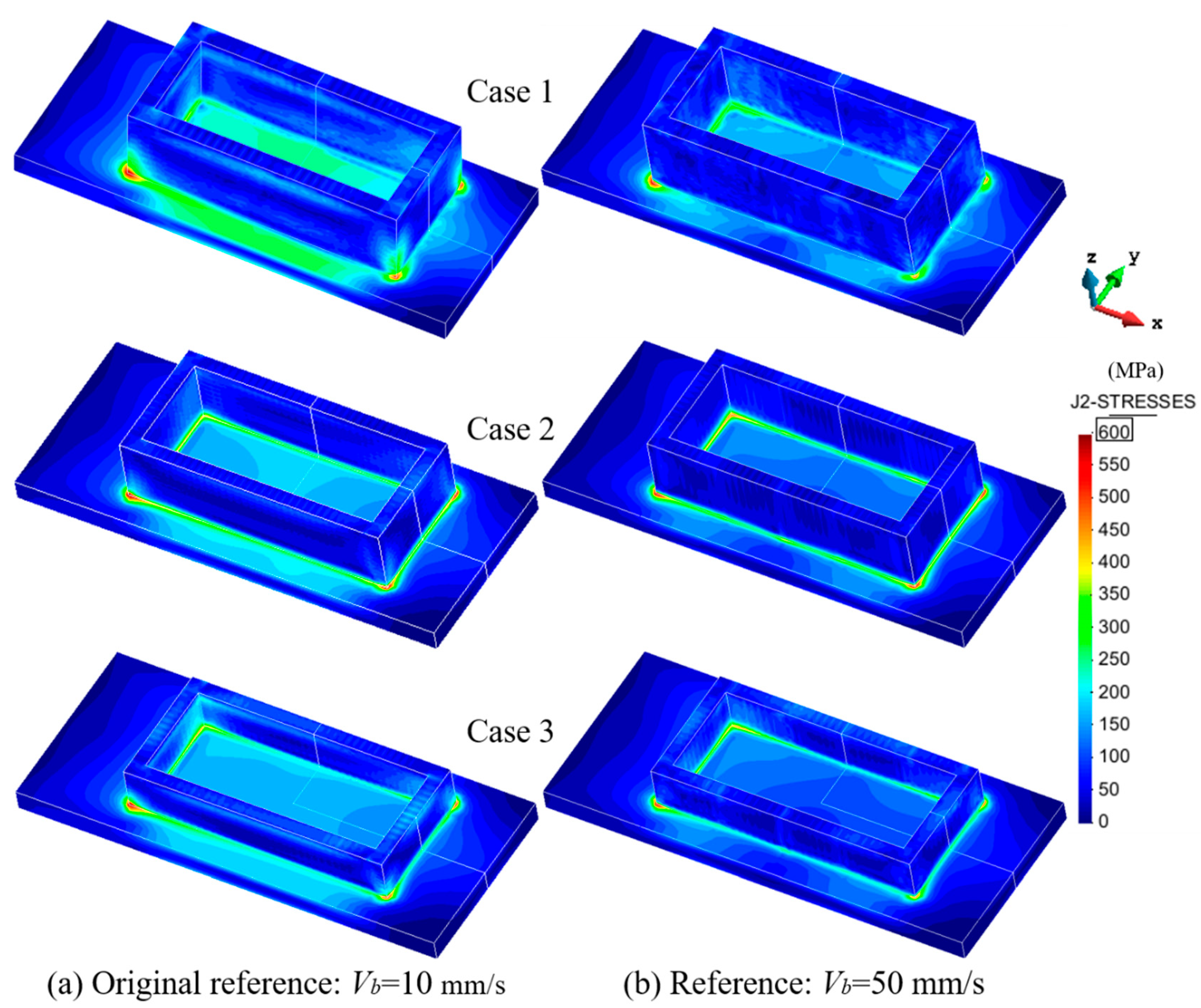
4.1. Effect of the Back Speed

4.1.1. Thermal Response

Based on the validated FE model, the thermal responses of the rectangular specimens using different back speeds are predicted. Figure 8 compares the temperature histories of point P at the middle/top of the baseplate (see Figure 3) for the three cases in Table 1 and two different back speeds. Point P is selected to represent the temperature field evolution of the baseplate. Note that increasing the back speed enlarges the heat accumulation in the part while reducing the buildup time by about 200 s. Compared with the original reference representing the actual part, both the peak and final values of temperature after completing the last layer increase by approximately 30 °C using a higher back speed of 50 mm/s. The reason for this is that the higher the back speed, the shorter the dwell-time (cooling time) becomes during the building process. As a result, the increasing heat accumulation favors stress relaxation in the built [1,9].

4.1.2. Mechanical Response

Figure 9 compares the evolution of the vertical displacement of point DS1 (Figure 2) when varying the back speed. It can be seen that using a higher back speed achieves a notable warpage reduction due to stress relief. For the three cases studied, the decreased amount of the final vertical displacement is 0.5 mm, 0.26 mm, and 0.29 mm, respectively. Obviously, Case 1, with higher laser power, achieves the larger stress relief and warpage mitigation.
Figure 10 compares the residual von Mises stress field distributions for two different back speeds. It can be seen that the biggest stresses are located at the interfaces between the deposition and baseplate for all samples. Although increasing the back speed fails to reduce the largest stress at the corners of the rectangular parts, it mitigates the compressive stress level on the substrate top. This demonstrates that smaller tensile stresses are generated in the rectangular sample during the building process.

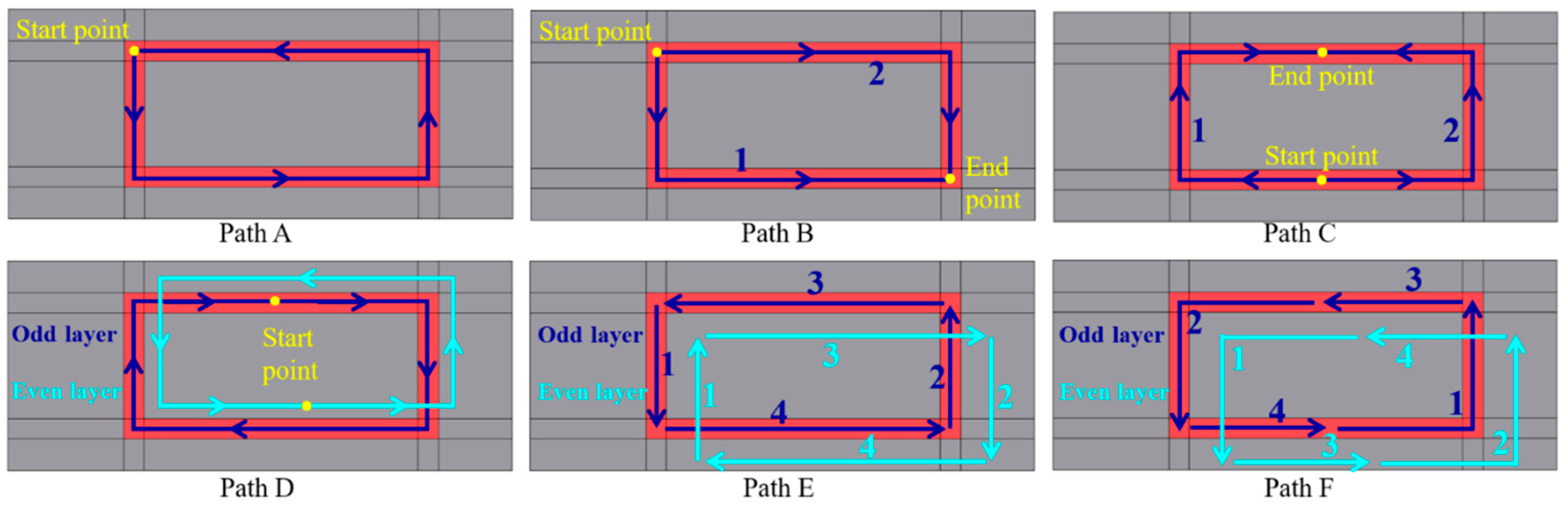
4.2. Effect of the Scanning Pattern

To reduce the dwell-time effect, the high back speed of 50 mm/s is now used in all numerical samples to analyze the influence of the scanning pattern on the thermo-mechanical response in the L-DED process.

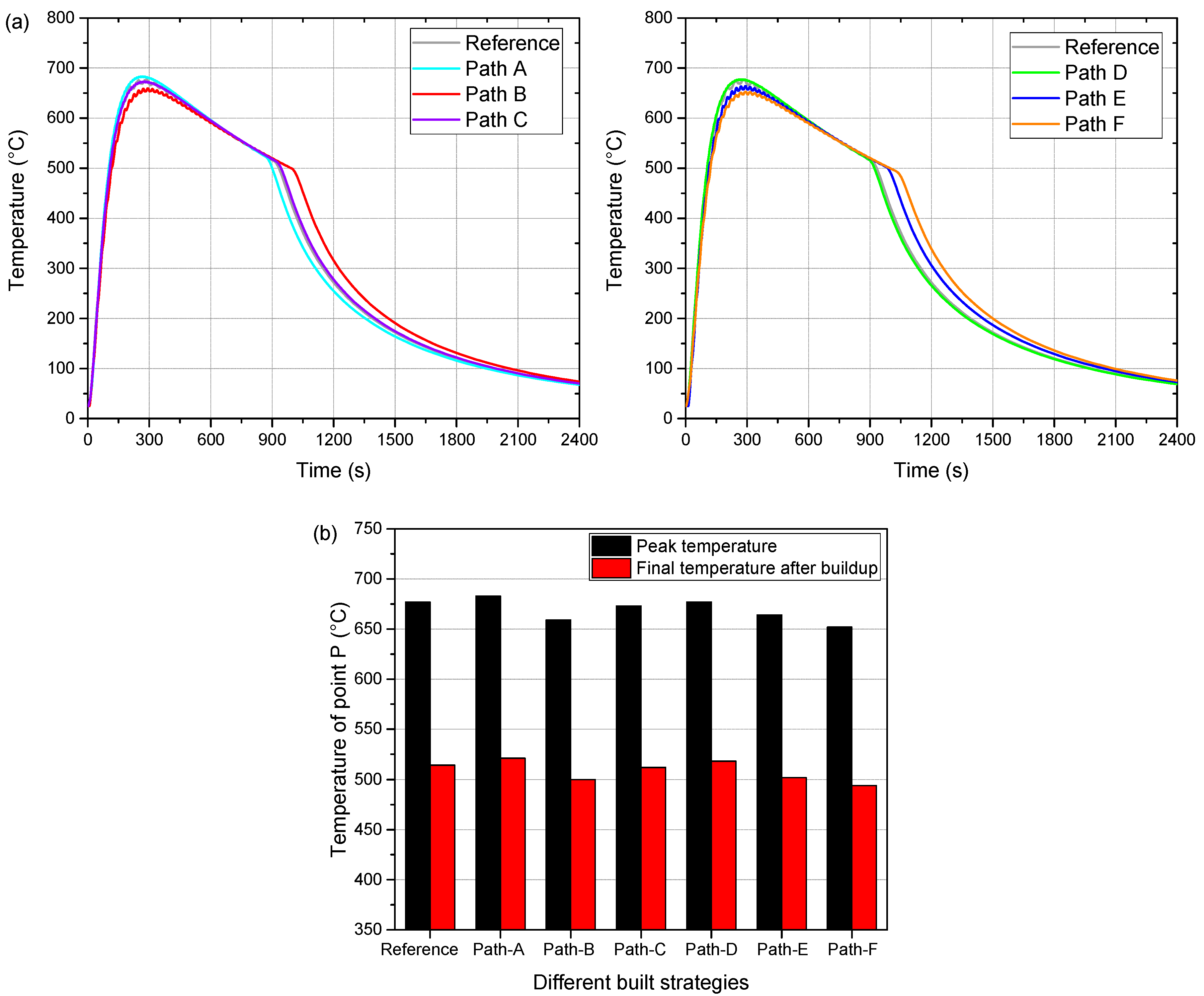
4.2.1. Temperature Evolution

On the basis of the validated FE model, the temperature evolution for six different scanning strategies are predicted. Figure 11 shows the thermal histories of point P (see Figure 3) under Case 1 during the building process. It can be seen from Figure 11a that varying the scanning strategy hardly changes the temperature profile. The shorter the building process, the higher the peak temperature. It can be seen in Figure 11b that compared with the reference, only the specimen using path A attains a slightly increased temperature, while the other cases produce lower or unchanged temperature levels.

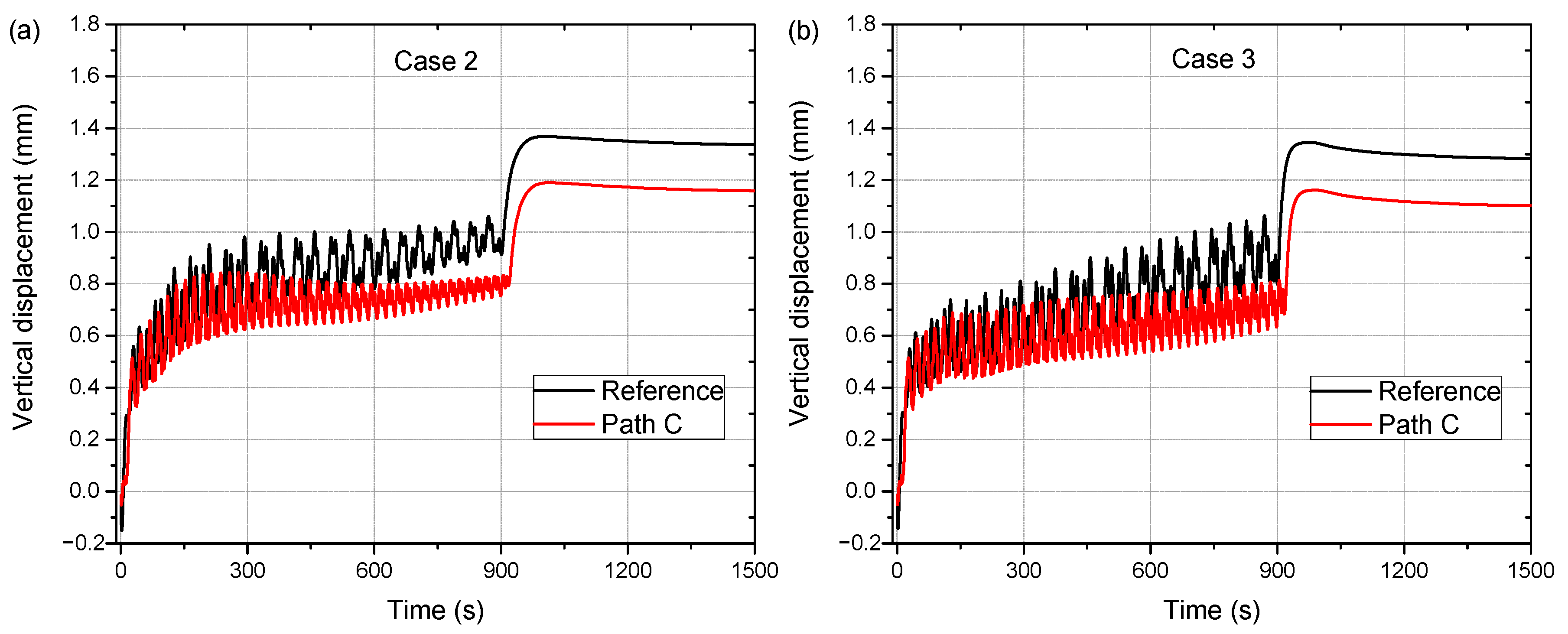
4.2.2. Displacement History

Figure 12a shows the vertical displacement histories of point DS1 (Figure 2) for Case 1 for different scanning strategies. Figure 12b compares the final displacements of the baseplate. Note that, compared with the reference, using paths A and C achieves a noteworthy warpage reduction, but larger residual displacements are produced for paths E and F. The displacement for path B is almost the same as for the reference, and only slight deformation mitigation is obtained by adopting path D. These results can be explained by the following.
In path A, there is no dwell-time during the building process, contributing to heat accumulation in part and consequent stress relief. In path C, the length of the longitudinal scanning vectors is cut down, which decreases the tensile stress along the long-wall direction [29]. Therefore, small part warpage is generated in these two cases. Compared with path C, path D entails a larger displacement because it has a long scanning vector for each deposited layer. Furthermore, the longitudinal long scanning vectors in paths B and E are responsible for the deformation of the baseplate. Finally, although path F eliminates the long scanning vector, the discontinuous depositions lead to an increasing dwell-time during the building process and, consequently, the triggering of a pronounced warpage accumulation.
Figure 13 compares the displacement histories of point DS1 between the reference path and path C under Cases 2 and 3. Employing path B strategy achieves a notable deformation reduction for both cases. Table 3 summarizes the warpage reduction of point DS1 for different building strategies in terms of the scanning path and process parameters. When path B is used, the final displacements under the three cases are mitigated by 36.4%, 25.8%, and 32.5%, respectively.

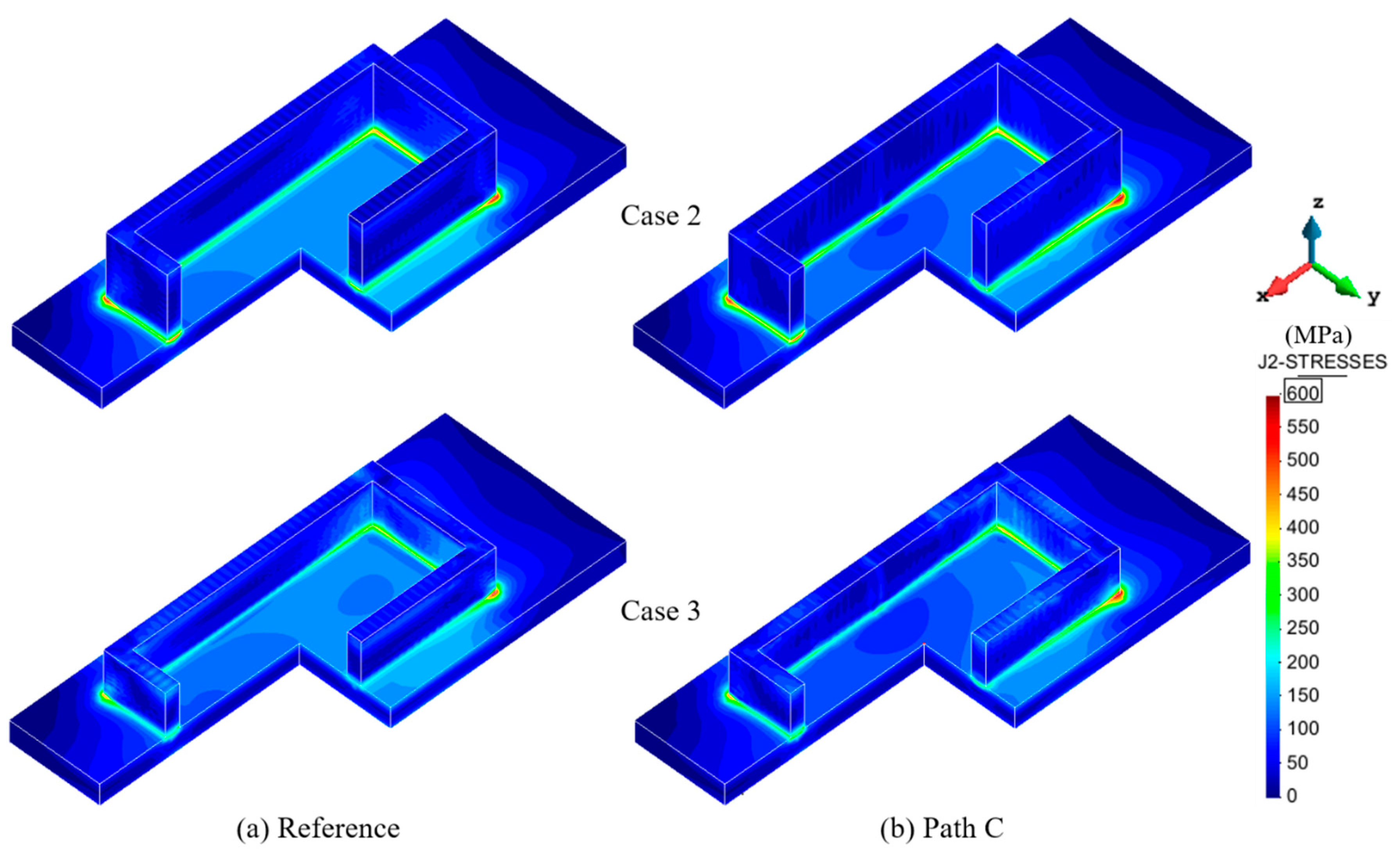
4.2.3. Residual Stresses

In order to understand why a shorter scanning vector can generate smaller part warpage (see Figure 12 and Figure 13), the evolution of the longitudinal stress field between the original reference (Figure 2) and path C under Case 1 is compared and shown in Figure 14. Correspondingly, Figure 15 gives the comparison of the variation of the temperature and longitudinal stress of point Q at the bottom/middle of the deposited long-wall (see Figure 3).
It can be observed from Figure 14 that after the building of the first layer, both cases produce higher stress along the long-wall due to the rapid cooling and shrinkage of the cladding layer. Notably, the distributions of the longitudinal stresses are, respectively, continuous and discontinuous for the original reference and path C when the first layer is deposited. Such a situation is maintained for upper deposited layers even if the stress level decreases dramatically on account of the increasing substrate temperature. After the buildup, the reference sample generates larger compressive stresses on the substrate top than the case under path C, owing to the continuous longitudinal stress along the long-wall. In addition, it can be seen in Figure 15 that the higher the temperature becomes, the lower the corresponding stress is, and vice versa. Compared with the original reference, the sample under path C experiences lower longitudinal stress during the fabricating process, contributing to the small displacement along the building direction (see Figure 12).
Figure 16 compares the residual von Mises stress fields for Case 1 for different scanning paths. It can be found that the highest residual stress zone still occurs on the interface between the deposition and substrate for all cases. Compared with the reference, path C produces a slightly smaller residual stress on the top surface of the substrate. However, there are no obvious differences in the stress profiles for different cases. Figure 17 shows the comparison of the residual von Mises stress field between the reference path and path C under Cases 2 and 3. Again, the difference in the residual stress fields is small. Hence, varying the scanning strategy fails to mitigate the residual stresses of the rectangular workpieces.

5. Conclusions

In this paper, an experimentally calibrated 3D FE model for AM is used to study the effect of different building strategies on the warpage and stress development of Ti-6Al-4V rectangular workpieces manufactured by the L-DED technology. Distinctive conclusions are:
  • Remarkable agreement between the predicted and experimental thermal and mechanical results provides confidence for adopting the high-fidelity model to explore diverse thermo-mechanical problems in the AM. Considering the actual layer sizes in numerical modeling improves the accuracy of the mechanical predictions.
  • Controlling the back speed is beneficial to reduce the dwell-time during the manufacturing process. The shorter the dwell-time is, the higher the heat accumulation becomes, which triggers heat softening and stress relief, leading to the mitigation of both residual stress and distortion.
  • Shortening the longitudinal scanning vectors significantly alleviates the effect of the longitudinal tensile stress along the long-wall direction, contributing to the reduction of the part warpage.
  • Using an optimized scanning strategy can achieve a pronounced minimization in vertical displacement (36.4%) but fails to control the development of the thermal stresses in the manufacturing process.
  • In order to control both residual stress and deformation of the rectangular workpieces, the combination of shortening the scanning vector and preheating the baseplate before L-DED is needed [5].

Author Contributions

Conceptualization, X.L. (Xufei Lu) and M.C. (Michele Chiumenti); methodology and software, M.C. (Michele Chiumenti) and M.C. (Miguel Cervera); data curation, X.J. and X.L. (Xufei Lu); writing—original draft preparation, X.L. (Xufei Lu) and J.L.; writing—review and editing, G.Z., M.C. (Miguel Cervera), and X.L. (Xin Lin); supervision, J.L. and X.L. (Xin Lin). All authors have read and agreed to the published version of the manuscript.

Funding

This research was funded by the National Key Technologies R & D Program (No. 2016YFB1100104) and the China Scholarship Council (No. 201906290011). Funding from the Spanish Ministry of Economy and Competitivity (MINECO) under the ADaMANT project: Computational Framework for Additive Manufacturing of Titanium Alloy Components (ref: DPI2017-85998-P), within the Excellency Programme for Knowledge Generation, is gratefully acknowledged. CIMNE is the recipient of the Severo Ochoa Award of Excellence from MINECO. This work was also funded by the European KYKLOS 4.0 project: An Advanced Circular and Agile Manufacturing Ecosystem based on rapid reconfigurable manufacturing process and individualized consumer preferences (No. H2020-DT-2019-1).

Conflicts of Interest

The authors declare no conflict of interest.

References

  1. Lu, X.; Lin, X.; Chiumenti, M.; Cervera, M.; Li, J.; Ma, L.; Wei, L.; Hu, Y.; Huang, W. Finite element analysis and experimental validation of the thermomechanical behavior in Laser Laser Directed energy deposition of Ti-6Al-4V. Addit. Manuf. 2018, 21, 30–40. [Google Scholar]
  2. Guo, P.; Lin, X.; Liu, J.; Xu, J.; Li, J.; Zhang, Y.; Lu, X.; Qu, N.; Lan, H.; Huang, W. Passive behavior of nickel-based superalloys prepared by high-deposition-rate laser solid forming additive manufacturing. Corros. Sci. 2020, 177, 109036. [Google Scholar] [CrossRef]
  3. Chiumenti, M.; Cervera, M.; Salmi, A.; De Saracibar, C.A.; Dialami, N.; Matsui, K. Finite element modeling of multi-pass welding and shaped metal deposition processes. Comput. Methods Appl. Mech. Eng. 2010, 199, 2343–2359. [Google Scholar] [CrossRef]
  4. Cao, J.; Gharghouri, M.A.; Nash, P. Finite-element analysis and experimental validation of thermal residual stress and distortion in electron beam additive manufactured Ti-6Al-4V build plates. J. Mater. Process. Technol. 2016, 237, 409–419. [Google Scholar] [CrossRef]
  5. Lu, X.; Lin, X.; Chiumenti, M.; Cervera, M.; Hu, Y.; Ji, X.; Ma, L.; Yang, H.; Huang, W. Residual stress and distortion of rectangular and S-shaped Ti-6Al-4V parts by Directed Energy Deposition: Modelling and experimental calibration. Addit. Manuf. 2019, 26, 166–179. [Google Scholar] [CrossRef]
  6. Michael, G.; Michaleris, P. (Eds.) Thermo-Mechanical Modeling of Additive Manufacturing; Butterworth-Heinemann: Oxford, UK, 2017. [Google Scholar]
  7. Chiumenti, M.; Lin, X.; Cervera, M.; Lei, W.; Zheng, Y.; Huang, W. Numerical simulation and experimental calibration of additive manufacturing by blown powder technology. Part I: Thermal analysis. Rapid Prototyp. J. 2017, 23, 448–463. [Google Scholar] [CrossRef] [Green Version]
  8. Lindgren, L.-E.; Lundbäck, A.; Malmelöv, A. Thermal stresses and computational welding mechanics. J. Therm. Stress. 2019, 42, 107–121. [Google Scholar] [CrossRef] [Green Version]
  9. Denlinger, E.R.; Michaleris, P. Effect of stress relaxation on distortion in additive manufacturing process modeling. Addit. Manuf. 2016, 12, 51–59. [Google Scholar] [CrossRef] [Green Version]
  10. Chen, Z.; Ye, H.; Xu, H. Distortion control in a wire-fed electron-beam thin-walled Ti-6Al-4V freeform. J. Mater. Process. Technol. 2018, 258, 286–295. [Google Scholar] [CrossRef]
  11. Wang, Z.; Stoica, A.D.; Ma, D.; Beese, A.M. Stress relaxation behavior and mechanisms in Ti-6Al-4V determined via in situ neutron diffraction: Application to additive manufacturing. Mater. Sci. Eng. A 2017, 707, 585–592. [Google Scholar] [CrossRef]
  12. Setien, I.; Chiumenti, M.; Van Der Veen, S.; Sebastian, M.S.; Garciandía, F.; Echeverría, A. Empirical methodology to determine inherent strains in additive manufacturing. Comput. Math. Appl. 2019, 78, 2282–2295. [Google Scholar] [CrossRef] [Green Version]
  13. Lu, X.; Lin, X.; Chiumenti, M.; Cervera, M.; Hu, Y.; Ji, X.; Ma, L.; Huang, W. In situ Measurements and Thermo-mechanical Simulation of Ti-6Al-4V Laser Laser Directed energy deposition Processes. Int. J. Mech. Sci. 2019, 153, 119–130. [Google Scholar] [CrossRef]
  14. Levkulich, N.; Semiatin, S.; Gockel, J.; Middendorf, J.; Dewald, A.; Klingbeil, N. The effect of process parameters on residual stress evolution and distortion in the laser powder bed fusion of Ti-6Al-4V. Addit. Manuf. 2019, 28, 475–484. [Google Scholar] [CrossRef]
  15. Li, H.; Ramezani, M.; Chen, Z.; Singamneni, S. Effects of Process Parameters on Temperature and Stress Distributions During Selective Laser Melting of Ti-6Al-4V. Trans. Indian Inst. Met. 2019, 72, 3201–3214. [Google Scholar] [CrossRef]
  16. Wu, Q.; Mukherjee, T.; Liu, C.; Lu, J.; Debroy, T. Residual stresses and distortion in the patterned printing of titanium and nickel alloys. Addit. Manuf. 2019, 29, 100808. [Google Scholar] [CrossRef]
  17. Ramos, D.; Belblidia, F.; Sienz, J. New scanning strategy to reduce warpage in additive manufacturing. Addit. Manuf. 2019, 28, 554–564. [Google Scholar] [CrossRef]
  18. Cheng, B.; Shrestha, S.; Chou, K. Stress and deformation evaluations of scanning strategy effect in selective laser melting. Addit. Manuf. 2016, 12, 240–251. [Google Scholar] [CrossRef]
  19. Robinson, J.; Ashton, I.; Fox, P.; Jones, E.; Sutcliffe, C. Determination of the effect of scan strategy on residual stress in laser powder bed fusion additive manufacturing. Addit. Manuf. 2018, 23, 13–24. [Google Scholar] [CrossRef]
  20. Cervera, M.; de Saracibar, C.A.; Chiumenti, M. COMET: Coupled Mechanical and Thermal Analysis. Data Input Manual, Version 5.0, Technical Report IT-308. 2002. [Google Scholar]
  21. Chiumenti, M.; Cervera, M.; Dialami, N.; Wu, B.; Jinwei, L.; De Saracibar, C.A. Numerical modeling of the electron beam welding and its experimental validation. Finite Elem. Anal. Des. 2016, 121, 118–133. [Google Scholar] [CrossRef] [Green Version]
  22. Parry, L.; Ashcroft, I.A.; Wildman, R.D. Understanding the effect of laser scan strategy on residual stress in selective laser melting through thermo-mechanical simulation. Addit. Manuf. 2016, 12, 1–15. [Google Scholar] [CrossRef] [Green Version]
  23. Fallah, V.; Alimardani, M.; Corbin, S.F.; Khajepour, A. Temporal development of melt-pool morphology and clad geometry in laser powder deposition. Comput. Mater. Sci. 2011, 50, 2124–2134. [Google Scholar] [CrossRef]
  24. Wang, J.; Lin, X.; Li, J.; Hu, Y.; Zhou, Y.; Wang, C.; Li, Q.; Huang, W. Effects of deposition strategies on macro/microstructure and mechanical properties of wire and arc additive manufactured Ti 6Al 4V. Mater. Sci. Eng. A 2019, 754, 735–749. [Google Scholar] [CrossRef]
  25. Baykasoğlu, C.; Akyildiz, O.; Tunay, M.; To, A.C. A process-microstructure finite element simulation framework for predicting phase transformations and microhardness for directed energy deposition of Ti6Al4V. Addit. Manuf. 2020, 35, 101252. [Google Scholar] [CrossRef]
  26. Hönnige, J.; Colegrove, P.; Ahmad, B.; Fitzpatrick, M.; Ganguly, S.; Lee, T.; Williams, S. Residual stress and texture control in Ti-6Al-4V wire + arc additively manufactured intersections by stress relief and rolling. Mater. Des. 2018, 150, 193–205. [Google Scholar] [CrossRef] [Green Version]
  27. Xiong, J.; Li, R.; Lei, Y.; Chen, H. Heat propagation of circular thin-walled parts fabricated in additive manufacturing using gas metal arc welding. J. Mater. Process. Technol. 2018, 251, 12–19. [Google Scholar] [CrossRef]
  28. Denlinger, E.R.; Heigel, J.C.; Michaleris, P. Residual stress and distortion modeling of electron beam direct manufacturing Ti-6Al-4V. Proc. Inst. Mech. Eng. Part B J. Eng. Manuf. 2015, 229, 1803–1813. [Google Scholar] [CrossRef]
  29. Promoppatum, P.; Yao, S.-C. Influence of scanning length and energy input on residual stress reduction in metal additive manufacturing: Numerical and experimental studies. J. Manuf. Process. 2020, 49, 247–259. [Google Scholar] [CrossRef]
Figure 1. In-situ measurement setup during the laser directed energy deposition (L-DED) process.
Metals 10 01643 g001
Figure 2. Rectangular part: (a) part dimensions (mm) and locations of the thermocouples and displacement sensors; (b) building path.
Metals 10 01643 g002
Figure 3. The finite element (FE) mesh model of the rectangular part used to calibrate the FE model.
Metals 10 01643 g003
Figure 4. Comparison between calculated and experimental thermo-mechanical results of the rectangular parts under three different process parameters.
Metals 10 01643 g004
Figure 5. (a) Varying layer sizes in the initial building stage (see Figure 1); (b) modified geometric mesh model referring to the actual workpiece.
Metals 10 01643 g005
Figure 6. Rectangle under Case 1: comparison of the distortion histories of the substrate between the reference simulation and the upgraded model.
Metals 10 01643 g006
Figure 7. Schematic of six different building strategies for rectangular parts in L-DED.
Metals 10 01643 g007
Figure 8. Temperature histories of point P (see Figure 3): (a) Case 1; (b) Case 2; (c) Case 3; (d) comparison of peak and final temperatures after the last layer for the three cases.
Metals 10 01643 g008
Figure 9. Evolutions of the vertical displacement of point DS1 (see Figure 2): (a) Case 1; (b) Case 2; (c) Case 3; (d) final displacement under three cases.
Metals 10 01643 g009
Figure 10. Residual von Mises stress fields for the three cases in Table 1 and two different back speeds.
Metals 10 01643 g010
Figure 11. Predicted thermal responses of point P (see Figure 3) for Case 1: (a) thermal histories; (b) peak and final temperatures after the last layer under different scanning strategies.
Metals 10 01643 g011
Figure 12. Predicted substrate warpage for Case 1 for different scanning strategies: (a) vertical displacement history of point DS1; (b) final vertical displacements of point DS1.
Metals 10 01643 g012
Figure 13. Comparison of the displacement evolutions of point DS1 between the reference and path C: (a) Case 1; (b) Case 2.
Metals 10 01643 g013
Figure 14. Rectangular part: the evolution of the longitudinal stress (σxx) field under Case 1 for different building times.
Metals 10 01643 g014
Figure 15. Comparison between the temperature and longitudinal stress (σxx) of point Q (see Figure 3): (a) original reference; (b) path C.
Metals 10 01643 g015
Figure 16. Comparison of residual von Mises stress field under Case 1 for different building strategies.
Metals 10 01643 g016
Figure 17. Comparison of residual von Mises stress field between the reference path and path C under Cases 2 and 3.
Metals 10 01643 g017
Table 1. Processing parameters of laser directed energy deposition (L-DED).
Case123
Laser power P (W)150010001000
Beam radius d (mm)444
Scanning speed V (mm/s)101010
Back speed Vb (mm/s)101010
Up-lift height ΔZ (mm)0.450.400.25
Feeding rate f (g/min)12.012.08.0
Table 2. Temperature-dependent material properties of Ti-6Al-4V alloy, data from [22,23].
Temperature (°C)2020550099511001200160016502000
Density (kg/m3)442043954350428242674252419838863818
Thermal conductivity
(W/(m·°C))
78.7512.622.719.32125.883.583.5
Heat capacity (J/(kg·°C))546584651753641660732831831
Poisson’s ratio0.3450.350.370.430.430.430.430.430.43
Thermal expansion coefficient
(μm/m/°C)
8.781011.212.312.412.4212.512.512.5
Young’s modulus (GPa)11010076155410.10.01
Elastic limit (MPa)85063047013510.50.10.01
Table 3. Warpage reduction (%) of point DS1 for different building strategies compared to the original reference (100%).
Case 1Case 2Case 3
Ref.Path APath BPath CPath DPath EPath FRef.Path CRef.Path C
Warpage reduction21.934.222.436.428.918.416.716.825.817.832.5
Publisher’s Note: MDPI stays neutral with regard to jurisdictional claims in published maps and institutional affiliations.

