Article

General Research on the Process of the Indirect Hot Stamping Ultra-High-Strength Steel

1
Department of Materials Science and Engineering, Key Laboratory of Automobile Materials, Jilin University, Changchun 130022, China
2
Roll Forging Research Institute, Jilin University, Changchun 130022, China
*
Author to whom correspondence should be addressed.
Metals 2020, 10(12), 1658; https://doi.org/10.3390/met10121658
Submission received: 13 November 2020 / Revised: 2 December 2020 / Accepted: 4 December 2020 / Published: 10 December 2020
(This article belongs to the Section Metal Casting, Forming and Heat Treatment)

Abstract

:
Aiming at the need for lightweight requirements of the components in the bus, combined with the advantages of the hot stamping ultra-high-strength steel, a new television (TV) bracket was proposed. The finite element (FE) simulation of the beam part in the TV bracket during the indirect hot stamping process was discussed. After two-stages of pre-forming, the blank was in good formability and without visible cracks. According to the FE simulation results, the punch speed, quenching force, and quenching time significantly affected the temperature, microstructure, hardness, and mechanical properties of the beam part during hot stamping. With the increase of the quenching force and quenching time, the martensite fraction of the beam part was increased. For the beam part, the punch speed should be at least 80 mm/s during the forming stage. For complete quenching, the quenching force should be above 1000 kN and quenching time should be up to 10 s. Based on the parameters from the FE simulation, the forming experiment of the beam part was discussed. Microstructure analyses and microhardness tests as well as tensile tests of the hot stamping beam part were performed. The results confirmed that the FE simulation of the beam part was reliable.

1. Introduction

Lightweight has become an inevitable trend under energy and sustainable development in the bus. Lightweight requires making the components lighter and, at the same time, stronger. Then choosing the applicable lightweight materials is a relatively mature lightweight technology to effectively facilitate energy conservation and emission reduction [1]. Also, the optimized design is always required in the bus and, compared with reducing the weight of the bus body, the lightweight design of the interior components in the carriages will be easy to achieve and greatly reduce the time and costs [2,3]. High-strength steel, aluminum alloys, magnesium alloys, and composites have been used for the components in the bus [4,5,6]. Nowadays, ultra-high-strength steel (UHSS) has occupied a certain place in the automotive industry. Combined with the hot stamping process, this kind of material allows manufacturing parts with ultra-high strength, minimum springback, and reduced sheet thickness [7,8]. Because the stress level and the hardening of the UHSS decrease at higher temperatures, hot stamping allows UHSS forming of complex parts for which the production with conventional methods is either impossible or extremely difficult. Since hot stamping allows forming the complex parts, multi-component assemblies can be redesigned and formed as one component, eliminating some downstream joining processes such as welding or joining. It can be divided into direct hot stamping and indirect hot stamping. Normally, indirect hot stamping was developed to reduce wear on the tools when dealing with uncoated steel and to form more complex shape features [9]. Although UHSS is not commonly used on the bus, with the application of hot stamping this kind of material will become a way for the lightweight design of the bus in the future.
As hot stamping is a relatively new process, extensive practical experience is not available. Thus, it makes sense to apply the numerical simulation for this forming method. Finite element (FE) simulation is becoming an increasingly important tool in the process design for structural components that are manufactured using the hot stamping method [10,11]. A hot stamping process is a combination of the mechanical field, microstructure, and thermal field [12,13]. Thus, suitable forming processes have to be identified early during part design or tool design to avoid time-consuming and expensive tryouts [14]. Besides several studies on the direct hot stamping for the parts with simple geometries, there are few types of research focused on manufacturing complex shape components and the influences of parameters during the indirect hot stamping process [15].
In this paper, a new television (TV) bracket was redesigned and combined with the advantage of UHSS to reduce the weight of the bus. The FE simulation was used to propose a detailed process plan of the TV bracket component manufactured by the indirect hot stamping process. At the same time, the influences of process parameters such as the punch speed, quenching force, and quenching time on the distribution of the temperature, microstructure, and hardness of the beam part were investigated. Finally, experiments were carried out to manufacture the beam part and validate the correctness of the FE simulation results.

2. Model of the New TV Bracket

2.1. Design of the New TV Bracket

There are many TVs that are installed in the carriage of the bus. A TV bracket is a structure for hoisting two TVs and it is installed on the roof of the carriage. After structural optimization, the new TV bracket consists of the arms, middle connections, joints, and beam. Each component was connected with bolts. The new TV bracket was designed through 3D modeling using the computer aided design (CAD) system CATIA V5, and the detailed characteristics of the beam part are shown in Figure 1. Each component used 22MnB5 steel with a thickness of 2 mm. Among the components of the TV bracket, the beam part was the most important and played the role of ceiling TVs. The beam part is mainly composed of four, deep, concave-convex structures in the middle section and four, shallow, concave-convex structures at both ends of the part. The transition area between the deep and the shallow concave-convex is automatic-lofting generated. Due to the complicated profile of the part, the blank was seriously cracked after direct hot stamping. Thus, to avoid failure, this study manufactured the part by the indirect hot stamping process.

2.2. Finite Element Model

AutoForm R7 software (AutoForm Engineering GmbH, Zurich, Switzerland) was used to carry out the thermal-mechanical coupled simulation of the indirect hot stamping process. The stitching distance and meshing tolerance between the geometric surfaces were set to 0.5 mm and 0.03 mm. During the simulation, an adaptive refinement of the mesh took place. Fnally, there were 380,314 elements and 175,961 nodes. The thermal parameters of 22MnB5 steel were referenced from the information database of AutoForm R7. The detailed material information and simulation conditions are listed in Table 1 and Table 2. The heat transfer coefficient (HTC) depends on the gap and/or the quenching force between sheet and tool, as shown in Figure 2a. Define the pressure dependency of the HTC by a multilinear curve. Pressure equals quenching force divided by the area of the blank. This curve is defined by a number of pressure points. For each pressure, an actual value of the HTC is defined by a percentage value of the HTC. The HTC is extrapolated as a constant value for values greater than the maximum pressure. If there is no contact pressure, the HTC depends on the actual gap size between the tool and the blank. The simulation included a series of hardening curves covering the entire thermoforming temperature, as shown in Figure 2b. Also, the influence of phase transformation and transformation plasticity were considered in the model. The simulation of the beam part manufactured by the indirect hot stamping process was divided into four stages: pre-forming, heating, forming, and quenching. In the first operation, the blank was conventionally preformed about 90% to 95% of the final shape at room temperature. Then the preformed blank was put into a furnace sufficiently heated to 930 °C and held at this temperature for 5 min to guarantee a complete austenitization. The parameters were carried out following the experiments in [16]. After heating, the heated blank was removed from the furnace and transferred to the lower die to form the final shape of the product and then quenching. When the heated blank was transferred from the furnace into the lower die, the temperature of the blank would drop because of the heat convection and heat radiation in the air environment. Thus, to guarantee the initial deformation temperature with the high formability in this simulation the transfer time was within 4 s [17].
In the simulation process, a continuous cooling transformation (CCT) diagram of 22MnB5 was used to predict phase transformation and hardness in the quenching process. For each temperature history path, the resulting final hardness value is given as a measured result. From the CCT diagram, it is indicated that to obtain completely martensite the cooling rate must be at least 27 °C/s. Martensite start temperature (Ms) was around 400 °C and martensite finish temperature (Mf) was around 280 °C [18]. During quenching, austenite transforms to ferrite and pearlite if cooled slowly, bainite forms at a moderate cooling rate, and under a high cooling rate martensite forms. In the FE model, the Avrami Equation (1) is used to model phase transformations. Coefficients of the Avrami equation are b and n where b is a constant set to 0.69, although this is not a mathematical prerequisite, and n is an Avrami exponent [19]. For each phase, these can be calculated by using time temperature transformation (TTT) diagrams at a given temperature.
X p , X b , X f = 1 e x p ( b ( t t 0 ) n )
where X is the phase fraction and subscripts f, p, b, and M stand for ferrite, pearlite, bainite, and martensite. For martensite transformation, the equation slightly changes to Equation (2) [20].
X M = 1 e x p [ α   ( M s T ) ]
where XM stands for martensite fraction, Ms is martensite start temperature, and α is a material-dependent constant that can be set to 0.011.
Based on the Avrami equation, the phase fraction can be estimated. Using phase fraction, hardness can be estimated by Equation (3) [21].
H V = 188.5 ( X f + X p ) + 283.8 X b + 514.4 X M
The FE model during indirect hot stamping is shown in Figure 3. Figure 3a,b was the tool of the pre-forming process. The initial blank has a dimension of 1700 mm × 290 mm × 2 mm and the draw depth of the concave-convex structure is 23 mm. The first stage was to form the two concave-convex structures in the middle of the beam part. The second stage was to form both sides of the concave-convex structures of the beam part. According to the prior analysis results, after two- stages of pre-forming, the blank was in good formability and without visible cracks. In the hot stamping process, the upper die was moved down with the punch speed and the lower die was fixed in all directions, as shown in Figure 3c. During the quenching stage, the dies were clamped with given force. Most heat transfer and phase transformations took place in this stage.

3. Finite Element Analyses

3.1. Effect of the Punch Speed

The punch speed plays an important role in the hot forming process. The punch speed affects the deformation rate and the temperature field of the blank. Thus, the elastic-plastic material behavior in a wide temperature range has to be described against the punch speed. Therefore, the punch speeds were selected from 40 to 140 mm/s in 20 mm/s intervals. Figure 4a shows the minimum temperature of the blank with different punch speeds after hot forming. When the punch speed was 60 mm/s, after forming, the minimum temperature of the blank was reduced below the bainite transition temperature. When the punch speed was 80 mm/s, the minimum temperature of the blank was higher than the bainite transition temperature. Since the blank was at the same state before hot forming, with the increase of the punch speed, the forming time and the heat losses were reduced. Figure 4b shows the phase fractions of the blank at the end of the forming with different punch speeds. When the punch speed was lower than 80 mm/s, the local area of the blank transitioned to ferrite and bainite. When the punch speed was higher than 80 mm/s, the temperature of the blank was still in the austenite temperature stage. Thus, to avoid other phase transformations happening before quenching, the punch speed should be at least 80 mm/s during hot forming.

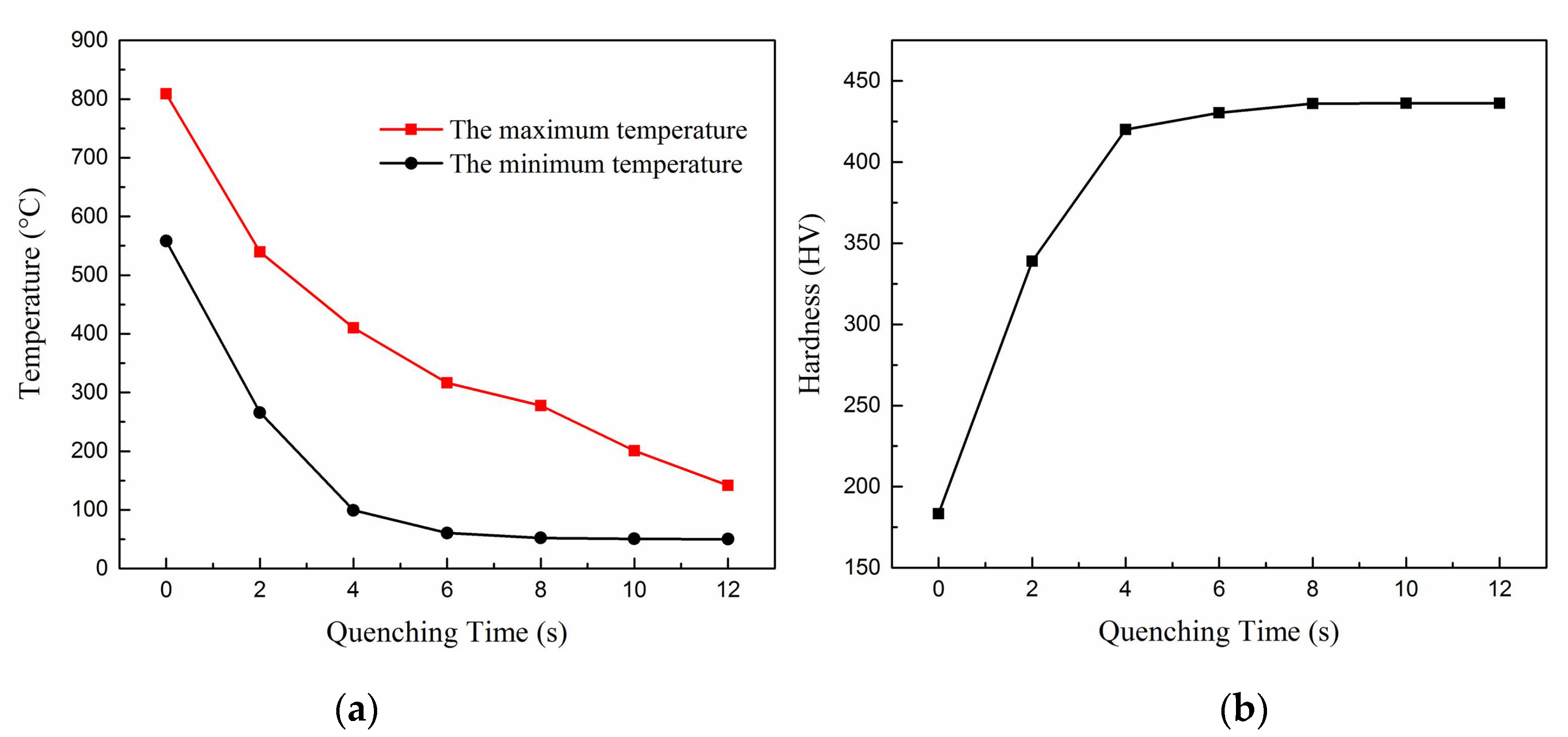
3.2. Effect of the Quenching Force and the Quenching Time

Another key factor of the hot stamping process is the quenching time with a given quenching force. On the one hand, the blank can release the internal stress to reduce the springback. On the other hand, a reasonable quenching force and enough quenching time lead to a very rapid cooling rate and promote the blank to transform from austenite to martensite. As HTC relies on the roughness of the tool and blank surfaces, it depends on the quenching force and usually it increases as the quenching force increases. Therefore, the quenching forces were selected from 0 to 4000 kN in 1000 kN intervals, the quenching time was 10 s, and the punch speed was 80 mm/s. Figure 5a shows the maximum temperature of the blank with different quenching forces after quenching, which occurred on the sidewall of the concave-convex. Under the same quenching time, with the increase of the quenching force, the maximum temperature of the blank was significantly decreased. When hot forming was completed, the blank and dies were still in contact and a slightly faster cooling rate was obtained. This could be caused by the actual contact situation between the blank and dies. The higher quenching force led to higher heat transfer efficiency. Figure 5b shows the temperature histories of a node from the bottom wall in the middle concave-convex of the blank during hot stamping. With the increase of the quenching force, the cooling rate at the same place was increased. Figure 5c shows the phase fractions of the blank with different quenching forces after quenching. When the quenching force was 0 kN, the blank contained a certain fraction of ferrite. When the quenching force was above 1000 kN, the fraction of martensite was stable and contained a few fractions of ferrite. Figure 5d shows the minimum hardness of the blank with different quenching forces after quenching. The hardness value reflected the variation of the microstructure. Since the martensite fraction was stable when the quenching force was 1000 kN, the increase of the minimum hardness at different quenching forces was small.
According to the heat transfer theory, when the two contact parts had a temperature difference, the longer contact time happened and the more heat exchange occurred. Therefore, the quenching times were selected from 0 to 12 s in 2 s intervals, the quenching force was 1000 kN, and the punch speed was 80 mm/s. Figure 6a shows the maximum and minimum temperature of the blank with different quenching times after quenching. With the increase of the quenching time, the temperature difference between the blank and dies first increased and then decreased. Since the martensite transformation occurred in a continuous cooling process, the number of martensite transformations stopped once the quenching was stopped. Thus, the maximum temperature of the blank should be below Mf, which means the quenching was completed. According to the FE simulation, after quenching for 8 s, the minimum temperature of the blank was a little higher than Mf. Thus, to guarantee the transformation was completed, the quenching time should have been over 8 s. When the quenching time was over 10 s, the maximum temperature of the blank was below Mf. Figure 6b shows the minimum hardness of the blank with different quenching times after quenching. A significant increase in hardness occurred across quenching times. When the quenching time was 0 s, the martensite transformation of the blank was insufficient and the hardness of the blank was low. When the quenching was over 10 s, the hardness of the blank was high and stabilized. Thus, it was concluded that the quenching force should be above 1000 kN and quenching time should be up to 10 s in these working conditions.

3.3. Comprehensive Results

According to the above discussion, when the punch speed was 80 mm/s, the quenching force was 1000 kN, and the quenching time was 10 s, the simulation results were as follows. Figure 7 shows the temperature distribution of the blank before and after the quenching stage. During hot stamping, the temperature dropped the most at both left and right side walls of the middle concave-convex of the blank. This was because this area was first contacted with the upper die and the heat losses were mainly from the heat conduction. Contrary to the heat forming, during the quenching stage, the temperature drop in the middle of the blank was slower than on both sides of the blank. After quenching, the maximum temperature of the blank was under 200 °C.
Figure 8 shows the temperature histories of eight nodes in the cross-section of the blank during hot stamping. Before 5.6 s, it was the time for pre-forming and transferring the blank from the furnace to the lower die. The temperature histories in this range were not analyzed. In the settling stage, it was the ram motion that lasted for 2 s. During the hot stamping stage (7.6–10.2 s), the temperature histories of each point were different because of the different contact situations between the upper die and the blank. During the quenching stage (10.2–20.2 s), the cooling rate was rapidly increased because the heat transfer happened with the given quenching force. When the temperature was dropped to Ms, the cooling rate was decreased due to the heat generated by the martensite transformation.
Figure 9a,b shows the thickness distribution of the blank before and after the indirect hot stamping. After forming at room temperature, the minimum thickness of the blank was 1.623 mm. After hot stamping, the minimum thickness of the blank was 1.619 mm. In this case, the blank was thinning due to the second forming during the hot stamping process. The thickness thinning mainly occurred in both left and right sidewalls of the concave-convex, and the maximum thinning occurred at the fillet of the concave-convex in the middle of the blank, which was caused by the large tensile stress that happened at this area during the hot stamping process. According to the studies, a 30% thinning ratio was the threshold in the hot stamping [22,23]. In this FE simulation, the maximum thinning ratio was 19.1%. In the area of sheet metal forming, the forming limit diagram (FLD) signifies an effective tool to characterize the formability of sheet metal materials during the forming process. The FLD reflects the strain state of materials before failure and has been extensively employed to analyze and predict rupture in the course of forming. Figure 9c shows the FLD diagram at the end of forming. There were no points in the red area that indicated that the beam part was in good formability and without cracks.

4. Analysis of Experimental Results of Hot Stamping

4.1. Hot Stamping Process

After the numerical simulation, the forming experiments of the beam part were performed for this paper. The experimental tools were composed of the upper die and the lower die, which were made of H13 hot work tool steel. The parameters of the experiment process were consistent with the numerical simulation, in which the punch speed was 80 mm/s, the quenching force was 1000 kN, and the quenching time was 10 s. Then, uniaxial tensile tests and microhardness tests were performed to measure the mechanical properties of the beam part. Tensile tests were performed using an MTS-810 (MTS Systems Corporation, Eden Prairie, MN, USA) materials test system and an MTS extensometer, which was conducted at a velocity of 1 mm/min. The specimens were cut as per GB/T 228-2010, and at least three specimens were tested in the same area to ensure repeatability of the test results. Figure 10 shows the hot stamping dies, locations of the tensile specimens that were cut from the beam part, and the geometry of tensile specimens. The microhardness was tested used an HXD-1000 microhardness tester (Shanghai, China) with an experimental force of 2 N and a loading time of 5 s. Then, 10 points of each microhardness test sample were measured and the average value was selected for description.
Figure 11a shows the engineering stress-strain curves from each tensile specimen. The tensile strength in different locations showed a little difference but, in general, the mechanical properties of the beam part were greatly improved after the hot stamping process. Figure 11b shows the hardness of the FE simulation and experimental results. The hardness values of the FE simulation were higher than the measured values. This may be due to the oxide layer generated during the hot stamping, which caused smaller heat transfer coefficients. Additionally, owing to the different temperature histories in different positions, the hardness values fluctuated in both simulation and experiment results.

4.2. Microstructure Analysis

The metallographic observations used a TESCAN VEGA3 scanning electron microscope (TESCAN, Brnocity, Czech Republic). The microstructures of the specimens at middle concave-convex (Figure 11b(4,5,7,8)) of the part are presented in Figure 12. The specimens were polished and etched with a 4% nitric acid alcohol solution for 20 s. It shows that the same phases with different fractions were generated in these four regions. The microstructures were composed of massive lath martensite and a little of ferrite, bainite, and residual austenite. As evident in Figure 12a,b, martensite in the over-plane regions (Figure 11b(4,8)) seemed more slender and uniformly distributed than the sidewall regions (Figure 11b(5,7)). The phase fraction in the left and right sidewall regions (Figure 12c,d) were basically the same. Besides martensite, multiple phases of bainite, ferrite, and residual austenite were found. The microstructure results were consistent with the results of the hardness values. Both left and right sidewall regions of the middle concave-convex could not be fully quenched due to the small quenching force and serious thinning on this area. So, the hardness values and martensite fraction were lower than the over-plane regions. Therefore, due to the inhomogeneity of the microstructure, some regions reflected the scattering in hardness values.

5. Conclusions

(1)
The FE simulation of the beam part manufactured by the indirect hot stamping process was discussed. After two-stages of pre-forming, the blank was in good formability and without visible cracks. During the hot stamping, the punch speed had to be higher than 80 mm/s to guarantee the blank was in full austenite stage before quenching. With the higher quenching force and enough quenching time, the blank obtained a more complete martensite transformation after quenching.
(2)
For the beam part, the reasonable parameters during the hot stamping were concluded: punch speed of 80 mm/s, quenching force of 1000 kN, and quenching time was up to 10 s. Based on the FE results, the maximum thinning ratio of the beam part was 19.1%, which satisfied the requirements of hot stamping.
(3)
According to the experiment results, the beam part was formed without failure after the indirect hot stamping process. Tests on mechanical properties were carried out and the results were in good consistency with the simulation results. The microstructures at different regions of the beam part were discussed and the over-plane regions had a better quenching effect than the sidewall regions. Furthermore, this paper confirmed that the FE simulation of the beam part was reliable.

Author Contributions

Software, Z.T.; formal analysis, H.X.; investigation, X.L.; writing—original draft, Z.T.; writing—review and editing, G.Y.; visualization, L.Z.; supervision, Z.G. All authors have read and agreed to the published version of the manuscript.

Funding

This work was financially supported by the National Natural Science Foundation of China (No. 51101072) and Technology Development Program of Jilin Province (No. 20160307015GX and No.3R2197212416).

Conflicts of Interest

The authors declare no conflict of interest in this work.

References

  1. Peng, Y.; Wang, G.; Zhu, T.; Pan, S.; Rong, Y. Dynamic Mechanical Behaviors of 6082-T6 Aluminum Alloy. Adv. Mech. Eng. 2013, 5, 878016. [Google Scholar]
  2. Lan, F.; Chen, J.; Lin, J. Comparative Analysis for Bus Side Structures and Lightweight Optimization. Proc. Inst. Mech. Eng. Part D J. Automob. Eng. 2004, 218, 1067–1075. [Google Scholar] [CrossRef]
  3. Su, R.Y.; Gui, L.J.; Fan, Z.J. Multi-Objective Optimization for Bus Body with Strength and Rollover Safety Constraints Based on Surrogate Models. Struct. Multidiscip. Optim. 2011, 44, 431–441. [Google Scholar] [CrossRef]
  4. Gauchia, A.; Diaz, V.; Boada, M.J.L.; Boada, B.L. Torsional Stiffness and Weight Optimization of a Real Bus Structure. Int. J. Automot. Technol. 2010, 11, 41–47. [Google Scholar] [CrossRef]
  5. Han, Y.; Xue, S.; Fu, R.; Lin, L.; Lin, Z.; Pei, Y.; Sun, H. Influence of Hydrogen Embrittlement on Impact Property and Microstructural Characteristics in Aluminum Alloy Weld. Vacuum 2020, 172, 109073. [Google Scholar] [CrossRef]
  6. Santos, M.C., Jr.; Machado, A.R.; Sales, W.F.; Barrozo, M.A.S.; Ezugwu, E.O. Machining of Aluminum Alloys: A Review. Int. J. Adv. Manuf. Technol. 2016, 86, 3067–3080. [Google Scholar] [CrossRef]
  7. Hwang, J.S.; Moon, J.H.; Kang, C.-G. Prediction of Springback During Indirect Hot Press Forming through Tensile Test with Simultaneous Cooling. Proc. Inst. Mech. Eng. Part B J. Eng. Manuf. 2013, 227, 1013–1022. [Google Scholar] [CrossRef]
  8. Han, X.H.; Wang, C.L.; Li, Y.Y.; Liu, G. Effects of Quenching and Partitioning Process on Mechanical Properties of Trip780 Steel. J. Iron Steel Res. Int. 2019, 26, 991–999. [Google Scholar] [CrossRef]
  9. Neugebauer, R.; Schieck, F.; Polster, S.; Mosel, A.; Rautenstrauch, A.; Schonherr, J.; Pierschel, N. Press Hardening—An Innovative and Challenging Technology. Arch. Civ. Mech. Eng. 2012, 12, 113–118. [Google Scholar] [CrossRef]
  10. Karbasian, H.; Tekkaya, A.E. A Review on Hot Stamping. J. Mater. Process. Technol. 2010, 210, 2103–2118. [Google Scholar] [CrossRef]
  11. Quan, G.-Z.; Zhan, Z.-Y.; Zhang, L.; Wu, D.-S.; Luo, G.-C.; Xia, Y.-F. A Study on the Multi-Phase Transformation Kinetics of Ultra-High-Strength Steel and Application in Thermal-Mechanical-Phase Coupling Simulation of Hot Stamping Process. Mater. Sci. Eng. A 2016, 673, 24–38. [Google Scholar] [CrossRef]
  12. Wang, W.; Zhang, L.; Guo, M.; Huang, L.; Wei, X. Non-Isothermal Deformation Behavior and Fe Simulation of Ultrahigh Strength Br1500hs Steel in Hot Stamping Process. Int. J. Adv. Manuf. Technol. 2016, 87, 2951–2965. [Google Scholar] [CrossRef]
  13. Cheng, W.; Zhang, H.; Fu, S.; Xie, H.; Tang, Z.; Zhu, Z. A Process-Performance Coupled Design Method for Hot-Stamped Tailor Rolled Blank Structure. Thin-Walled Struct. 2019, 140, 132–143. [Google Scholar] [CrossRef]
  14. Lee, M.-G.; Kim, S.-J.; Han, H.N. Finite Element Investigations for the Role of Transformation Plasticity on Springback in Hot Press Forming Process. Comput. Mater. Sci. 2009, 47, 556–567. [Google Scholar] [CrossRef]
  15. Cui, J.J.; Lei, C.X.; Xing, Z.W.; Li, C.F.; Ma, S.M. Predictions of the Mechanical Properties and Microstructure Evolution of High Strength Steel in Hot Stamping. J. Mater. Eng. Perform. 2012, 21, 2244–2254. [Google Scholar] [CrossRef]
  16. Tang, Z.M.; Gu, Z.W.; Jia, L.; Li, X.; Zhu, L.J.; Xu, H.; Yu, G. Research on Lightweight Design and Indirect Hot Stamping Process of the New Ultra-High Strength Steel Seat Bracket. Metals 2019, 9, 833. [Google Scholar] [CrossRef] [Green Version]
  17. Naderi, M.; Ketabchi, M.; Abbasi, M.; Bleck, W. Analysis of Microstructure and Mechanical Properties of Different High Strength Carbon Steels after Hot Stamping. J. Mater. Process. Technol. 2011, 211, 1117–1125. [Google Scholar] [CrossRef]
  18. Liu, H.S.; Liu, W.; Bao, J.; Xing, Z.W.; Song, B.Y.; Lei, C.X. Numerical and Experimental Investigation into Hot Forming of Ultra High Strength Steel Sheet. J. Mater. Eng. Perform. 2011, 20, 1–10. [Google Scholar] [CrossRef]
  19. Martin, D. Application of Kolmogorov–Johnson–Mehl–Avrami Equations to Non-Isothermal Conditions. Comput. Mater. Sci. 2010, 47, 796–800. [Google Scholar] [CrossRef]
  20. Åkerström, P.; Oldenburg, M. Austenite Decomposition During Press Hardening of a Boron Steel—Computer Simulation and Test. J. Mater. Process. Technol. 2006, 174, 399–406. [Google Scholar] [CrossRef]
  21. Jiang, C.; Shan, Z.D.; Zhuang, B.L.; Zhang, M.L.; Xu, Y. Hot Stamping Die Design for Vehicle Door Beams Using Ultra-High Strength Steel. Int. J. Precis. Eng. Manuf. 2012, 13, 1101–1106. [Google Scholar] [CrossRef]
  22. Bok, H.-H.; Lee, M.-G.; Pavlina, E.J.; Barlat, F.; Kim, H.-D. Comparative Study of the Prediction of Microstructure and Mechanical Properties for a Hot-Stamped B-Pillar Reinforcing Part. Int. J. Mech. Sci. 2011, 53, 744–752. [Google Scholar] [CrossRef]
  23. Choi, H.S.; Kim, B.M.; Nam, K.J.; Ha, S.Y.; Cha, S.H.; Kang, C.G. Development of Hot Stamped Center Pillar Using Form Die with Channel Type Indirect Blank Holder. Int. J. Automot. Technol. 2011, 12, 887–894. [Google Scholar] [CrossRef]
Figure 1. TV bracket model (a) and the typical section characteristics of the beam part (b).
Metals 10 01658 g001
Figure 2. Pressure- and gap-dependent heat transfer coefficient HTC (a) and stress-strain curves of 22MnB5 at different conditions (b).
Metals 10 01658 g002
Figure 3. Finite element FE models of indirect hot stamping: (a) first stage and (b) second stage of pre-forming (c) hot stamping.
Metals 10 01658 g003
Figure 4. Variation of the minimum temperature (a) and phase fractions with the punch speeds (b).
Metals 10 01658 g004
Figure 5. Variation of the maximum temperature (a), temperature histories (b), phase fractions (c), and minimum hardness with the quenching forces (d).
Metals 10 01658 g005
Figure 6. Variation of the temperature (a) and hardness with the quenching times (b).
Metals 10 01658 g006
Figure 7. Temperature distribution of the blank before (a) and after quenching stage (b).
Metals 10 01658 g007
Figure 8. Temperature histories at different positions during hot stamping.
Metals 10 01658 g008
Figure 9. Thickness distribution of the blank: pre-forming (a) after quenching (b) and forming limit diagram of the blank (c).
Metals 10 01658 g009
Figure 10. Hot stamping dies, (a) the locations, and (b) geometry of the tensile specimens (c) (unit: mm).
Metals 10 01658 g010
Figure 11. Engineering stress-strain curves (a) and hardness distribution of part (b).
Metals 10 01658 g011
Figure 12. Microstructures of the part at locations 4 (a), 5 (b), 7 (c), and 8 (d) as labeled in Figure 10b.
Metals 10 01658 g012
Table 1. Material properties and simulation conditions.
Material22MnB5
Thickness (mm)2
Young’s modulus (GPa)212
Poisson’s ratio0.3
Density (kg/m3)7.89 × 103
Simulation conditions
Punch speed (mm/s)40–140
Die temperature (°C)25
Friction coefficient0.3
Heat transfer coefficient for the tools (mW/mm2k)The function of pressure/gap
Heat transfer coefficient for ambient (mW/mm2k)20 °C-0.002
950 °C-0.075
Quenching force (kN)0–4000
Quenching time (s)0–12 s
Table 2. Chemical composition of the 22MnB5 steel (wt%).
CMnSiCrBP
0.22–0.251.2–1.40.2–0.30.11–0.20.002–0.004≤0.02
Publisher’s Note: MDPI stays neutral with regard to jurisdictional claims in published maps and institutional affiliations.

