Precipitation of M23C6 Secondary Carbide Particles in Fe-Cr-Mn-C Alloy during Heat Treatment Process


Abstract
:1. Introduction
2. Materials and Methods
3. Results and Discussion
4. Conclusions
Author Contributions
Funding
Acknowledgments
Conflicts of Interest
References
- Tabrett, C.P.; Sare, I.R.; Ghomashchi, M.R. Microstructure-property relationships in high chromium white iron alloys. Int. Mater. Rev. 1996, 41, 59–82. [Google Scholar] [CrossRef]
- Wiengmoon, A. Carbides in high chromium cast irons. Naresuan Univ. Eng. J. 2011, 6, 64–71. [Google Scholar] [CrossRef]
- Wieczerzak, K.; Bała, P.; Stępień, M.; Cios, G.; Kozieł, T. The characterization of cast Fe-Cr-C alloy. Arch. Metall. Mater. 2015, 60, 779–782. [Google Scholar] [CrossRef] [Green Version]
- Gonzalez-Pociño, A.; Alvarez-Antolin, F.; Asensio-Lozano, J. Influence of thermal parameters related to destabilization treatments on erosive wear resistance and microstructural variation of white cast iron containing 18% Cr. application of design of experiments and rietveld structural analysis. Materials 2019, 12, 3252. [Google Scholar] [CrossRef] [PubMed] [Green Version]
- Jia, X.; Huang, Y.; Zuo, X.; Liu, Y.; Chen, N.; Rong, Y. High hardness-toughness and wear resistance of white cast iron treated by a multicycle quenching-partitioning-tempering process. Heat Treat. Surf. Eng. 2019, 1, 57–62. [Google Scholar] [CrossRef] [Green Version]
- Nayak, P.U.; Guitar, A.M.; Mücklich, F. A Comparative study on the influence of chromium on the phase fraction and elemental distribution in as-cast high chromium cast irons: simulation vs. experimentation. Metals 2019, 10, 30. [Google Scholar] [CrossRef] [Green Version]
- Sapate, S.G.; Rama Rao, A.V. Effect of carbide volume fraction on erosive wear behaviour of hardfacing cast irons. Wear 2004, 256, 774–786. [Google Scholar] [CrossRef]
- Fan, C.; Chen, M.-C.; Chang, C.-M.; Wu, W. Microstructure change caused by (Cr,Fe)23C6 carbides in high chromium Fe–Cr–C hardfacing alloys. Surf. Coat. Technol. 2006, 201, 908–912. [Google Scholar] [CrossRef]
- Abdel-Aziz, K.; El-Shennawy, M.; Omar, A.A. Microstructural characteristics and mechanical properties of heat treated high-Cr white cast iron alloys. Int. J. Appl. Eng. Res. 2017, 12, 4675–4686. [Google Scholar]
- Davis, J.R. Metallurgy and properties of high alloy white irons. In ASM Specially Hand Book: Cast Irons; ASM International: Cleveland, OH, USA, 1996; pp. 107–130. [Google Scholar]
- Gundlach, R.B. High alloy white irons. In ASM Hand Book, Casting, 4th ed.; ASM International: Cleveland, OH, USA, 1998; pp. 679–685. [Google Scholar]
- Wang, J.; Li, C.; Liu, H.; Yang, H.; Shen, B.; Gao, S.; Huang, S. The precipitation and transformation of secondary carbides in a high chromium cast iron. Mater. Charact. 2006, 56, 73–78. [Google Scholar] [CrossRef]
- Liu, Q.; Shibata, H.; Hedström, P.; Jönsson, P.G.; Nakajima, K. Dynamic precipitation behavior of secondary M7C3 carbides in Ti-alloyed high chromium Cast Iron. ISIJ Int. 2013, 53, 1237–1244. [Google Scholar] [CrossRef] [Green Version]
- Ma, S.; Xing, J.; He, Y.; Li, Y.; Huang, Z.; Liu, G.; Geng, Q. Microstructure and crystallography of M7C3 carbide in chromium cast iron. Mater. Chem. Phys. 2015, 161, 65–73. [Google Scholar] [CrossRef]
- Wieczerzak, K.; Bala, P.; Dziurka, R.; Tokarski, T.; Cios, G.; Koziel, T.; Gondek, L. The effect of temperature on the evolution of eutectic carbides and M7C3 → M23C6 carbides reaction in the rapidly solidified Fe-Cr-C alloy. J. Alloys Compd. 2017, 698, 673–684. [Google Scholar] [CrossRef]
- Tabrett, C.P.; Sare, I.R. Effect of high temperature and sub-ambient treatments on the matrix structure and abrasion resistance of a high-chromium white iron. Scr. Mater. 1998, 38, 1747–1753. [Google Scholar] [CrossRef]
- ASTM International. A 532/A 532M—Standard Specification for Abrasion-Resistant Cast Irons; ASTM International: West Conshohocken, PA, USA, 2003; pp. 1–4. [Google Scholar]
- Gundlach, R.B.; Doane, D.V. Alloy Cast Irons. In ASM Handbook—Properties and Selection: Irons, Steels, and High Performance Alloys; ASM International: Cleveland, OH, USA, 2009; Volume 1, pp. 222–269. [Google Scholar]
- Saunders, N.; Guo, U.K.Z.; Li, X.; Miodownik, A.P.; Schillé, J.P. Using JMatPro to model materials properties and behavior. JOM 2003, 55, 60–65. [Google Scholar] [CrossRef]
- Guo, Z.; Saunders, N.; Miodownik, P.; Schille, J.-P. Modelling phase transformations and material properties critical to the prediction of distortion during the heat treatment of steels. Int. J. Microstruct. Mater. Prop. 2009, 4, 187–195. [Google Scholar] [CrossRef]
- Asensio, J.; Pero-Sanz, J.A.; Verdeja, J.I. Microstructure selection criteria for cast irons with more than 10 wt.% chromium for wear applications. Mater. Charact. 2002, 49, 83–93. [Google Scholar] [CrossRef]
- Zhou, Y.F.; Qin, G.K.; Jiang, P.J.; Wang, S.F.; Qi, X.W.; Xing, X.L.; Yang, Q.X. Dry sliding wear behavior of (Cr, Fe)7C3-γ(Cr, Fe) metal matrix composite (MMC) coatings: the influence of high volume fraction (Cr, Fe)7C3 carbide. Tribol. Lett. 2018, 66, 108. [Google Scholar] [CrossRef]
- Huggett, P.; Ben-Nissan, B. Development of a low melting point white cast iron for use in composite alloy manufacture. Mater. Forum 2007, 31, 16–23. [Google Scholar]
- Zhi, X.; Xing, J.; Gao, Y.; Fu, H.; Peng, J.; Xiao, B. Effect of heat treatment on microstructure and mechanical properties of a Ti-bearing hypereutectic high chromium white cast iron. Mater. Sci. Eng. A 2008, 487, 171–179. [Google Scholar] [CrossRef]
- Powell, G.L.F.; Bee, J.V. Secondary carbide precipitation in an 18 wt%Cr-1 wt% Mo white iron. J. Mater. Sci. 1996, 31, 707–711. [Google Scholar] [CrossRef]


| Element | Fe | C | Si | Mn | P | S | Cr | Mo | Ni | Cu | Al |
|---|---|---|---|---|---|---|---|---|---|---|---|
| wt.% | Bal. | 2.08 | 0.284 | 1.30 | 0.093 | 0.058 | 12.1 | 0.046 | 0.270 | 0.102 | 0.05 |
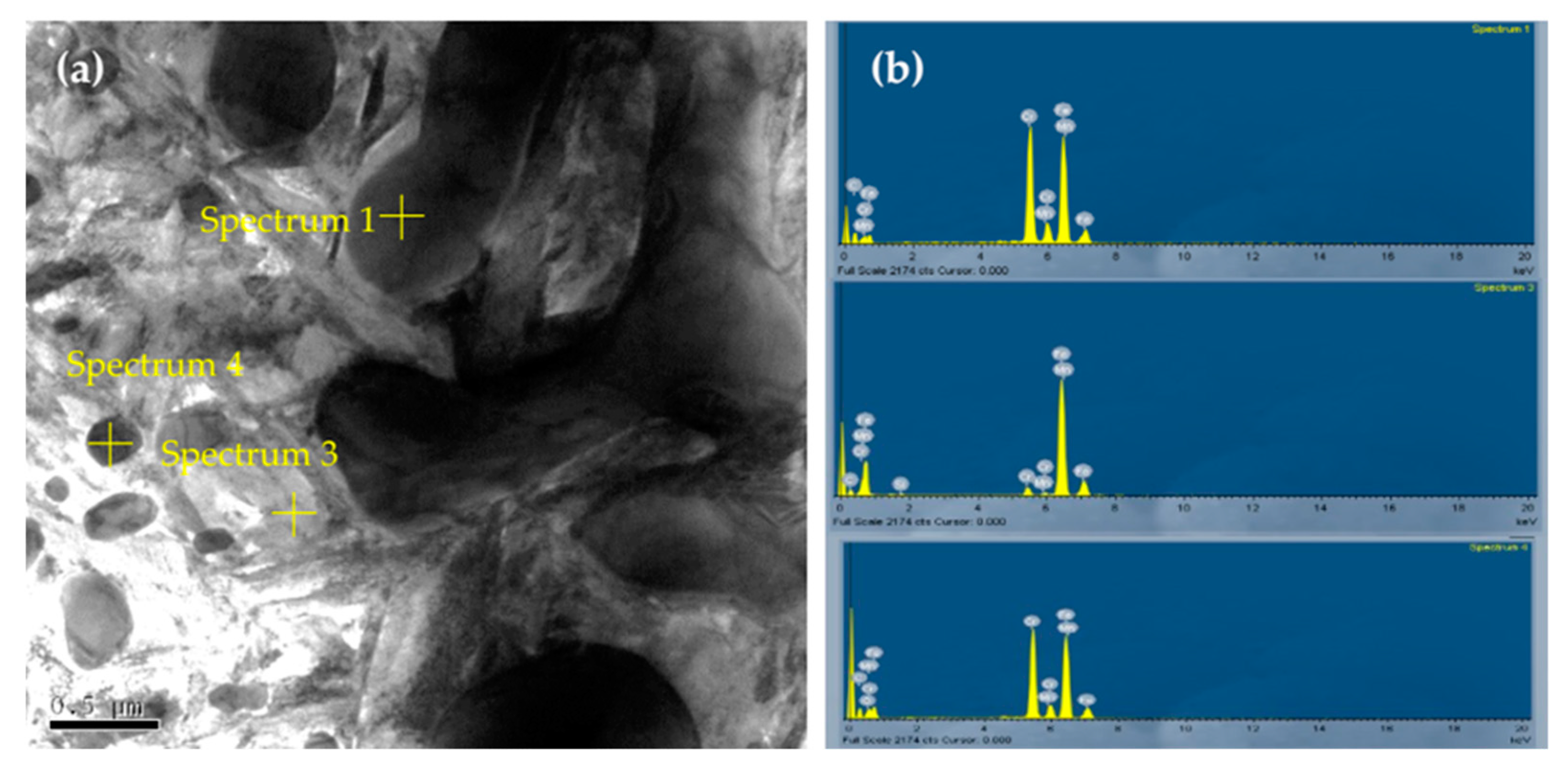
| Spectrum | Atomic (%) | Phase | |||||||||
|---|---|---|---|---|---|---|---|---|---|---|---|
| Mn | Si | O | C | Cr | Fe | Cr/Fe | Cr/C | Fe/C | (Cr+Fe)/C | ||
| 1 | 1.66 | - | - | 17.71 | 41.39 | 39.22 | 1.05 | 2.33 | 2.21 | 4.55 | M7C3 |
| 3 | 1.21 | 1.25 | - | 15.72 | 4.79 | 77.02 | 0.06 | 0.30 | 4.90 | ||
| 4 | 1.13 | - | 3.09 | 20.33 | 37.98 | 37.46 | 1.01 | 1.87 | 1.84 | 3.71 | M23C6 |
© 2020 by the authors. Licensee MDPI, Basel, Switzerland. This article is an open access article distributed under the terms and conditions of the Creative Commons Attribution (CC BY) license (http://creativecommons.org/licenses/by/4.0/).
Share and Cite
Oanh, N.T.H.; Viet, N.H. Precipitation of M23C6 Secondary Carbide Particles in Fe-Cr-Mn-C Alloy during Heat Treatment Process. Metals 2020, 10, 157. https://doi.org/10.3390/met10020157
Oanh NTH, Viet NH. Precipitation of M23C6 Secondary Carbide Particles in Fe-Cr-Mn-C Alloy during Heat Treatment Process. Metals. 2020; 10(2):157. https://doi.org/10.3390/met10020157
Chicago/Turabian StyleOanh, Nguyen Thi Hoang, and Nguyen Hoang Viet. 2020. "Precipitation of M23C6 Secondary Carbide Particles in Fe-Cr-Mn-C Alloy during Heat Treatment Process" Metals 10, no. 2: 157. https://doi.org/10.3390/met10020157
APA StyleOanh, N. T. H., & Viet, N. H. (2020). Precipitation of M23C6 Secondary Carbide Particles in Fe-Cr-Mn-C Alloy during Heat Treatment Process. Metals, 10(2), 157. https://doi.org/10.3390/met10020157