2. Materials and Methods
A diode-pumped solid-state ps-pulsed laser (Atlantic 355-60, Ekspla, Vilnius, Lithuania), emitting at 532 nm a maximum power of 38 W at 400 kHz, was used for the LIFT process. Laser pulses with a duration of 13 ps and energies in the range of 5 to 20 µJ were used. Laser pulse energy was measured after the optical path using a thermal sensor with an accuracy of 3%.
In the first part of the work, a computer-controlled X-Y linear translation stage was used for displacing both the donor and the acceptor substrates with respect to the laser beam. When printing lines, the stage moving speed was fixed at 60 mm/s and the laser repetition rate was varied from 400 to 2000 Hz. The pulse-to-pulse distance or pitch distance between single successive laser pulses is directly determined by dividing the stage moving speed by the laser pulse repetition rate. Hence, the pitch distances varied from 30 µm to 150 µm. The sample started moving prior to firing the laser, avoiding any acceleration effect at the beginning or end of the line. The pitch distance and the number of laser pulses were adjusted for printing lines 3 cm long.
In this case, the optical path was comprised of a 5X beam expander (Sill Optics GmbH & Co. KG, Wendelstein, Germany) and a fixed focusing lens (Linos Focus-Ronar, Qioptiq Photonics GmbH & Co. KG, Goettingen, Germany) with a focal length of 58 mm. The laser beam was focused (beam waist ω0 = 5 µm and laser spot size of ≈ 78.5 µm2) on the interface between the transparent donor substrate and the film of the material to be transferred. The Gaussian peak fluences ranged from 12.7 to 51.0 J/cm2.
In the final part of the work, the sample position was fixed and the laser beam was scanned along the sample at high speed using a polygon scanner (LSE170, Next Scan Technology, Evergem, Belgium). In this case, the optical focusing system had a focal distance of 190 mm, which led to a beam waist at focus (ω0) of 12 µm (laser spot size of ≈452 µm2 and Gaussian peak fluences from 2.2 to 8.8 J/cm2).
A commercial silver paste (Solamet PV17F, DuPont, Bristol, UK) was used as the donor material. The silver paste shows non-Newtonian thixotropic fluid behavior. Hence, the silver paste was gently stirred for 5 min before using it, to attain the equilibrium viscosity. The equilibrium viscosity was measured with a cone spindle and plate viscometer (HBDV-II+PCP, Brookfield Engineering Laboratories Inc., Stoughton, MA, USA), obtaining a value of 250 ± 30 Pa·s (cone spindle CPE-52, shear rate 5 s
−1, 23 °C). The paste was then deposited onto standard microscope glass slides, which acted as donor substrates, using a commercial coater (K101 Control Coater, RK Print Coat Instruments Ltd., Royston, UK). The thickness of the donor layer was measured in each donor sample both before and after the LIFT experiments. A c-Si polished wafer was used as the acceptor substrate. The gap distance between the donor and the acceptor was achieved by sticking commercial polyimide tape (Kapton, DuPont) onto the donor substrate. The morphology of the transferred paste and the holes left on the donor substrate after the LIFT process was characterized using a confocal microscope (DCM3D, Leica Microsystems, Wetzlar, Germany). More details on the experimental setup can be found elsewhere [
12,
14,
15,
16].
4. Discussion
The transfer mechanisms of LIFT are quite different when using Newtonian liquids or low viscosity inks as a donor as compared with using a paste with a high viscosity and comprised of Ag particles with sizes in the order of 1 to 4 µm [
14]. In the latter case, it has been shown that the transfer mechanisms depend on the relationship between laser pulse energy, donor film thickness, and gap distances. When using pulse energies that are too high for a determined combination of donor thickness and gap distance, explosive transfer occurs and the paste splashes on the acceptor. If the energy is lower, typically the resulting voxels consist of small clusters of paste. Only when the donor film thickness is similar to the gap with a pulse energy near the transfer threshold is it possible to transfer a well-defined single dot of paste with a large aspect-ratio (concrete-dot transfer). In this situation, the protruding jet touches the acceptor substrate before disaggregation forming a stable paste pillar between the donor and acceptor. When the donor is lifted, the pillar breaks and the printed voxel remains on the surface of the acceptor substrate.
In this work, the best single voxel transfer, i.e., the dot with the largest aspect ratio (0.09), is obtained when the donor film thickness is similar to the gap distance. The voxel consists of a single dot of paste without disaggregation in several clusters. However, the distribution of paste is not homogenous. Thus, the transfer mechanism should be in the limit of the conditions for the formation of a stable pillar. Using higher or lower pulse energies lead to cluster transfer or no transfer, respectively. These conditions have been selected as a starting point for printing lines.
In the case of lines, a strong influence of the separation of the subsequent dots (pitch distance) on the morphology of the line has been shown. It is worth noting that the diameter of the laser focused beam (≈10 µm) is one order of magnitude smaller than the diameter of the hole remaining and the diameter of the voxel transferred (both in the order of 100 µm) and smaller than the pitch distance (30 to 150 µm). Therefore, when the term overlapping is used, it refers to the overlapping of the imprint left in the donor (hole or not) or to the overlapping of the printed voxels.
In the case of the longest pitch distance (150 µm), it should be long enough to avoid any interaction between subsequent dots and, then, the voxels should be similar to the static process. However, the voxels consist of several clusters instead of a well-define single dot of paste. In the case of the shortest pitch distances (shorter than 60 µm), the interaction effect is even more acute, i.e., the shorter the pitch distance the less amount of material transferred. The beginning of the line represents that the very first pulse is the same regardless of the pitch distance. These first voxels always have the same cluster structure. Similar overlapping effects have also been described by Sopeña et al. [
13] for Ag inks with viscosity one order of magnitude smaller than the Ag paste used in the present work.
This behavior can be explained in terms of the transfer mechanism for high viscosity pastes [
14] as follows: The very first pulse found fresh material and its transfer mechanism is that of the static situation, the protruding pillar expands, and a stable pillar is formed. Once the pillar is formed, the next laser pulse is fired. Time between pulses is in the order of several ms, longer than the typical times needed for the displacement of the paste, the formation of the protruding jet, or the formation of the stable pillar (in the order of µs).
When a second laser pulse is fired at a long pitch, but short enough to see overlapping between printed voxels (pitch distances of 150 or 100 µm), the expanding vapor bubble affects the delicate equilibrium of the previous system bubble pillar, breaking the stable pillar, and projecting clusters of paste onto the acceptor.
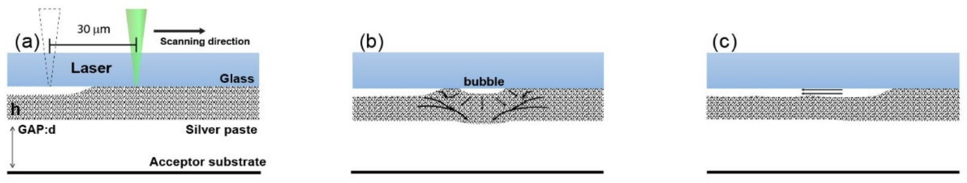
When the pitch distance is shorter (pitch distances of 30 and 60 µm), the paste wall between the bubble and the previous hole is very thin. The large pressure generated inside the bubble could break that wall, reducing the pressure, and thus reducing the amount of material pushed to the acceptor substrate. Although there is no transfer, there is movement of paste inside the film, leaving a void volume inside the film. The gas bubbles induced by subsequent pulses reduce their pressure in the same way, enlarging the void volume, and forming a draught tunnel along the laser scanning trace in the film, as shown schematically in
Figure 6.
To verify the proposed mechanism, the donor was characterized again by optical microscopy, but in this case through the glass slide side using a long working distance objective.
Figure 7 shows images focused on the film-glass interface of the middle part of laser scanning traces left in the donors with pitch distance of 100 µm, 80 µm, 60 µm, and 30 µm. In the case of pitch distance 100 µm (
Figure 7a), individual holes are observed. When the pitch distance is reduced to 80 µm (
Figure 7b), instead of holes, craters appear near the film-glass interface, i.e., the crater formed on the paste surface and the crater left on the film-glass interface are not connected. And the diameter of these holes is smaller than the ones with pitch distance of 100 µm.
This can be caused by the overlapping of the two successive generated bubbles. When the bubble expands to the adjacent crater, its pressure decreases, and it is not high enough for forward transferring of the material. With pitch distances of 60 µm and 30 µm (
Figure 7c,d), the overlapping effect becomes more evident. The shallow groove formed on the film-glass interface implies the overlapping of the bubbles, which finally forms the tunnel in the donor.
Continuous lines were obtained only by increasing the donor film thickness (40 µm), while maintaining the gap distance. In this case, the laser pulse energy must also be increased because the mass of silver paste to be transferred is larger. The voxel morphology using low pulse energies yields similar results as those obtained with a thinner donor film (30 µm), although the transfer mechanism is different. In the thicker donor film case, the holes remaining in the donor are not homogeneous and the pillar is not stable and disaggregates in several clusters. By increasing the laser pulse energy, it is possible to move more material and form a stable pillar. Because the donor film is thicker, the expansion velocity of the jet is smaller than in the case of the thinner donor film. The walls formed between successive bubbles are also thicker, and thus interference between pulses is more unlikely. The pillar remains stable until the donor is lifted. Only at this moment does the pillar break, pulling the material from the donor to the acceptor, leaving a clean grove in the donor film. The printed line is continuous only at the higher pulse energies, which move enough material to homogeneously overlap the voxels.
Previous results have been related to those observed in multipulse LIFT of low viscosity fluids [
10]. In that case, there is an effect of fluid movement, filling up the void after the printing event. Therefore, there is a temporal limit for printing successive voxels, i.e., the time needed for the fluid to move [
18]. This limit can be overcome by using high repetition lasers [
11,
19]. If the time between pulses is short enough as compared with the beam displacement, the cavitation bubbles generated in the fluid by successive pulses interact and merge, the transferred jets are linked, and a continuous line can be printed.
When the viscosity increases, the time that the fluid needs to fill the hole increases, the column between the donor and acceptor remains, and a spatial effect arises [
13]. In the present work, the viscosity is so high that there is no fluid movement after the laser pulse and the void remains for a very long times, and thus the high viscosity paste LIFT can be understood as a “frozen” state of the low viscosity ink LIFT. The merge of the cavitation bubbles forming a continuous channel (
Figure 7) is now undesirable. The limitation is not temporal but spatial. Successive voxels should be printed at a threshold pitch distance, short enough for good overlapping but long enough to avoid interactions between successive voids. This result is positive in the sense that it is possible to escalate the process for printing at a very high speed, if just the laser repetition rate and the scanning speed are increased in the same factor.
Author Contributions
Conceptualization, D.M.-M., M.M., and C.M.; methodology, D.M.-M.; validation, D.M.-M., Y.C., and M.M.; formal analysis, D.M.-M. and Y.C.; investigation, Y.C.; resources, D.M.-M. and Y.C.; data curation, D.M.-M.; writing—original draft preparation, Y.C.; writing—review and editing, D.M.-M., M.M., and C.M.; visualization, D.M.-M. and Y.C.; supervision, M.M.; project administration, M.M. and C.M.; funding acquisition, M.M. and C.M. All authors have read and agreed to the published version of the manuscript.
Funding
This research was funded by the EUROPEAN COMISSION APPOLO FP7-2013-NMP-ICT-FOF. 609355, the Spanish MINECO projects SIMLASPV-MET (ENE2014-58454-R), the HELLO (ENE2013-48629-C4-3-R) and CHENOC (ENE2016-78933-C4-4-R), and the Comunidad de Madrid Project ADITIMAT-CM (S2018/NMT-4411).
Conflicts of Interest
The authors declare no conflict of interest.
References
- Arnold, C.B.; Serra, P.; Piqué, A. Laser Direct-Write Techniques for Printing of Complex Materials. MRS Bull. 2007, 32, 23–32. [Google Scholar] [CrossRef] [Green Version]
- Piqué, A.; Auyeung, R.C.Y.; Kim, H.; Charipar, N.A.; Mathews, S.A. Laser 3D micro-manufacturing. J. Phys. D Appl. Phys. 2016, 49, 223001. [Google Scholar] [CrossRef]
- Auyeung, R.C.Y.; Kim, H.; Mathews, S.; Piqué, A. Laser forward transfer using structured light. Opt. Express 2015, 23, 422–430. [Google Scholar] [CrossRef] [PubMed]
- Visser, C.W.; Pohl, R.; Sun, C.; Römer, G.W.; Huis in ‘t Veld, B.; Lohse, D. Toward 3D Printing of Pure Metals by Laser-Induced Forward Transfer. Adv. Mater. 2015, 27, 4087–4092. [Google Scholar] [CrossRef] [PubMed] [Green Version]
- Wang, J.; Auyeung, R.C.Y.; Kim, H.; Charipar, N.A.; Piqué, A. Three-Dimensional Printing of Interconnects by Laser Direct-Write of Silver Nanopastes. Adv. Mater. 2010, 22, 4462–4466. [Google Scholar] [CrossRef] [PubMed]
- Zenou, M.; Sa’Ar, A.; Kotler, Z. Laser jetting of femto-liter metal droplets for high resolution 3D printed structures. Sci. Rep. 2015, 5, 17265. [Google Scholar] [CrossRef] [PubMed]
- Hennig, G.; Baldermann, T.; Nussbaum, C.; Rossier, M.; Brockelt, A.; Schuler, L.; Hochstein, G. Lasersonic® LIFT Process for Large Area Digital Printing. J. Laser Micro Nanoeng. 2012, 7, 299–305. [Google Scholar] [CrossRef]
- Serra, P.; Piqué, A. Laser-Induced Forward Transfer: Fundamentals and Applications. Adv. Mater. Technol. 2019, 4, 1800099. [Google Scholar] [CrossRef] [Green Version]
- Morales, M.; Munoz-Martin, D.; Marquez, A.; Lauzurica, S.; Molpeceres, C. Laser-Induced Forward Transfer Techniques and Applications. In Advances in Laser Materials Processing: Technology, Research and Applications; Lawrence, J.R., Ed.; Woodhead Publishing: Cambridge, UK, 2018; pp. 339–379. ISBN 9780081012536. [Google Scholar]
- Brasz, C.F.; Yang, J.H.; Arnold, C.B. Tilting of adjacent laser-induced liquid jets. Microfluid. Nanofluid. 2014, 18, 185–197. [Google Scholar] [CrossRef]
- Puerto, D.; Biver, E.; Alloncle, A.P.; Delaporte, P. Single step high-speed printing of continuous silver lines by laser-induced forward transfer. Appl. Surf. Sci. 2016, 374, 183–189. [Google Scholar] [CrossRef]
- Chen, Y. Desarrollo de Procesos para Formación de Contactos con Láser para Módulos Thin Film CIGS para Aplicaciones Fotovoltaicas; Universidad Politécnica de Madrid: Madrid, Spain, 2016. [Google Scholar] [CrossRef] [Green Version]
- Sopeña, P.; Fernández-Pradas, J.M.; Serra, P. Laser-induced forward transfer of conductive screen-printing inks. Appl. Surf. Sci. 2020, 507, 145047. [Google Scholar] [CrossRef]
- Munoz-Martin, D.; Brasz, C.F.; Chen, Y.; Morales, M.; Arnold, C.B.; Molpeceres, C. Laser-induced forward transfer of high-viscosity silver pastes. Appl. Surf. Sci. 2016, 366, 389–396. [Google Scholar] [CrossRef]
- Morales, M.; Chen, Y.; Munoz-Martin, D.; Lauzurica, S.; Molpeceres, C. High volume transfer of high viscosity silver pastes using laser direct-write processing for screen printing of c-Si cells. Proc. SPIE 2015, 9351. [Google Scholar] [CrossRef]
- Munoz-Martin, D.; Chen, Y.; Morales, M.; Molpeceres, C.; Grishin, M. Metallization of Silicon Solar Cells Using ps- and ns-Pulsed Lasers. In Proceedings of the 31st European Photovoltaic Solar Energy Conference and Exhibition, Hamburg, Germany, 14–18 September 2015; pp. 962–964. [Google Scholar]
- Chen, Y.; Munoz-Martin, D.; Morales, M.; Molpeceres, C.; Sánchez-Cortezon, E.; Murillo-Gutierrez, J. Laser induced forward transfer of high viscosity silver paste for new metallization methods in photovoltaic and flexible electronics industry. Phys. Procedia 2016, 83, 204–210. [Google Scholar] [CrossRef] [Green Version]
- Turkoz, E.; Morales, M.; Kang, S.Y.; Perazzo, A.; Stone, H.A.; Molpeceres, C.; Arnold, C.B. Laser-induced forward transfer from healing silver paste films. Appl. Phys. Lett. 2018, 113, 221601. [Google Scholar] [CrossRef] [Green Version]
- Biver, E.; Rapp, L.; Alloncle, A.P.; Delaporte, P. Multi-jets formation using laser forward transfer. Appl. Surf. Sci. 2014, 302, 153–158. [Google Scholar] [CrossRef]
Figure 1.
Best voxel printed using a single laser pulse (pulse energy 8.3 µJ, donor film thickness 30 µm, and gap distance 50 µm): (a) microscope image, (b) false color confocal microscope image, and (c) height profile.
Figure 2.
False color confocal images of (b) donor film and (d) acceptor substrate of the middle part of a printed line using 8.3 µJ pulse energy, 30 µm donor film thickness, 50 µm gap distance, and different pitch distances: (from left to right) 150 µm, 100 µm, 80 µm, and 60 µm. The laser pulse train (a) and cross-sectional profile (c) of both holes left in the donor and the transferred pastes are also shown. Dash line indicates the position of the glass-paste interface. Laser beam scanning direction is from right to left.
Figure 3.
False color confocal images of (b) donor film and (d) acceptor substrate of the beginning of a printed line using 8.3 µJ pulse energy, 30 µm donor film thickness, 50 µm gap distance, and different pitch distances: (from left to right) 150 µm, 100 µm, 80 µm, and 60 µm. The laser pulse train (a) and cross-sectional profile (c) of both holes left in the donor and the transferred pastes are also shown. Dash line indicates the position of the glass-paste interface. Laser beam scanning direction is from right to left.
Figure 4.
False color confocal images of (b) donor film and (d) acceptor substrate of the middle part of a printed line using 40 µm donor film thickness, 50 µm gap distance, 100 µm pitch distance, and different laser pulse energies: (from left to right) 5.6, 8.3, 9.7, and 11.2 µJ. The laser pulse train (a) and cross-sectional profile (c) of both holes left in the donor and the transferred pastes are also shown. Dash line indicates the position of the glass-paste interface. Laser beam scanning direction is from right to left.
Figure 5.
Cross-section profile of the printed line with 40 µm donor film thickness, 50 µm gap distance, and laser pulse energy of 11.2 µJ.
Figure 6.
Schematic of the laser pulse overlapping effect with a short pitch distance (30 µm) on the donor substrate in the LIFT process: (a) pulse laser focused onto the glass-paste interface, (b) gas bubble generation and paste movement without transference, and (c) formation of a draught tunnel due to interconnection of the overlapped pulses
Figure 7.
Top view microscope images through the glass of the middle parts of laser scanning trace using 8.3 µJ pulse energy, 30 µm donor film thickness, 50 µm gap distance, and different pitch distances: (a) 100, (b) 80, (c) 60, and (d) 30 µm.
Figure 8.
Microscope images of silver lines printed at 59.8 m/s using 50 µm donor film thickness, 50 µm gap distance, and two different laser pulse energies: (a) 6.9 and (b) 18.1 µJ.
© 2020 by the authors. Licensee MDPI, Basel, Switzerland. This article is an open access article distributed under the terms and conditions of the Creative Commons Attribution (CC BY) license (http://creativecommons.org/licenses/by/4.0/).


