Article

Kinetic Models for the in Situ Reaction between Cu-Ti Melt and Graphite

State Key Laboratory of Advanced Metallurgy, University of Science and Technology Beijing, Xueyuan Road No.30, Haidian District, Beijing 100083, China
*
Author to whom correspondence should be addressed.
Metals 2020, 10(2), 267; https://doi.org/10.3390/met10020267
Submission received: 16 January 2020 / Revised: 14 February 2020 / Accepted: 17 February 2020 / Published: 18 February 2020

Abstract

:
The in situ reaction method for preparing metal matrix composites has the advantages of a simple process, good combination of the reinforcing phase and matrix, etc. Based on the mechanism of forming TiCx particles via the dissolution reaction of solid carbon (C) particles in Cu-Ti melt, the kinetic models for C particle dissolution reaction were established. The kinetic models of the dissolution reaction of spherical, cylindrical, and flat C source particles in Cu-Ti melt were deduced, and the expressions of the time for the complete reaction of C source particles of different sizes were obtained. The mathematical relationship between the degree of reaction of C source and the reaction time was deduced by introducing the shape factor. By immersing a cylindrical C rod in a Cu-Ti melt and placing it in a super-gravity field for the dissolution reaction, it was found that the super-gravity field could cause the precipitated TiCx particles to aggregate toward the upper part of the sample under the action of buoyancy. Therefore, the consuming rate of the C rod was significantly accelerated. Based on the flat C source reaction kinetic model, the relationship between the floating speed of TiCx particles in the Cu-Ti melt and the centrifugal velocity (or the coefficient of super-gravity G) was derived. It was proven that, when the centrifugal velocity exceeded a critical value, the super-gravity field could completely avoid the accumulation behavior of TiCx particles on the surface of the C source, thereby speeding up the formation reaction of TiCx. The goal of this study is to better understand and evaluate the generating process of TiCx particles, thus finding possible methods to increase the reaction efficiency

Graphical Abstract

1. Introduction

TiCx powder has a high melting point, corrosion resistance, and hardness (micro hardness up to 3000 kg/mm2), which is just lower than diamond. It is a high-quality basic material for cutting tools, wear-resistant parts, hard alloys, etc., and it has important application value in the field of high-mechanical-property material preparation [1]. However, its synthesis conditions are very harsh [2,3], as the carbothermal reduction method with TiO2 powder, which is commonly used in the industry, requires a high synthesis temperature (1700–2100 °C) and long reaction time of 10–24 h. Due to the limitation on mass transfer conditions of solid-solid reactions, the products often contain unreacted C and Ti. Therefore, the synthesized TiCx powder has a wide range of particle size distribution, which demands an additional process of ball milling. The direct carbonization method [4] uses Ti powder and C powder to generate TiCx. The reaction takes 5–20 h, and the reaction process is difficult to control. The reactants are severely prone to agglomeration, and fine grinding is required to prepare fine-sized TiCx powder. In order to obtain a purer product, the fine powder after ball milling needs to be chemically purified. In addition, due to the high price of Ti metal powder, the cost of synthesizing TiCx is also high with this method. The self-propagating high-temperature synthesis (SHS) [5,6,7] method uses the reaction heat of the TiCx formation reaction to keep the reaction going. This synthesis method requires high-purity and fine Ti powder as raw materials [8,9], and the yield is limited. The reaction of the ball milling method [10,11,12] uses Ti powder and C powder to generate TiCx via their combination reaction under the action of mechanical energy during the ball milling process. Because the reaction process is very slow, this method is usually used to produce nanoscale TiCx powder on a small scale. Other methods for preparing TiCx powder, such as the chemical vapor deposition method and the microwave synthesis method, all have some defects, which cannot meet the needs of industrial production.
In view of the above problems, the authors herein propose a method for preparing TiCx powder via the solid-liquid reaction between Cu-Ti melt and dissolvable solid C coupled with super-gravity separation. The solid-liquid in situ reaction between solid C and Cu-Ti melt was firstly used to generate TiCx particles [13,14,15]. After super-gravity filtration [16] and acid leaching purification treatments, the qualified TiCx powder products could be obtained. The feasibility of this method was proven by experiments. Compared with the most commonly used TiO2 carbothermal reduction method for producing TiCx particles, this method has several advantages. Firstly, the use of the Cu-Ti binary alloy melt reduces the reaction temperature from above 1700 °C to about 1000 °C. The decrease in reaction temperature helps to reduce production costs and equipment burden. Secondly, TiCx is synthesized via solid-liquid reaction. Compared with the solid-solid reaction, it can effectively improve mass transfer conditions and, thus, increase reaction speed. The reaction time can be shortened from more than 10 h to 2 h or even shorter. Thirdly, the particle size of TiCx particles precipitated in the Cu-Ti melt is not affected by the particle size of raw Ti material; thus, this method can use low-purity bulk sponge titanium as the raw material to get rid of the limitation of using high-purity fine-grained metal Ti powder or TiO2 powder, which can help greatly reduce the cost of raw materials. Lastly, because the TiCx particles precipitated in the melt have good dispersibility, and the operating temperature is relatively low, there is no particle bonding problem.
In most cases, TiCx powder is compounded into a metal matrix as a particulate reinforcing material to prepare MMCs (metal matrix composites). The preparation of this composite material can be divided into two ways. The first approach is to prepare TiCx powder, and then prepare MMCs by powder metallurgy [13,17,18,19,20], or to mix TiCx powder into a metal solution and cast it [21]. The second method is to combine the preparation of TiCx powder and the composite process. The one-step preparation of composite materials can be achieved via in situ reaction [22,23], which can help obtain a high interface bonding strength between the TiCx particles and the matrix metal [24]. Compared with ex situ processing techniques, synthesis approaches based on the in situ formation of particles in metal matrixes offer more possibilities to control the particle size and particle distribution pattern in the composites [25,26].
We prepared a composite with the Cu-11.1wt.% Ti alloy as a matrix material, and the TiCx particles were prepared as the reinforcement phase via a previously described second method [27]. For the two methods of preparing TiCx particle-enhanced MMCs, the analysis of their reaction mechanism and the description of their kinetics are of great significance for better regulating the reaction. Therefore, we combined the phenomena in the experimental study to perform a kinetic modeling analysis of the reaction process.
A lot of research work on liquid-solid separation at high temperatures with super-gravity technology was carried out in our previous work [28,29,30,31,32,33,34], and we found that solid particles would rapidly float or settle in high-temperature melt due to their density difference. Previous work mainly focused on the super-gravity separation process, and little research was done on the effects of super-gravity fields on chemical reaction kinetics. Therefore, in this experiment, an attempt was made to introduce a super-gravity field into the in situ reaction of generating TiCx. It was found that the super-gravity field could accelerate the floating speed of TiCx particles in the Cu-Ti melt, thereby obtaining the effect of accelerating the C source dissolution reaction speed. In this paper, the theoretical analysis and a mathematical model for TiCx particle floating behavior in a super-gravity field and its influence on TiCx formation were established.
The mathematical model presented in this article helps to better understand and evaluate the process of the solid-liquid in situ reaction of generating TiCx particles, so as to provide ideas for seeking measures to accelerate the dissolution reaction of the C source and promote the complete reaction of the C source. At the same time, it can provide a theoretical basis for future numerical simulation studies of this process.

2. Model Descriptions

2.1. Basic Assumptions

The modeling work in this study is based on the experimental phenomenon of the solid-liquid in situ reaction between graphite carbon and Cu-Ti alloy. The reaction of solid C source particles in the Cu-Ti melt is [Ti] + xC(s) = TiCx(s). This reaction can be regarded as the “dissolution” process of the solid phase in the liquid phase. It was found in the experiment that, during the reaction, a TiCx transition layer forms on the surface of the solid C source particles, which was also found in the study of Dudina et al. [26] when investigating the solid-state interactions in the Ti25Cu75 + C system with different sources of carbon. For a solid C particle wrapped by solid TiCx, if the reaction interface is between the liquid alloy and the TiCx layer and the reaction is determined by the diffusion of C, then the volume of the solid C should decrease gradually, and there will be a gap between the solid particle and the layered TiCx. The above phenomenon was not detected in our previous study [27]; instead, the solid C particle combined closely with the solid TiCx layer. Thus, we deduced that there is a high possibility that the interface where the chemical reaction occurs should be at the interface between the C source and the layered TiCx. Ti atoms migrate to the reaction interface within the layered TiCx via solid-state diffusion [35]. This point was also followed by some other researchers [36], and we think it needs to be further studied to give clear evidence in later work. As the TiCx generation reaction proceeds, the diameter of the C source particles decreases steadily, the reaction interface advances toward the core of the particles, and the layered TiCx advances toward the C source. Simultaneously, the layered TiCx releases fine TiCx particles to the Cu-Ti melt, and these TiCx particles gradually disperse into the Cu-Ti melt.
The reaction kinetics of the solid C source in the Cu-Ti melt can be divided into the following three steps: (1) Ti atoms diffuse in the Cu-Ti melt to the surface of solid particles participating in the reaction under the effect of a concentration gradient; (2) Ti atoms diffuse through the solid TiCx product layer; (3) an in situ chemical reaction occurs at the interface between the solid C source and the layered TiCx. In order to facilitate the mathematical modeling and analysis of previous processes, the following assumptions were made in this study: (1) the diffusion of Ti atoms in the Cu-Ti melt and in the layered TiCx conform to Fick’s first law; (2) the TiCx particles dispersed around the solid particles will not have a significant effect on the diffusion of Ti atoms in the Cu-Ti melt; (3) the speed of the reaction interface advances to the interior of the C source particles, and the depletion rates of the layered TiCx during the reaction are the same, i.e., the thickness of the layered TiCx remains constant. Based on the above theories and assumptions, the reaction kinetics of spherical, cylindrical, and flat C sources were modeled in this paper. The detailed content is described below.

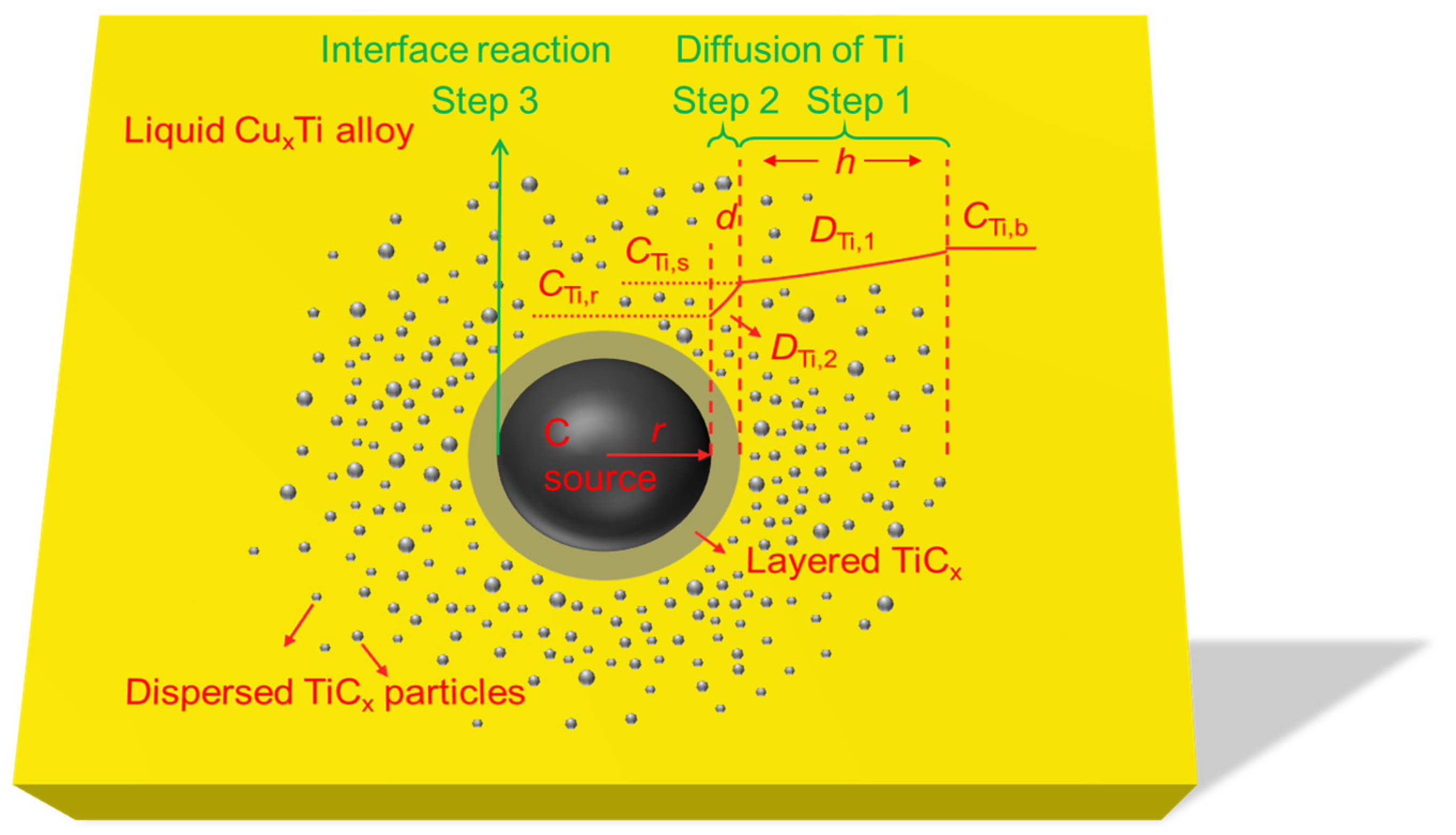
2.2. Spherical C Source

In order to simplify the reasoning process, in a previous study [27], the concentration of Ti atoms at infinity relative to the carbon source particles was taken as the original concentration of Ti in the Cu-Ti melt (CTi,b). In fact, there should be a concentration transition layer of Ti atoms near the C source. Its thickness is likely to be limited relative to the diameter of the C source particles. Therefore, the thickness of this concentration transition zone is defined as “h”, as shown in Figure 1. The in situ reaction kinetic of spherical C source particles in the Cu-Ti melt was re-derived in this paper. The specific process is described below.
For step (1) defined in Section 2.1 and shown in Figure 1,
n ˙ Ti , 1 = 4 π r 2 D Ti , 1 d C Ti d r ,
where n ˙ Ti , 1 is the diffusion flux of Ti atoms from the distant Cu-Ti melt to the layered TiCx surface (mol/s), r is the radius of the C source particles (m), DTi,1 is the diffusion coefficient of Ti atoms in the Cu-Ti melt (m2/s), and CTi is the concentration of Ti atoms (mol/m3). If this process is considered as steady-state diffusion, then the variables are separated and integrated in the above formula as follows:
n ˙ Ti , 1 r + d + h r + d d r r 2 = 4 π D Ti , 1 C Ti , b C Ti , s d C Ti
That is,
n ˙ Ti , 1 = 4 π ( r + d ) ( r + d + h ) h D Ti , 1 ( C Ti , b C Ti , s ) ,
where CTi,b and CTi,s are the concentration of Ti atoms in the Cu-Ti melt and on the layered TiCx surface, respectively (mol/m3), d is the thickness of the layered TiCx (m), and h is the concentration transition layer thickness of Ti atoms in the Cu-Ti melt (m). Equation (3) is an expression for the diffusion of Ti atoms from the Cu-Ti melt to the surface of the particles enclosed by the TiCx product layer. For step (2), the solid-state diffusion of Ti atoms through the layered TiCx is
n ˙ Ti , 2 = 4 π r 2 D Ti , 2 d C Ti d r ,
where n ˙ Ti , 2 is the diffusion flux of Ti atoms through the layered TiCx product layer (mol/s), and DTi,2 is the diffusion coefficient of Ti atoms in the layered TiCx product layer (m2/s). If the process is considered steady-state diffusion, then we have
n ˙ Ti , 2 r + d r d r r 2 = 4 π D Ti , 2 C Ti , s C Ti , r d C Ti
That is,
n ˙ Ti , 2 = 4 π r ( r + d ) D Ti , 2 ( C Ti , s C Ti , r ) d ,
where CTi,r is the Ti atom concentration on the surface of the solid C source particle (mol/m3). For step (3), in the formation reaction of TiCx at the interface between the solid C source and the layered TiCx, if this reaction is regarded as a first-order irreversible reaction, then we have
n ˙ Ti , r = 4 π r 2 k r C Ti , r ,
where n ˙ Ti , r is the reaction rate of TiCx generated at the surface of C source (mol/s), and kr is the chemical reaction rate constant. Assuming that the previous steps are in a steady state, the speed of each step is equal, i.e.,
n ˙ Ti , 1 = n ˙ Ti , 2 = n ˙ Ti , r = r Ti ,
where r Ti is the Ti atom consumption rate of the overall process (mol/s). Substituting Equation (3) into Equation (6) to remove C Ti , S and then bringing the obtained expression of C Ti , r into Equation (7), we can get
r Ti = 4 π r 2 k r C Ti , b 1 + r 2 k r h ( r + d ) ( r + d + h ) D Ti , 1 + r k r d ( r + d ) D Ti , 2 ,
assuming that r C is the consumption rate of solid C source during the reaction (mol/s). Then, we get
r Ti = 1 x r C = ρ C x × d d t ( 4 π r 3 3 ) = ρ C 4 π r 2 x × d r d t ,
where ρ C is the molar density of the solid C source (mol/m3), and x is the stoichiometry of the product TiCx. From Equations (9) and (10), we get
d r d t = x k r C Ti , b ρ C [ 1 + r 2 k r h ( r + d ) ( r + d + h ) D Ti , 1 + r k r d ( r + d ) D Ti , 2 ]
Because both D Ti , 1 and D Ti , 2 are independent of the radius r of the solid C source particle, the variables of above equation are separated and integrated as
r 0 r ρ C [ 1 + r 2 k r h ( r + d ) ( r + d + h ) D Ti , 1 + r k r d ( r + d ) D Ti , 2 ] d r = 0 t x k r C Ti , b d t ,
where r 0 is the initial radius of the solid C source particles (m), and t is the reaction time (s). The mathematical analytical solution of the reaction time t can be obtained from the above equation as follows:
ρ C { r k r h D Ti , 1 [ ln ( r + d + h ) + 2 d d 2 h ln ( r + d + h r + d ) ] k r d D Ti , 2 [ r d ln ( r + d ) ] } | r 0 r x k r C Ti , b
When r = 0, the time required for the solid C source to be completely consumed is
t total = ρ C { r 0 k r h D Ti , 1 [ ln ( r 0 + d + h ) + 2 d d 2 h ln ( r 0 + d + h r 0 + d ) ] + k r d D Ti , 2 [ r 0 - d ln ( r 0 + d ) ] } x k r C Ti , b
Through the above model, the kinetic process of the reaction of spherical solid C source particles in Cu-Ti melt under certain conditions can be evaluated, and the time for the spherical C source particles to be consumed thoroughly can be calculated.

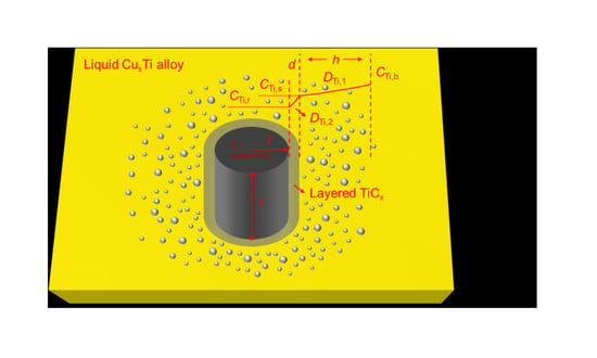
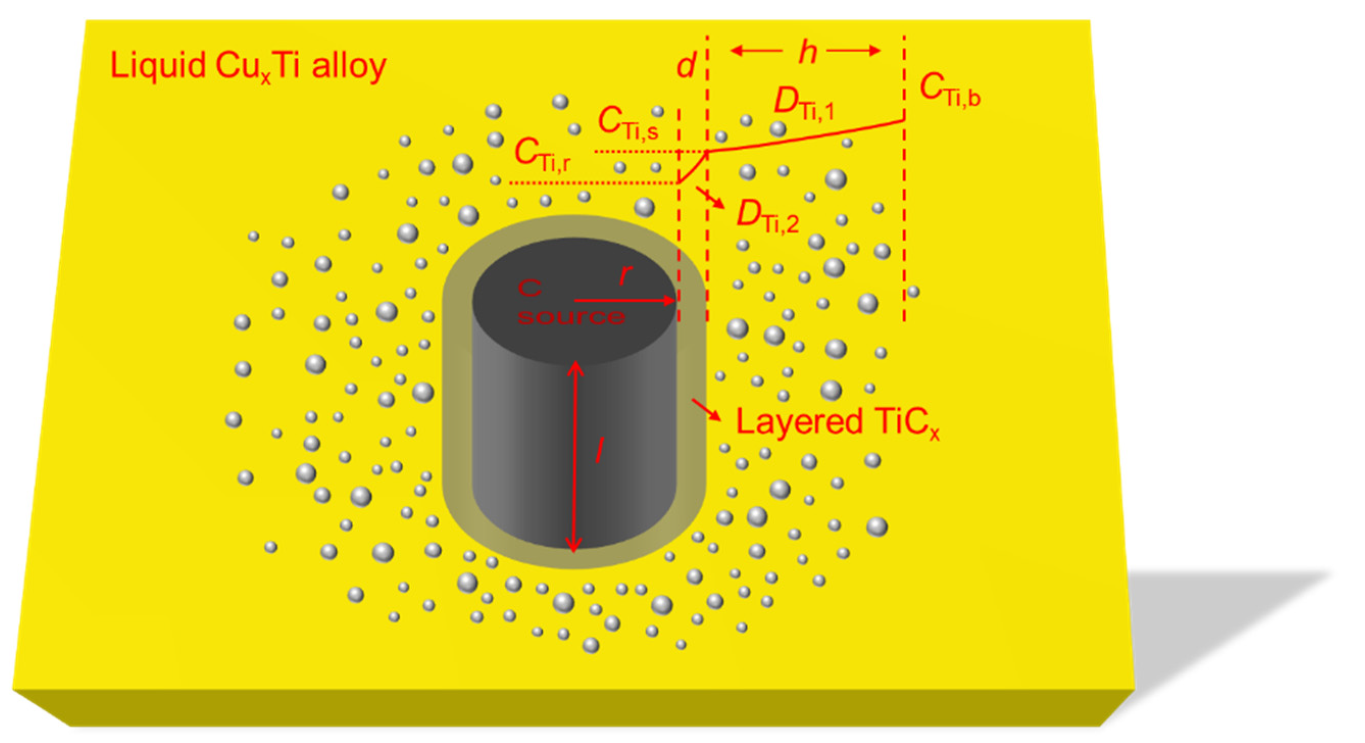
2.3. Cylindrical C Source
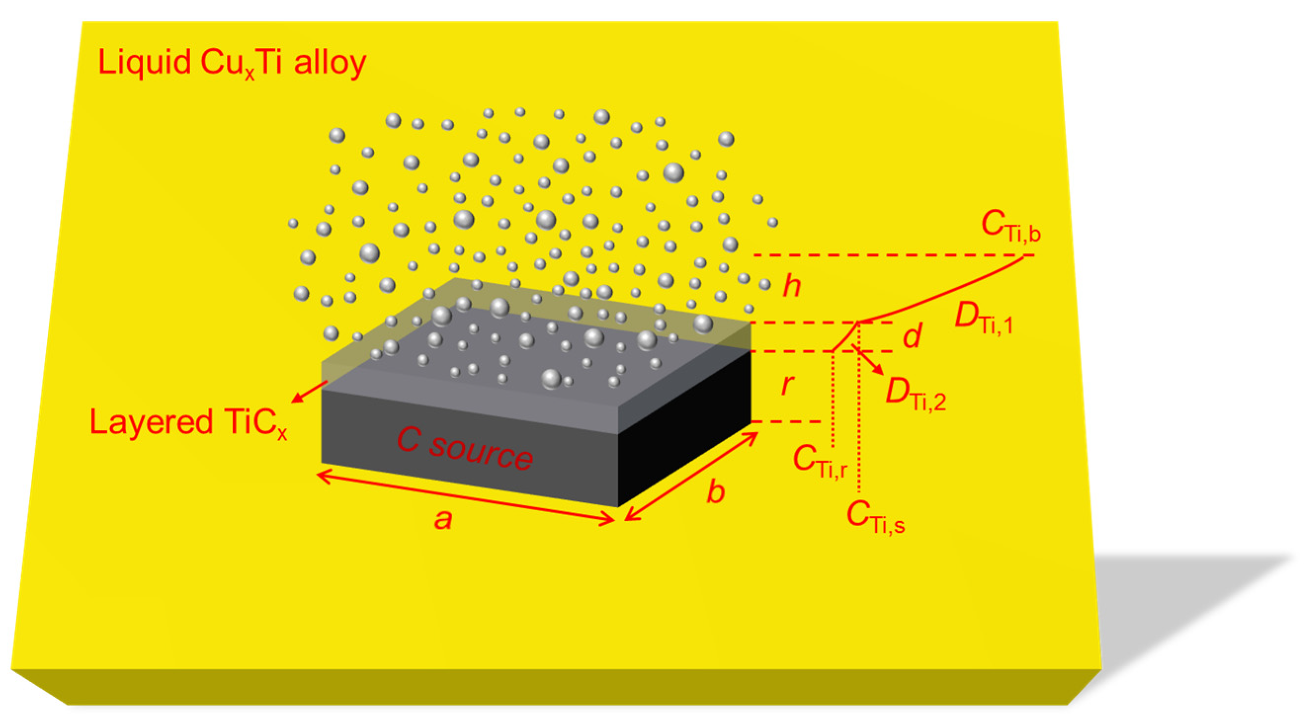
The reaction process of cylindrical solid C source particles in Cu-Ti melt is shown in Figure 2.
For step (1),
n ˙ Ti , 1 = 2 π r l D Ti , 1 d C Ti d r
When step (1) is in a steady state, we can get the equation below after separating and integrating the variables in Equation (15).
n ˙ Ti , 1 r + d + h r + d d r r = 2 π l D Ti , 1 C Ti , b C Ti , s d C Ti
That is,
n ˙ Ti , 1 [ ln ( r + d ) ln ( r + d + h ) ] = 2 π l D Ti , 1 ( C Ti , s C Ti , b ) ,
n ˙ Ti , 1 = 2 π l D Ti , 1 ( C Ti , s C Ti , b ) ln ( r + d r + d + h )
For step (2),
n ˙ Ti , 2 = 2 π r l D Ti , 2 d C Ti d r
After separating and integrating of variables in Equation (19), we get
n ˙ Ti , 2 r + d r d r r = 2 π l D Ti , 2 C Ti , s C Ti , r d C Ti ,
n ˙ Ti , 2 [ ln r ln ( r + d ) ] = 2 π l D Ti , 2 ( C Ti , r C Ti , s )
Then, we have
n ˙ Ti , 2 = 2 π l D Ti , 2 ( C Ti , r C Ti , s ) ln r r + d
Taking step (3) as a first-order irreversible reaction, ignoring the area of the upper and lower sides of the cylinder (that is, “l” is much larger than “r”), then we can get Equation (23).
n ˙ Ti , r = 2 π r l k r C Ti , r
When the in situ reaction is in a steady state, i.e., the rates of steps (1–3) are equal, then the following equation can be obtained from Equations (8), (18), (22), and (23):
r Ti = 2 π r l k r C Ti , b 1 r k r D Ti , 1 ln r + d r + d + h r k r D Ti , 2 ln r r + d
This is possible, because
r Ti = 1 x r C = ρ C x × d d t ( π r 2 l ) = 2 π ρ C r l x × d r d t
From Equations (24) and (25), we get
d r d t = x k r C Ti , b ρ C [ 1 r k r D Ti , 1 ln ( r + d r + d + h ) r k r D Ti , 2 ln ( r r + d ) ]
Upon separating and integrating variables in Equation (26), we can get
r 0 r ρ C [ 1 r k r D Ti , 1 ln ( r + d r + d + h ) r k r D Ti , 2 ln ( r r + d ) ] d r = 0 t x k r C Ti , b d t ,
from which we have
t = - ρ C { r + k r D Ti , 1 [ 1 2 [ r 2 ( d + h ) 2 ] ln ( r + d + h ) 1 4 r 2 + 1 2 r ( d + h ) ] k r D Ti , 2 ( 1 2 r 2 ln r 1 4 r 2 ) + ( k r D Ti , 2 k r D Ti , 1 ) [ 1 2 ( r 2 d 2 ) ln ( r + d ) 1 4 r 2 + 1 2 r d ] } | r 0 r x k r C Ti , b
When r = 0, the time required for complete reaction is
t total = 1 2 ρ C [ k r D Ti , 1 [ ( d + h ) 2 ln ( d + h ) ] + d 2 ln d ( k r D Ti , 2 k r D Ti , 1 ) ] x k r C Ti , b + ρ C { r 0 + k r D Ti , 1 [ 1 2 [ r 0 2 ( d + h ) 2 ] ln ( r 0 + d + h ) 1 4 r 0 2 + 1 2 r 0 ( d + h ) ] k r D Ti , 2 ( 1 2 r 0 2 ln r 0 1 4 r 0 2 ) + ( k r D Ti , 2 k r D Ti , 1 ) [ 1 2 ( r 0 2 d 2 ) ln ( r 0 + d ) 1 4 r 0 2 + 1 2 r 0 d ] } x k r C Ti , b
The model was used to describe the kinetics of the reaction of cylindrical solid C source particles in Cu-Ti melt under certain conditions, and to calculate the time for the cylindrical C source particles to achieve a complete reaction.

2.4. Flat C Source

The reaction process mechanism of flat solid C source particles in Cu-Ti melt is shown in Figure 3.
For step (1), we have
n ˙ Ti , 1 = a b D Ti , 1 d C Ti d r ,
where a and b are the length and width of the flat solid C source. When step (1) achieves steady-state diffusion, the variables in Equation (30) are separated and integrated analogously to Equation (2) or (16); afterward, we can get
n ˙ Ti , 1 = a b D Ti , 1 ( C Ti , b C Ti , s ) h
Similarly, for step (2), we have
n ˙ Ti , 2 = a b D Ti , 2 ( C Ti , s C Ti , r ) d
If the TiCx formation reaction is a first-order irreversible reaction, then
n ˙ Ti , r = a b k r C Ti , r
When the in situ reaction to generate TiCx is in a steady state, that is, the rates of steps (1–3) are equal, the following can be obtained from Equations (8), (31), (32), (33):
r Ti = a b k r C Ti , b 1 + d k r D Ti , 2 + h k r D Ti , 1
According to the stoichiometric relationship of Ti and C elements in the generated TiCx,
r Ti = 1 x r C = ρ C x × d d t ( a b r ) = ρ C a b x × d r d t
From Equations (34) and (35), we can get
d r d t = x r Ti a b ρ C = x k r C Ti , b ρ C ( 1 + d k r D Ti , 2 + h k r D Ti , 1 )
Upon separating and integrating the variables in the above equation, we have
r 0 r ρ C ( 1 + d k r D Ti , 2 + h k r D Ti , 1 ) x k r C Ti , b d r = 0 t d t
Then,
t = ( r 0 r ) ρ C ( 1 + d k r D Ti , 2 + h k r D Ti , 1 ) x k r C Ti , b
When r = 0, that is, for the total reaction time,
t total = r 0 ρ C ( 1 + d k r D Ti , 2 + h k r D Ti , 1 ) x k r C Ti , b
If r Ti , p is the rate of reaction defined by the consuming molar rate of Ti per unit time per unit surface area of the C source, then the area term in the expression of step (1) can be omitted. The relationship between r Ti , p and r Ti becomes
r Ti , p = r Ti S ,
where S for a spherical C source is 4πr2, S for a cylindrical C source is 2πrl, and S for a flat C source is ab. When the chemical reaction is the limiting link (i.e., C Ti , r C Ti , b ) in the condition of, e.g., the mechanical agitation, the diffusion resistance of Ti atoms can be ignored. At this time, for the three types of C sources,
r Ti , p = k r C Ti , r = ρ c x d r d t
After separating variables of Equation (41),
x k r ρ c C Ti , r d r = d t
For all the three types of C sources, we have
A p F p V p = 1 r 0 ,
where Ap is the original surface area of the C source, Fp is the shape factor of the C source (sphere Fp = 3, cylinder Fp = 2, flat plate Fp = 1), and Vp is the original volume of the C source [37].
Upon dividing by r0 at both sides of Equation (42), we get
x k r ρ c A p F p V p C Ti , r d r = d t r 0
For large plates, F p V p A p is half of their original thickness, and, for spheres or cylinders, F p V p A p is their original radius. Integrating Equation (44) gives
0 t x k r ρ c A p F p V p C Ti , r d r = r 0 r d t r 0
That is,
x k r ρ c A p F p V p C Ti , r t = 1 r r 0
Suppose that t * = x k r ρ c A p F p V p C Ti , r t , ξ = A p F p V p r = r r 0 , then Equation (46) can be transformed into the dimensionless form as follows:
d ξ d t * = 1
ξ = 1 and t* = 0 are the initial conditions of Equation (47), from which we can get the relationships below after integrating Equation (47).
ξ = 1 t * when   t * 1 ξ = 0 when   t * 1
The above reasoning process assumes that the C source particles all maintain their original particle shape during the reaction. The degree of reaction of the C source (X, 0 ≤ X ≤ 1) can be expressed as
X = 1 ξ F p
From Equations (48) and (49), the relationship between the degree of reaction of the C source and time can be obtained as follows:
t * = x k r ρ c A p F p V p C Ti , r t = 1 ( 1 X ) 1 F p
Thus, the time required for the C source to be completely consumed can be obtained, that is, when X = 1, we have
t X = 1 = ρ c x k r C Ti , r t F p V A pp
We then define
g F p ( X ) = 1 ( 1 X ) 1 F p
For large C source particles, the shape factor can be obtained by visual observation. For small C source particles that cannot be easily observed directly, or when their shape factor cannot be simply determined, we can set different Fp values and bring them into Equation (52). The numerical relationship between g F p ( X ) and the reaction time t can be obtained by experiment; when they show a good linear relationship with certain Fp values, then the value of Fp can be used as the shape factor of the C source. Thereafter, when the effect of Ti atom diffusion resistance is excluded in the experiment, the reaction order, activation energy, and pre-exponential factor of the reaction can be inferred through experiments under different Ti atom concentrations and different temperatures.
The above models are adjustable for different kinds of C in terms of the reaction kinetics. When it comes to some procedures like the peeling of C, the dispersion of TiCx particles, etc., further experimental investigations are needed to provide clues for the refining of this model.

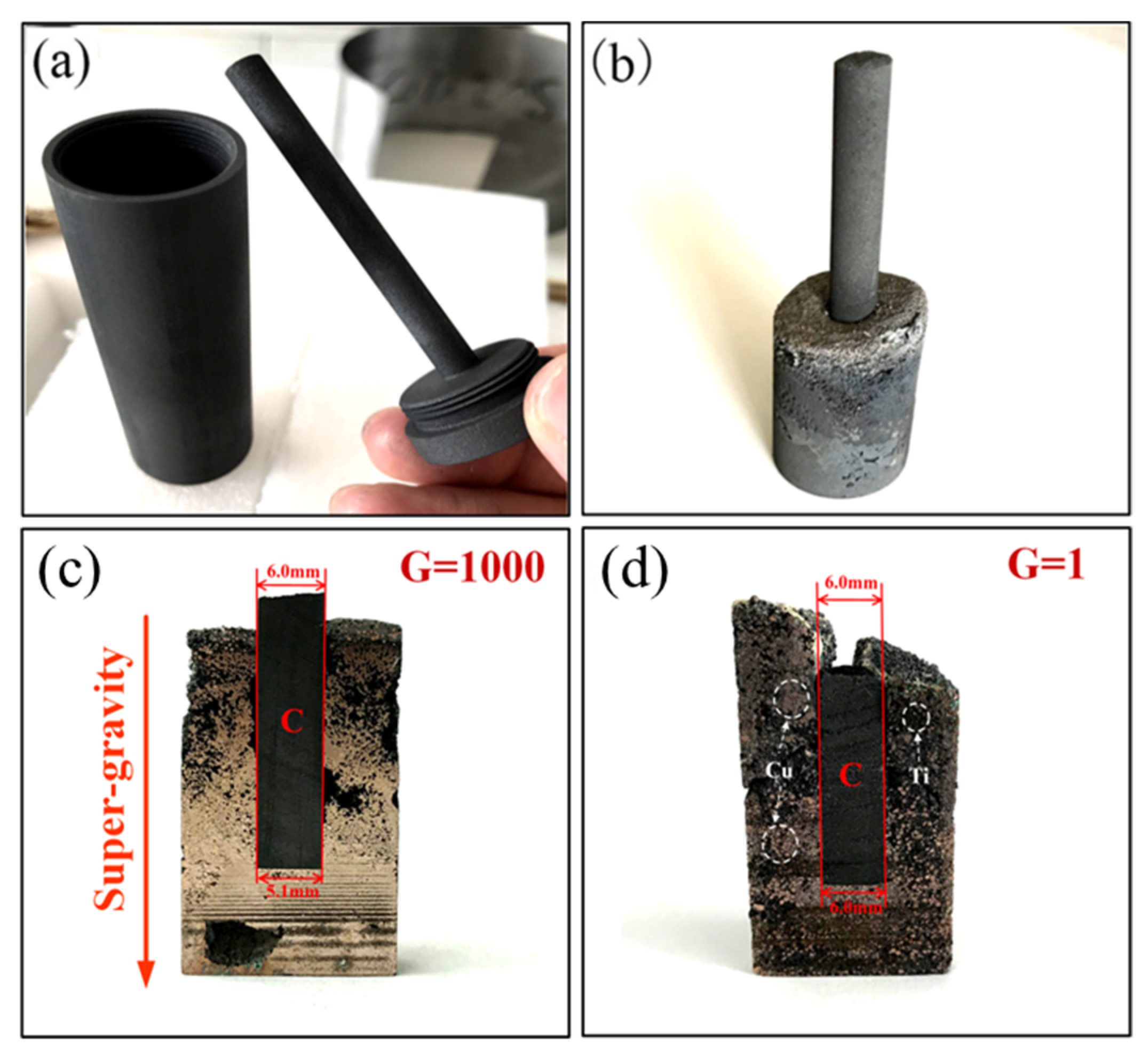
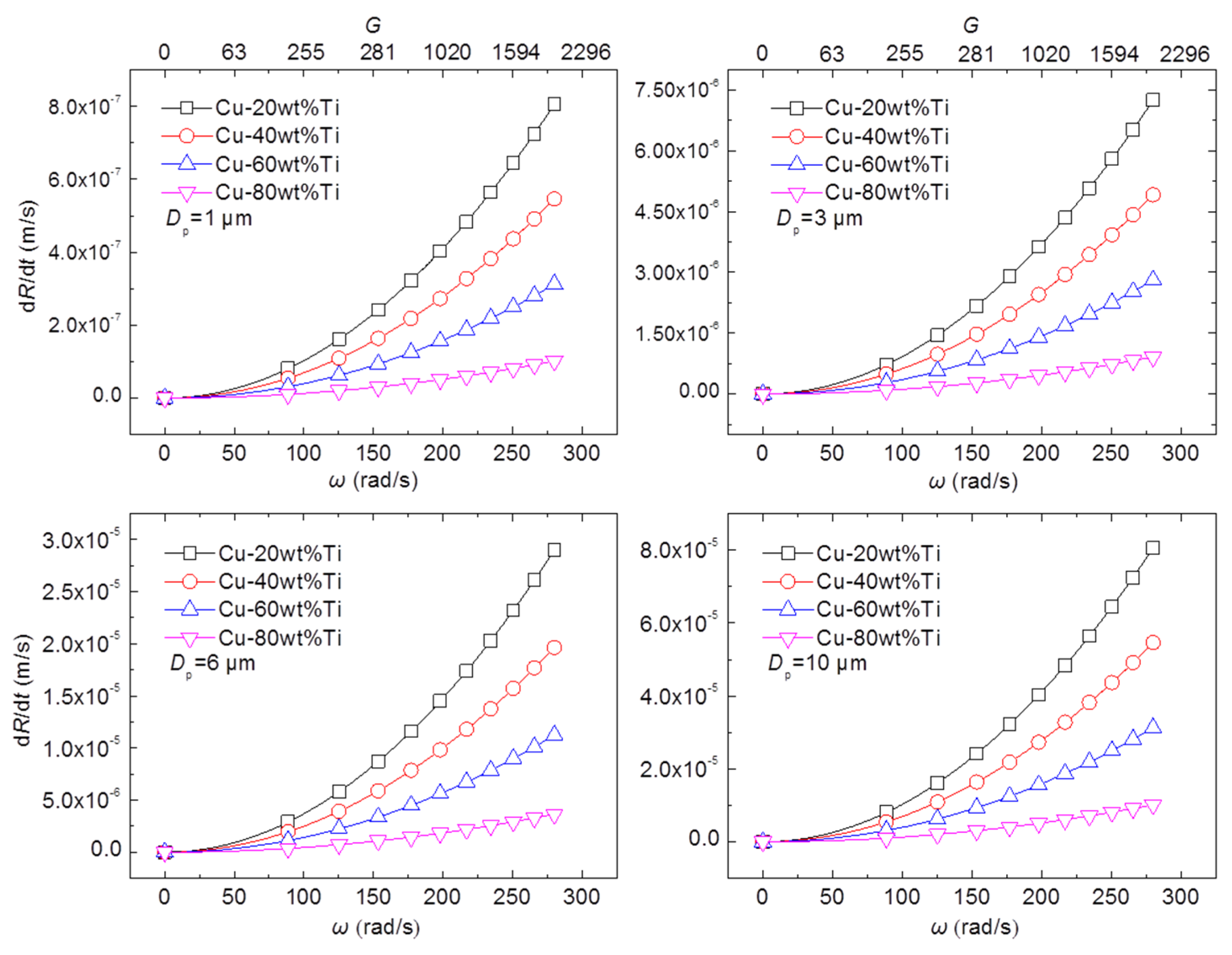
2.5. The Reaction Behavior in Super-Gravity Field

In this paper, a super-gravity field was introduced in the reaction of solid C particles in the Cu-Ti melt. The effect of the super-gravity field on the kinetics of the in situ reaction of solid C in the Cu-Ti alloy melt was experimentally verified. The sketch map of the super-gravity centrifuge used in the experiment is shown in Figure 4. In the experiment, 32 g of copper powder (25–75 μm) was mixed with 8 g of titanium powder (165–665 μm) in a graphite crucible as shown in Figure 5a, and then the graphite crucible was sealed with the graphite lid equipped with a graphite rod, before placing the set-up in the resistance furnace of the centrifugal device (Figure 4). The temperature was raised to 1250 °C at a heating rate of 10 °C/min, and the centrifuge was turned on after holding for 30 min. The centrifuge was maintained at a speed of N = 1892 rpm (gravity coefficient G = 1000 × g) for 30 min. After the test, the centrifuge and heating program were turned off, and the samples were taken out after cooling to room temperature. Comparative samples were prepared under normal gravity conditions (the remaining experimental conditions except for the gravity coefficient were the same as above). The longitudinal profile of the two samples from the center position is shown in Figure 5c,d.
The initial diameter of the C rod used in this test was 6 mm. As can be seen from Figure 5d, under normal gravity conditions, the diameter of the C rod did not change significantly, i.e., the diameters of the top and bottom of the C rod were 6 mm. Under the condition of a super-gravity field, the difference between the diameters of the top and the bottom was about 0.9 mm (Figure 5c). The main reason for this difference was that the reaction between the Cu-Ti melt and solid C was strengthened under the condition of super-gravity (G = 1000). The kinetic model for the flat C source was used as an example to analyze the reaction process under the condition of super-gravity.
If the TiCx particles and the molten Cu-Ti alloy are considered as hard spherical particles and a viscous liquid, respectively, then the moving behavior of the TiCx particles in the super-gravity field can be simulated with Stokes law [34]. There are two major forces acting on the particles: the centrifugal force and the viscous drag force, which are in opposite directions. The force balance of the particles can be expressed as follows [38,39]:
m p d 2 R d t 2 = | ρ TiCx ρ Cu - Ti | 4 3 π ( D p 2 ) 3 G g 3 π η D p d R d t ,
where R is the distance between the particles and the rotating axis of the centrifugal machine (m), dR/dt is the moving velocity (m/s), d2R/dt2 is the acceleration speed (m/s2), ρTiCx is the density of TiCx particles (4930 kg/m3), ρCu-Ti is the density of molten Cu-Ti alloy (kg/m3), Dp is the diameter of TiCx particles (m), G is the super-gravity coefficient (dimensionless), g is the gravitational acceleration (9.8 m/s2), and η is the viscosity of liquid (Pa·s). The left term in Equation (53) represents the buoyant force [39]. The first term on the right side is the centrifugal force and the second term on the right side is the viscous drag force [39]. The moving direction of the particles is determined by the relative values of densities. In this study, ρTiCx < ρCu-Ti; thus, the particles move toward the opposite direction of the centrifugal force. The terms ρTiCx, ρCu-Ti, η, and Dp in Equation (53) were assumed to be time-independent; then, Equation (53) could be solved under the initial condition of d2R/dt2 = 0 at t = 0. The solution is
d R d t = | ρ TiCx ρ Cu - Ti | G g D p 2 18 η = Δ ρ D p 2 ω 2 R 18 η ,
where ω is the rotational angular velocity (rad/s). As the moving direction of the TiCx particles is opposite to the direction of super-gravity, a negative sign is added to Equation (54). It is known that ρTiCx = 4930 kg/m3, ρCu = 8960 kg/m3, and ρTi = 4500 kg/m3. In this experiment, Dp = 3 × 10⁻⁶ m and R = 0.25 m. The rotation speed at G = 1000 was 1892 rpm (ω = 198 rad/s). Suppose that the viscosity of molten Ti is ηTi ≈ 5.2 × 10⁻³ Pa·s [40,41], and the viscosity of molten Cu is ηCu ≈ 4 × 10⁻³ Pa·s [42]. To simplify the calculation, suppose that ρCu-Ti = fCu × ρCu + fTi × ρTi and ηCu-Ti = fCu·× ηCu + fTi·× ηTi, where fCu and fTi are the mass fraction of Cu and Ti in the Cu-Ti alloy. Then, the values of △ρ (|ρTiCxρCu-Ti|) and ηCu-Ti with different Cu-Ti proportions can be obtained as listed in Table 1.
Then, according to Equation (54) and the data in Table 1, the moving velocity of TiCx particles in the Cu-Ti melt under the super-gravity field can be calculated as shown in Figure 6. It can be seen that the moving velocity of TiCx particles increases with the decrease in Ti content in the Cu-Ti melt, the increase in rotation velocity of the centrifugal apparatus, and the increase in particle diameter.
The viscosity of the melt increases with the increased number of TiCx particles in the melt, which can be expressed as follows [43]:
η = η 0 ( 1 ε ε max ) 2.5 ,
where η0 is the viscosity of the molten metal without particles (Pa·s), ε is the particle volume fraction of TiCx, and εmax is the maximum packing fraction. The volume of TiCx produced per unit time is
V TiC x = a b ρ C d r d t 48 + 12 x 12 x ρ TiC x
Assuming that the bulk density of TiCx particles precipitated around the C source at the primary stage of the in situ reaction under the constant gravity field is “ε”, then the volume of TiCx particles precipitated in the melt per unit time is
V occ = V TiC x ε
To ensure that the TiCx particles generated on the surface of the C source do not accumulate, the TiCx generated in the previous stage needs to make room for the newly generated TiCx, i.e., the TiCx particles on the surface of the C source need to float the distance of V occ a b in a unit time; then,
d R d t = V occ a b
From Equations (36), (54), and (56–58), we can get
| ρ TiCx ρ Cu - Ti | D p 2 ω 2 R 18 η = k r C Ti , b ( 4 + x ) ε ρ TiCx ( 1 + d k r D Ti , 2 + h k r D Ti , 1 )
Then,
ω = 18 η k r C Ti , b ( 4 + x ) ε ρ TiCx | ρ TiCx ρ Cu - Ti | D p 2 R ( 1 + d k r D Ti , 2 + h k r D Ti , 1 )
That is, when ω ≥ the right-hand value in Equation (60), the TiCx accumulation effect can be completely eliminated by the super-gravity field, thereby speeding up the TiCx generation reaction.

3. Conclusions

(1) For larger-size solid C sources, the kinetic models for spherical, cylindrical, and flat C-sources derived in this paper can be used to describe the reaction process. For C source particles with a small size that cannot easily distinguish the shape of the particles, a kinetic model incorporating a shape factor can be used for analysis.
(2) The introduction of a super-gravity field can promote the release of TiCx particles from the surface of C source particles, while accelerating the mass transfer. It apparently shows the speed acceleration of the in situ reaction of solid C source in Cu-Ti melt.
(3) According to the theoretical derivation, when the centrifugal velocity exceeds a certain threshold, the effect of the super-gravity field can completely avoid the accumulation of TiCx particles on the surface of the C source.

Author Contributions

L.G. established the mathematical model and wrote the manuscript. X.W. did the super-gravity experiments. Z.G. gave constructive suggestions for this work and helped design the experiments. All authors have read and agreed to the published version of the manuscript.

Funding

This research was funded by the National Natural Science Foundation of China (No.51804030) and the Key Projects of the State Key Research and Development Plan (No. 2016YFB0601304). The authors would also thank the support of the China Scholarship Council.

Conflicts of Interest

The authors declare no conflicts of interest.

Abbreviations

Ti,1Diffusion flux of Ti atoms from the distant Cu-Ti melt to the layered TiCx surface (mol/s);
rRadius of the C source particles (m);
DTi,1Diffusion coefficient of Ti atoms in the Cu-Ti melt (m2/s);
CTiConcentration of Ti atoms (mol/m3);
CTi,bConcentration of Ti atoms in the Cu-Ti melt (mol/m3);
CTi,sConcentration of Ti atoms on the layered TiCx surface (mol/m3);
dThickness of the layered TiCx (m);
hConcentration transition layer thickness of Ti atom in the Cu-Ti melt (m);
Ti,2Diffusion flux of Ti atoms through the layered TiCx product layer (mol/s);
DTi,2Diffusion coefficient of Ti atoms in the layered TiCx product layer (m2/s);
CTi,rTi atom concentration on the surface of the solid C source particle (mol/m3);
Ti,rReaction rate of TiCx generated at the surface of C source (mol/s);
krChemical reaction rate constant;
rTiTi atom consumption rate of the overall process (mol/s);
rcConsumption rate of solid C source during the reaction (mol/s);
ρ C Molar density of the solid C source (mol/m3);
xStoichiometry of the product TiCx;
r0Initial radius of the solid C source particles (m);
tReaction time (s);
a, bLength and width of the flat solid C source (m);
r Ti , p Rate of reaction defined by the consuming molar rate of Ti per unit time per unit surface area of C source (mol/(s·m2));
SSurface area of the C source particle (m2);
ApOriginal surface area of the C source;
FpShape factor of the C source;
VpOriginal volume of the C source;
RDistance between the particles and the rotating axis of the centrifugal machine (m);
ρTiCxDensity of TiCx particles (kg/m3);
ρCu-TiDensity of molten Cu-Ti alloy (kg/m3);
ρ|ρTiCxρCu-Ti |
DpDiameter of TiCx particles (m);
GSuper-gravity coefficient;
gGravitational acceleration (m/s2);
ηViscosity of liquid (Pa·s);
ηCuViscosity of molten Cu (Pa·s);
ηTiViscosity of molten Ti (Pa·s);
ηCu-TiViscosity of Cu-Ti melt (Pa·s);
ωRotational angular velocity (rad/s);
fCuMass fraction of Cu in the Cu-Ti alloy;
fTiMass fraction of Ti in the Cu-Ti alloy;
η0Viscosity of the molten metal without particles (Pa·s);
εParticle volume fraction of TiCx;
εmaxMaximum packing fraction of TiCx;
VTiCxVolume of TiCx produced per unit time;
VoccVolume of TiCx particles precipitated in the melt per unit time.

References

  1. Gotoh, Y.; Fujimura, K.; Koike, M.; Ohkoshi, Y.; Nagura, M.; Akamatsu, K.; Deki, S. Synthesis of titanium carbide from a composite of TiO2 nanoparticles/methyl cellulose by carbothermal reduction. Mater. Res. Bull. 2001, 36, 2263–2275. [Google Scholar] [CrossRef]
  2. AlMangour, B.; Grzesiak, D.; Yang, J.M. In situ formation of TiC-particle-reinforced stainless steel matrix nanocomposites during ball milling: Feedstock powder preparation for selective laser melting at various energy densities. Powder Technol. 2018, 326, 467–478. [Google Scholar] [CrossRef]
  3. Sen, W.; Xu, B.Q.; Yang, B.; Sun, H.Y.; Song, J.X.; Wan, H.L.; Dai, Y.N. Preparation of TiC powders by carbothermal reduction method in vacuum. Trans. Nonferrous Met. Soc. China 2011, 21, 185–190. [Google Scholar] [CrossRef]
  4. Lee, J.; Thadhani, N.N. Reaction synthesis mechanism in dynamically densified Ti+C powder compacts. Scripta Mater. 1997, 37, 1979–1985. [Google Scholar] [CrossRef]
  5. Boutefnouchet, H.; Curfs, C.; Triki, A.; Boutefnouchet, A.; Vrel, D. Self-propagating high-temperature synthesis mechanisms within the Ti–C–Ni system: A time resolved X-ray diffraction study. Powder Technol. 2012, 217, 443–450. [Google Scholar] [CrossRef]
  6. Contreras, L.; Turrillas, X.; Mas-Guindal, M.J.; Vaughan, G.B.M.; Kvick, Å.; Rodríguez, M.A. Synchrotron diffraction studies of TiC/FeTi cermets obtained by SHS. J. Solid State Chem. 2005, 178, 1595–1600. [Google Scholar] [CrossRef]
  7. Liang, Y.; Zhao, Q.; Zhang, Z.; Li, X.; Ren, L. Preparation and characterization of TiC particulate locally reinforced steel matrix composites from Cu–Ti–C system with various C particles. J. Asian Ceram. Soc. 2014, 2, 281–288. [Google Scholar] [CrossRef]
  8. Wei, S.F.; Feng, K.Q.; Chen, H.S.; Xiong, J.; Fan, H.Y.; Zhang, G.M.; Wang, H. Combustion synthesis of TiC/Fe–Cu composites under an electric field. J. Alloys Compd. 2012, 541, 186–191. [Google Scholar] [CrossRef]
  9. Zhang, M.X.; Hu, Q.D.; Huang, B.; Li, J.Z.; Li, J.G. Study of formation behavior of TiC in the Fe–Ti–C system during combustion synthesis. Int. J. Refract. Met. Hard Mater. 2011, 29, 356–360. [Google Scholar] [CrossRef]
  10. Thi Hoang Oanh, N.; Hoang Viet, N.; Kim, J.; Moreira Jorge Junior, A. Characterization of In-Situ Cu–TiH2–C and Cu–Ti–C Nanocomposites Produced by Mechanical Milling and Spark Plasma Sintering. Metals 2017, 7, 117. [Google Scholar] [CrossRef] [Green Version]
  11. Wang, F.; Li, Y.; Wakoh, K.; Koizumi, Y.; Chiba, A. Cu–Ti–C alloy with high strength and high electrical conductivity prepared by two-step ball-milling processes. Mater. Des. 2014, 61, 70–74. [Google Scholar] [CrossRef]
  12. Wang, F.; Li, Y.; Yamanaka, K.; Wakon, K.; Harata, K.; Chiba, A. Influence of two-step ball-milling condition on electrical and mechanical properties of TiC-dispersion-strengthened Cu alloys. Mater. Des. 2014, 64, 441–449. [Google Scholar] [CrossRef]
  13. Zhu, H.; Dong, K.; Wang, H.; Huang, J.; Li, J.; Xie, Z. Reaction mechanisms of the TiC/Fe composite fabricated by exothermic dispersion from Fe–Ti–C element system. Powder Technol. 2013, 246, 456–461. [Google Scholar] [CrossRef]
  14. Ding, H.; Chu, W.; Wang, Q.; Miao, W.; Wang, H.; Liu, Q.; Glandut, N.; Li, C. The in-situ synthesis of TiC in Cu melts based on Ti–C–Si system and its mechanism. Mater. Des. 2019, 182, 108007. [Google Scholar] [CrossRef]
  15. Rambo, C.R.; Travitzky, N.; Zimmermann, K.; Greil, P. Synthesis of TiC/Ti–Cu composites by pressureless reactive infiltration of TiCu alloy into carbon preforms fabricated by 3D-printing. Mater. Lett. 2005, 59, 1028–1031. [Google Scholar] [CrossRef]
  16. Wen, X.C.; Guo, L.; Bao, Q.P.; Gao, J.T.; Guo, Z.C. Efficient separation of lead and antimony metals from the Pb-Sb alloy by super-gravity technology. J. Alloys Compd. 2019, 806, 1012–1021. [Google Scholar] [CrossRef]
  17. Zhang, R.; He, X.; Liu, Q.; Qu, X. Improvement in Mechanical and Thermal Properties of Graphite Flake/Cu Composites by Introducing TiC Coating on Graphite Flake Surface. Metals 2019, 9, 519. [Google Scholar] [CrossRef] [Green Version]
  18. Tuan, N.Q.; Khoa, H.X.; Vieta, N.H.; Lee, Y.H.; Lee, B.H.; Kim, J.S. Fabrication of Fe-TiC Composite by High-Energy Milling and Spark-Plasma Sintering. J. Korean Powder Metall. Inst. 2013, 20, 338–344. [Google Scholar] [CrossRef] [Green Version]
  19. Rao, P.P.; Kumar, J.P.; Rahul, R. Production of Copper Metal Matrix Composite through Powder Metallurgy Route. Int. J. Eng. Technol. Sci. Res. 2017, 4, 855–864. [Google Scholar] [CrossRef]
  20. Akhtar, F.; Askari, S.J.; Shah, K.A.; Du, X.; Guo, S. Microstructure, mechanical properties, electrical conductivity and wear behavior of high volume TiC reinforced Cu-matrix composites. Mater. Charact. 2009, 60, 327–336. [Google Scholar] [CrossRef]
  21. Rathod, S.; Modi, O.P.; Prasad, B.K.; Chrysanthou, A.; Vallauri, D.; Deshmukh, V.P.; Shah, A.K. Cast in situ Cu–TiC composites: Synthesis by SHS route and characterization. Mater. Sci. Eng. A 2009, 502, 91–98. [Google Scholar] [CrossRef]
  22. Tjong, S.C.; Ma, Z.Y. Microstructural and mechanical characteristics of in situ metal matrix composites. Mater. Sci. Eng. R: Rep. 2000, 29, 49–113. [Google Scholar] [CrossRef]
  23. Westwood, A.R.C. Materials for advanced studies and devices. Metall. Trans. A 1988, 19, 749–758. [Google Scholar] [CrossRef]
  24. Mao, W.; Yamaki, T.; Miyoshi, N.; Shinozaki, N.; Ogawa, T. Wettability of Cu-Ti alloys on graphite in different placement states of copper and titanium at 1373 K (1100 °C). MMTA 2015, 46, 2262–2272. [Google Scholar] [CrossRef]
  25. Casati, R.; Vedani, M. Metal Matrix Composites Reinforced by Nano-Particles—A Review. Metals 2014, 4, 65–83. [Google Scholar] [CrossRef]
  26. Dudina, D.V.; Vidyuk, T.M.; Korchagin, M.A.; Gavrilov, A.I.; Bulina, N.V.; Esikov, M.A.; Datekyu, M.; Kato, H. Interaction of a Ti–Cu Alloy with Carbon: Synthesis of Composites and Model Experiments. Materials 2019, 12, 1482. [Google Scholar] [CrossRef] [Green Version]
  27. Guo, L.; Yang, Y.R.; Wen, X.C.; Gao, H.; Wang, Z.; Guo, Z. Synthesis of Cu-based TiCx composites via in-situ reaction between CuxTi melt and dissolvable solid carbon. Powder Technol. 2020, 362, 375–385. [Google Scholar] [CrossRef]
  28. Li, C.; Gao, J.T.; Wang, Z.; Ren, H.R.; Guo, Z.C. Separation of Fe-bearing and P-bearing phase from the steelmaking slag by super fravity. ISIJ Int. 2017, 57, 767–769. [Google Scholar] [CrossRef] [Green Version]
  29. Lu, Y.; Gao, J.T.; Wang, F.Q.; Guo, Z.C. Separation of anosovite from modified Titanium-bearing slag melt in a reducing atmosphere by supergravity. Metall. Mater. Trans. B 2017, 48, 749–753. [Google Scholar] [CrossRef]
  30. Zhang, N.; Wang, Z.; Guo, L.; Meng, L.; Guo, Z.C. Supergravity process for enriching and separating Ag from Sn–Ag–Zn melts. Chem. Eng. Process. Process Intensif. 2019, 143, 107591. [Google Scholar] [CrossRef]
  31. Meng, L.; Zhong, Y.W.; Guo, L.; Wang, Z.; Chen, K.Y.; Guo, Z.C. Recovery of Cu and Zn from waste printed circuit boards using super-gravity separation. Waste Manag. 2018, 78, 559–565. [Google Scholar] [CrossRef]
  32. Guo, L.; Wen, X.C.; Bao, Q.P.; Guo, Z.C. Removal of Tramp Elements within 7075 Alloy by Super-Gravity Aided Rheorefining Method. Metals 2018, 8, 701. [Google Scholar] [CrossRef] [Green Version]
  33. Gao, J.T.; Zhong, Y.W.; Guo, L.; Guo, Z.C. Separation of Iron Phase and P-Bearing Slag Phase from Gaseous-Reduced, High-Phosphorous Oolitic Iron Ore at 1473 K (1200 °C) by Super Gravity. Metall. Mater. Trans. B 2016, 47, 1080–1092. [Google Scholar] [CrossRef]
  34. Guo, L.; Gao, J.T.; Li, C.; Guo, Z.C. Removal of Fine SiO2/Composite Inclusions from 304 Stainless Steel Using Super-gravity. ISIJ Int. 2020. [Google Scholar] [CrossRef] [Green Version]
  35. Kivi, M.; Holappa, L.; Louhenkilpi, S.; Nakamoto, M.; Tanaka, T. Studies on Interfacial Phenomena in Titanium Carbide/Liquid Steel Systems for Development of Functionally Graded Material. Metall. Mater. Trans. B 2016, 47, 2114–2122. [Google Scholar] [CrossRef]
  36. Hayashi, T.; Matsuura, K.; Ohno, M. TiC coating on titanium by carbonization reaction using spark plasma sintering. Mater. Trans. 2013, 54, 2098–2101. [Google Scholar] [CrossRef] [Green Version]
  37. Szekely, J.; Evans, J.W.; Sohn, H.Y. Gas-Solid Reactions; Academic Press: New York, NY, USA, 1976. [Google Scholar]
  38. Watanabe, Y.; Kawamoto, A.; Matsuda, K. Particle size distributions in functionally graded materials fabricated by the centrifugal solid-particle method. Compos. Sci. Technol. 2002, 62, 881–888. [Google Scholar] [CrossRef]
  39. Watanabe, Y.; Yamanaka, N.; Fukui, Y. Control of composition gradient in a metal-ceramic functionally graded material manufactured by the centrifugal method. Compos. Part A 1998, 29, 595–601. [Google Scholar] [CrossRef]
  40. Ishikawa, T.; Paradis, P.; Okada, J.T.; Watanabe, Y. Viscosity measurements of molten refractory metals using an electrostatic levitator. Meas. Sci. Technol. 2012, 23, 25305. [Google Scholar] [CrossRef]
  41. Kaptay, G. A unified equation for the viscosity of pure liquid metals. Mater. Res. Adv. Tech. 2005, 96, 24–31. [Google Scholar] [CrossRef]
  42. Battezzati, L.; Greer, A.L. The viscosity of liquid metals and alloys. Acta Metall. 1989, 37, 1791–1802. [Google Scholar] [CrossRef]
  43. Brinkman, H.C. The Viscosity of Concentrated Suspensions and Solutions. J. Chem. Phys. 1952, 20, 571. [Google Scholar] [CrossRef]
Figure 1. The schematic diagram of the reaction mechanism of spherical solid C source particles in Cu-Ti melt.
Metals 10 00267 g001
Figure 2. The schematic diagram of reaction mechanism of cylindrical solid C source particles in Cu-Ti melt.
Metals 10 00267 g002
Figure 3. The schematic diagram of reaction mechanism of flat solid C source particles in Cu-Ti melt.
Metals 10 00267 g003
Figure 4. Sketch map of the centrifugal apparatus: 1 counterweight, 2 centrifugal axis, 3 conductive slipping, 4 thermocouple, 5 insulating layer, 6 temperature controller, 7 TiCx particles, 8 Cu-Ti melt, 9 graphite crucible.
Metals 10 00267 g004
Figure 5. Comparison of the size change in solid C rods dissolved by Cu-Ti melt under normal gravity and super-gravity conditions (a) image of the designed graphite crucible; (b) the image of the sample after heating treatment; (c) the cross-section morphology of the sample after super-gravity treatment with G = 1000; (d) the cross-section morphology of the sample after heating in normal gravity.
Metals 10 00267 g005
Figure 6. The correlation between the TiCx particle floating speed in the Cu-Ti melt and the centrifugal velocity (super gravity coefficient G).
Metals 10 00267 g006
Table 1. The values of ρCu-Ti, △ρ, and ηCu-Ti with different Cu-Ti proportions (e.g., “Cu-20 wt.% Ti” means the weight percentage of Ti in the Cu-Ti alloy is 20wt.%).
Cu-20 wt.% TiCu-40 wt.% TiCu-60 wt.% TiCu-80 wt.% Ti
ρCu-Ti (kg/m3)8068717662845392
ρ (kg/m3)313822461354462
ηCu-Ti (× 10−3 Pa·s)4.244.484.724.96

