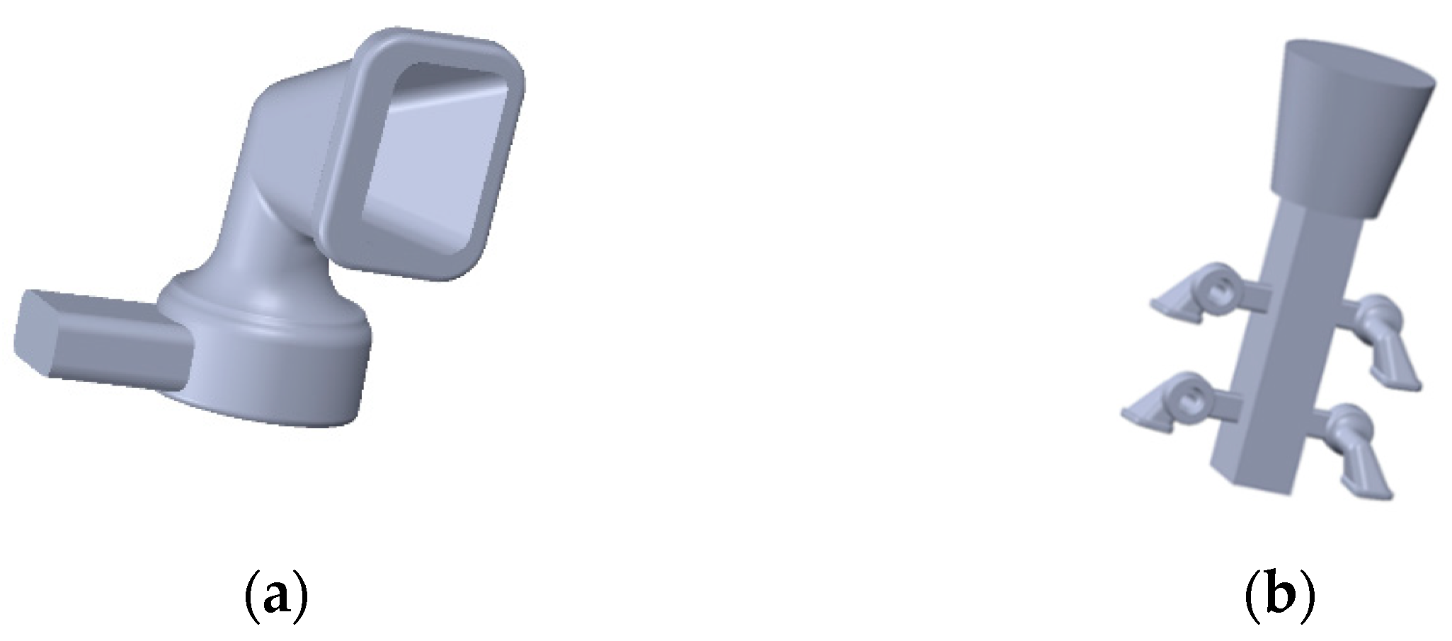
Article

Dimensional Tolerance of Casting in the Bridgman Furnace Based on 3D Printing Techniques

1
Foundry Institute, RWTH Aachen University, Intzestrasse 5, 52072 Aachen, Germany
2
State Key Laboratory for Manufacturing System Engineering, School of Mechanical Engineering, Xi’an Jiaotong University, Xi’an 710049, China
*
Author to whom correspondence should be addressed.
Metals 2020, 10(3), 299; https://doi.org/10.3390/met10030299
Submission received: 7 December 2019 / Revised: 25 December 2019 / Accepted: 4 February 2020 / Published: 25 February 2020

Abstract

:
In this article, the feasibility and the dimensional accuracy based on the 3D printing technology during investment casting of non-vacuum and Bridgman furnace are investigated based on the coordinate measuring machine to calculate the dimensional tolerances through a systematic approach. The research proved that both the investigated RC solutions are effective at obtaining cast technological prototypes in short times and at low cost, with dimensional tolerances that are completely consistent with metal casting processes.

1. Introduction

Investment casting has the advantages of high dimensional precision and high surface finish, but also has limitations, such as too many manufacturing processes and long process cycles [1,2,3]. Especially during new product development, the design drawings of the samples need to be revised repeatedly before they can be put into production, lead to a long manufacturing cycle [4,5,6,7]. In order to shorten the manufacturing cycle, considering that it is difficult to shorten the process time of shell making, our research team thinks that 3D printing technology is an effective method to replace the traditional wax mold manufacturing process [8,9]. Abroad, the research in this field has accumulated many years of experience and gradually spread to commercial applications [10,11,12,13,14]. Domestic research in this field is relatively late, but is also being actively promoted. However, the lack of theoretical foundation limits the application of this technology in enterprises, so it is necessary to obtain more experience and innovation from the level of basic research, and then to promote its application in enterprise production [15,16,17].
Based on the investment casting technology and the rapid manufacturing capability of 3D printing technology, this paper selects the melt deposition forming (FDM) technology and the light curing molding technology (SLA) through comparison and analysis [18,19,20]. The methods of manufacturing wax molds in traditional investment casting (non-directional solidification) and single crystal casting (directional solidification) have both been studied and improved [21,22,23,24,25]. The application of 3D printing technology in traditional casting was tested because of its shorter duration and lower cost, and we found the optimal 3D printing materials meeting the requirements of traditional casting (thermal cracking performance, dimensional tolerance) [26,27]. Through the final optimal material being applied to DS (single crystal casting), and then compared with several other 3D printing samples, finally, a 3D printing material suitable for both traditional casting and directional solidification was found [28,29,30].
We successfully designed and manufactured the automotive parts and the grain selector parts which can be used in production, and which provide references for the development of the new technology of wax mold production in the future [31].

2. Experimental Plan

2.1. An Automotive Machine Parts Simulation of 3D Printing Patterns

In this experiment, four parts (1) EGR (Exhaust Gas Recirculation) joint parts, (2) blocks for automotive parts, (3) intermediate plates for power tools and (4) sewing machine parts were employed for the research of the FDM molding machine printing wax mold applied to the traditional investment casting experiment.
As Figure 1 shows, a UG10.0 was used for 3D modeling first; the sprue joint design is shown in Figure 1a. Then, EGR was assembled by the design shown in Figure 1b.
In order to verify the feasibility of the casting process, ProCAST software was used to pretest the casting process of the part prior to the practical production. Simulation of the cold end inlet of the EGR valve was performed.
After the model was built, it was exported to a file in x_t format. Run the ProCAST software and select the MeshCAST module to import the x_t file for meshing for process simulation. The mesh size of the part part is set to 1 mm, and the mesh size of the gating system is set to 4 mm. Use the shelling function in MeshCAST to create a 7 mm thick case. Figure 2 shows the mesh model of the EGR joint module and its shell. The total number of nodes in the model is 168,743 and that of the grid cells is 786,499.
The grid model is generated and imported into the ProCAST module for parameter settings. The material used for the casting of EGR joints is 1.4511 stainless steel, and for the shell material is zircon sand. The contact type between the casting and the form is COINC, and the interface heat transfer coefficient is set to 750 W/(m2K). The boundary conditions and initial conditions were set. The boundary temperature was 1620 °C, the heat was selected as air-cooled, the pressure was 0.1 MPa and the filling time was 3s. The filling rate was calculated to be 0.9744 kg/s. Among the initial conditions, the casting temperature T = 1620 °C and the mold shell temperature T = 1150 °C. Finally, the operating parameters were set. Preference was for gravity filling; the maximum step length (NSTEP) was set to 300,000; and the simulation end temperature (TSTOP) was 600 °C. The porosity reduction analysis (POROS) was set to on in the thermal module and the effect of gas (GAS) was set to on in the flow module.
After completing the setting of the pre-processing parameters, the finite element solution operation was performed. The view module was selected to observe the simulation results after the calculation was completed. The filling results are shown in Figure 3.
Based on the observation of simulation results of filling process, it was found that high temperature molten metal filled down the main sprue rapidly in the initial stage. After the main sprue was filled, the lower components were filled in advance of the upper components. The filling speed was slow and stable and no obvious gas turbulence was observed. The whole filling process was completed when the feeder was full of molten metal.
The solidification process simulation results of EGR joints are shown in Figure 4.
Figure 4 and Figure 5 show the simulation results of solidification process; it can be seen that the temperature gradient distribution of the casting gradually increases from the bottom up. Therefore, it can be judged that the solidification process of the joint casting is a sequential solidification process from the bottom up, and the solidification process is reasonable, which is conducive to the feeding of the casting system to parts, and can effectively prevent the occurrence of casting defects such as shrinkage and cold separation.
Regarding the crater position of the EGR connector shown in Figure 5, the shrinkage exists only in the riser and the main channel, and the part is not loosened.

2.2. 3D Printing Pattern Producing Equipment and Procedure

According to the requirement of investment precision casting, the judgement of the wax mold material was based on melting point, thermal stability, fluidity, shrinkage rate, strength and plasticity, weldability, coating and ash content.
In the experiment of printing wax patterns in 3D printing technology, ABS plastic, PLA (polylactic acid or polylactide) plastic, and resin 8000 (resin 8000 is a printing material provided by Future Factory) were selected. The parameters of these three materials are shown in Table 1.
Resin 8000 was proven to be optimal as the wax-mold material due to its high accuracy, as shown in Table 1.
The EGR joint sample made of photosensitive resin 8000 was printed with SLA (Stereolithografie); it can be seen that the print was highly accurate and had a smooth surface (as shown in Figure 6).
Then, the manufacture of the formwork was carried out. The sand was carried out according to the standard precision casting process, and the shell was six and a half layers. The paint formulation, drying time, relative humidity and ambient wind speed were strictly controlled in the experiment. The wax in the corresponding position of the gating system was melted with a modified electric iron to form a pit full of liquid wax, connecting the gate of the part (shown in Figure 7).
Figure 8a shows the form of the second layer of the transition layer, and Figure 8b shows the case when the fourth layer is completed.
The model surface was cleaned to get rid of oil and dried for painting. The dipping process was repeated 5 times for producing a ceramic shell. The duration of drying process of 4 parts differs from the layers. The dewaxing process was carried out via steam dewaxing, first heating the shell at 170 °C for 12 min.
After removing the shells after the dewaxing in the steam kettle, it was observed that the wax in the shell had been removed, but the pattern of the resin material was not removed, and the shell was cracked due to the thermal expansion of the resin. The experimental results show that the thermal expansion coefficient of the selected bright resin material is too high to be used in direct printing of the “wax mold” experimental scheme. The cracks on the mold shell can be clearly seen from different angles in Figure 9.
The specific requirements of FDM technology for printing materials are (1) low shrinkage, (2) low melting temperature, (3) good adhesion and (4) low viscosity. Finally, ABS materials were chosen for wax model experiments considering all factors.

2.3. Casting Equipment and Procedure

ABS model parts were printed by FDM and the gating system was made of wax. This plan was low in cost and high in speed compared to printing the entire products of ABS. The 3D printing equipment was a MakeBot Replicator 2X, using FDM after selecting ABS consumables. When forming principle printed parts, the maximum molding size of the equipment was 246 mm × 152 mm × 155 mm, and the highest printing accuracy was 0.1 mm. The STL formatted file of the model was exported by UG10.0 into MakeWare. To replicate, select the support position and set the ABS parts to be printed after the parameters such as the height and print speed. At the time of printing, the temperature of the pattern material and support material was 230 °C. The layer thickness was 0.2 mm and the wall thickness was 1.2 mm when printed The four parts are shown in Figure 10.
The paint formula was adjusted to avoid breaking the shell during dewaxing and removing ABS. The dipping process was repeated 5 times until a ceramic shell was produced. The duration of the drying process of 4 parts differs from different layers. In experiments, paint formula, drying duration, wetness and blowing speed were controlled. The dewaxing process was carried out in steam dewaxing, first via heating the shell at 170 °C for 12 min. During the dewaxing process, ABS was softened rapidly and flowed out of the ceramic shell. The leftover material was removed later in the firing process. The shell was washed after firing to clean the impurities. Prior to casting, the shell was fired again. Then, the shell, just out of the oven, was filled with 200 kg of molten steel. The shell was broken when the liquid steel was cooled for 6h. The parts cut from the gating system were painted, which is shown in Figure 11.

2.4. Grain Selector Pasts

2.4.1. 3D Printing Pattern Producing Equipment and Procedure

During the experiment, one part’s patterns were made of E-glass on a EnvisionTEC Ultra 3SP machine. Machine parts’ patterns and four grain selector patterns were made of ABS on a MakerBot Replicator 2X machine. One grain selector pattern was made of EC500 on an EnvisionTEC machine. One grain selector pattern was made of photosensitive resin on a CoLiDo DLP 2.0 3D printer.

2.4.2. E-glass and EnvisionTEC Ultra 3SP Machine

The EnvisionTEC Ultra 3SP machine (Figure 12a) is one of the typical 3D printers using the DLP technique. E-Glass is one transparent material used on the 3SP series 3D printers. Featuring excellent surface finish quality and feature resolution, E-Glass 3SP is an ideal 3D printing solution for simulating clear plastics and glass for a variety of applications. The grain selector manufactured from E-Glass on EnvisionTEC Ultra 3SP is shown in Figure 12b.
E.Glass’s strength and dimensional stability offer the ability to use it for both prototypes and end use applications. The mechanical properties of E-glass are shown in Table 2.

2.4.3. ABS and MakerBot Replicator 2X Machine

The MakerBot Replicator 2X experimental 3D printer (Figure 13) is an advanced desktop 3D printer with dual extrusion that is optimal for printing with MakerBot ABS and dissolvable filaments using the FDM technique. It can create complex designs with intricate or interior supports using dis-solvable filaments.
The MakerBot Replicator 2X experimental 3D printer uses ABS filaments as raw material. ABS (shown in Figure 14a) has a high impact strength and deep colors, all with a matte finish. It has high UV resistance and can be easily post-processed. But this method is not ideal for large parts. ABS is recommended for end-use parts and environment resistance. Grain selectors made of ABS are shown in Figure 14b.
There are several advantages to this 3D printer:
  • 3D designs with two interlaced colors can print through precisely aligned dual nozzles—without swapping or pausing. ⬧ Optimal for ABS filaments.
  • It makes snaps, living hinges, threaded objects and more with a ductile, petroleum thermoplastic with elastic deformation properties.
  • It controls heating and cooling better with a super-flat heated aluminum build plate.
  • The clear, six-sided, draft-blocking enclosure helps prevent uneven cooling, shrinking and cracking.
  • It has 100 micron layer resolution.
  • Haste can be made for demonstrations and presentations with settings that range from fastdraft to finer resolution.
  • Get smooth-to-the-touch surfaces that do not need sanding, finishing or post-production ⬧ Create professional-quality, high-resolution prototypes and complex models.

2.4.4. EC500 and EnvisionTEC Machine

The Envision TEC jewelry 3D printer (as show in Figure 15a) is the 3D printer located in our institute. This machine also uses the DLP technique. EC500 is the material that we used for grain selector manufacture. A grain selector made of EC500 is shown in Figure 15b. EC500 has the competitive advantages of 30% faster build times and improved casting abilities. The EC500 material produces the highest resolution with the crispest detail without sacrificing speed and accuracy. EC500 has a melting point of 250 °C, and zero ash content on complete burn out, which makes it cast as easily as any injection wax pattern. A grain selector made of EC500 is shown in Figure 15b. Mechanical properties of EC500 are shown in Table 3.

2.4.5. Photosensitive Resin and CoLiDo DLP 2.0 3D Printer

The CoLiDo DLP 2.0 3D printer (Figure 16a) is made with a belief in quality design. It uses advanced digital light processing (DLP) 3D printing technology to create ultrafine 3D printouts. The CoLiDo DLP 3D printer’s plug and print process is just like ones using a digital projector to watch movies at home—projecting the entire slice of object and waiting for the activation of photopolymerization reaction. CoLiDo DLP 2.0 offers huge build volume, up to 50 micron layer resolution, and high speed—much greater speed than FDM. It also comes with CoLiDo fluidic natural resin. It has become affordable, easy to use and reliable. A grain selector made of photosensitive resin is shown in Figure 16b.
The major experimental difference in these studies was the material of patterns, and another difference was the wax pattern of turbine blade and grain selector printed as a whole. The parameters of all the grain selectors were measured.
Figure 17 shows grain selectors manufactured by different 3D printing methods. This experiment was carried out to analyze the dimensional accuracy of each grain selector. To simplify the experiment, cylindrical bars (SX) of MM247LC instead of turbine blades were produced.
Investment casting was applied to produce cast grain selectors. As shown in Figure 18a, grain selectors manufactured by 3D printing methods and wax bars were connected together on a tree, with wax runners and the desired gating arrangement to form a wax assembly or cluster by hot spatula.
Then, the ceramic shell was produced by dipping the combined pattern into ceramic slurries (the compositions of the front and back slurries are shown in Table 4 and Table 5), followed by stuccoing with larger particles of alumina. The ceramics reached the final thickness at the surface of the investment casting wax pattern by repeating the steps. The final green ceramic shell is shown in Figure 18b.
After that, the assemblies of the component clusters were dewaxed using a steam autoclave, and then heated to an elevated temperature in a furnace to complete pattern removal by burnout. This process prefires the green shell before it is transferred to a higher temperature furnace for final firing of the ceramic to produce a cured and strong shell.

2.4.6. Casting Procedure

This casting experiment was carried out in an industrial sized vacuum Bridgman furnace (ALD) installed at the Foundry Institute of RWTH Aachen University, shown in Figure 19. The solidification conditions in this furnace are the same as in those furnaces normally used for the commercial production of DS/SC parts. It is a two-graphite-heating-segments vacuum furnace with a tiltable induction melting crucible. This furnace can reach a vacuum degree of 5 × 10⁻⁵ mbar and the melting capacity of this furnace is 50 kg. The material used in the experiment was 4.09 kg.
The mold was placed on a chill plate and heated up in two heating zones in the Bridgman process. In order to achieve a separation between the hot and cold zone, a baffle was provided at the bottom of the heating system. For solidification, the mold was withdrawn out of the hot zone and the heat was extracted by radiation heat exchange between the mold and the black furnace chambers. The driving factor of the radiation heat exchange depends on the difference between TM4 and TF4. TM is the temperature of the mold (approximately 1500 °C) and TF is the temperature of the water-cooled furnace wall (approximately 40 °C).
Integrated in this furnace is a central control computer, through which all the process parameters as well as other control commands can be given. This control unit also enables the storage of all process information and measuring data.
A MM247LC superalloy was chosen in this research. It was one of the directional solidification materials. The liquid temperature of MM247LC was about 1368 ± 2 °C, and the solidus temperature was about 1282 ± 6 °C. The chemical composition of MM247LC is given in Table 6.
In the Bridgman furnace, the shell mold cluster was preheated, filled with superalloy melt on the chill plate (Figure 20a) and then withdrawn out of the heating zone through the baffle into the cooling zone (Figure 20b). The heating and pouring temperatures were 1460 and 1520 °C respectively. A withdrawal velocity of V = 3 mm/min was applied.
The casting mold was cooled down until the temperature in the cold zone was about 300 °C in the furnace after the casting experiment (Figure 21). The vacuum was released, and then the casting mold was taken out. Afterwards, the cast part was knocked out from the ceramic mold at the room temperature and marked. This cast part was sand blasted to remove the ceramic which stuck to the surface. Then, we got the sample, as Figure 22 shows.
Finally, dimensions of the grain selector were measured using the vernier caliper. Then, the dimensional tolerance of the material was calculated.

3. Results and Discussion

Dewaxing is the process to remove all or most of patterns, but the grain selector parts made of 3D printing material cannot melt during dewaxing process; they remain in the ceramic shell after the dewaxing process, as shown in Figure 23. Then, during the prefire process, these materials melt.
The pattern of the blade and grain selector manufactured as a whole, broke during the dewaxing process, as shown in Figure 24. Only seven castings succeeded in the experiment.
The shapes of the grain selector, the 3D printing material and the casting material are shown in Table 7.
The dimensions of the 3D printing grain selector patterns and the cast grain selectors were measured by vernier caliper. Five parameters of each grain selector were then measured. For grain selectors with column bases, the diameter of the spiral (Spiral), height of the base (height), diameter at the low position of the base (Diameter-L), diameter at the middle position of the base (Diameter-M) and diameter at the high position of the base (Diameter-H) were measured. For grain selectors with square base, diameter of the spiral (Spiral), height of the base (height), length at the low position of the base (Length-L), length at the middle position of the base (Length-M) and length at the high position of the base (Length-H) were measured. The measured parameters of 3D printed pattern and cast grain selectors are shown in Figure 25.
The results of the dimensional measurements have been used to evaluate the dimensional accuracies of the patterns and the castings. Grade of tolerance was determined by the standard of Dimensional Tolerances for Castings (lS0 8062-1984), which is shown in Table 8.

3.1. Analysis of Dimensional Accuracy of Cast Parts

In order to know the accuracy that can be achieved with the process scheme of this experiment, the dimensional accuracy and the measurement of surface roughness were measured for the four castings obtained. The parts obtained by casting were placed on a coordinate measuring machine for dimensional measurement. Measured sizes of the four parts are shown in Figure 26 and Table 9, Table 10, Table 11 and Table 12. The theoretical value here is the required size on the hair chart. The size of the print model is obtained by multiplying the hair size by 101.3%. The measured value is the size of the cast part after the printed part is cast for investment casting. The dimensional accuracy rating is obtained by querying the international general casting tolerance table.
It can be noted from these tables that the value of error is limited to a range of –0.46 to +0.24, and the grade of tolerance is CT6.

3.2. Analysis of Surface Roughness of Cast Parts

In this experiment, in the casting of four kinds of parts, each part randomly selected five pieces of each part and randomly selected two points for surface roughness measurement. The results of the measurements of the parts with the coarse super-meter are shown in Figure 27 and Table 13, Table 14, Table 15 and Table 16.
From Table 13, Table 14, Table 15 and Table 16, it can be seen that the surface roughness of the casting is in the range of 3.72 µm to 6.71 µm. Therefore, the surface roughness of the part obtained by this method can reach Ra 6.8 µm or less.

3.3. Analysis of Dimensional Accuracy of 3D Printed Patterns

The measured and calculated results of the 3D printed patterns are shown in the Table 17, Table 18, Table 19, Table 20, Table 21, Table 22 and Table 23. The measured value, standard value, error with signs and dimensional accuracy are within each table.
As shown in tables above, the dimensional accuracies of all parameters for all the patterns are between CT3 and CT6. Dimensional accuracies of pattern number 5 (Nr.5) and Nr.7 are the highest. For Nr.5 pattern, diameter of the spiral (Spiral), height of the base (height), length at the low position of the base (Length-L), length at the middle position of the base (Length -M) and length at the high position of the base (Length -H) are CT3. For Nr.7 pattern, dimensional accuracies of the diameter of the spiral (Spiral), height of the base (height), diameter at the low position of the base (Diameter-L), diameter at the middle position of the base (Diameter-M) and diameter at the high position of the base (Diameter-H) are CT3. Nr.5 and Nr.7 were both made of ABS material on the MakerBot Replicator 2X machine. The dimensional accuracy of pattern Nr.6, which is made of E-glass, is the lowest.

3.4. Analysis of Dimensional Accuracies of Cast Grain Selectors

The measured and calculated results of the cast grain selectors are shown in the Table 24, Table 25, Table 26, Table 27, Table 28, Table 29 and Table 30. The measured value, standard value, error with signs and dimensional accuracy are within each table.
As shown in tables above, the dimensional accuracy of all parameters for all the castings is between CT3 and CT7. The dimensional accuracy of casting Nr.4 is lowest; the dimensional accuracy of diameter of the spiral (Spiral) is CT7; the dimensional accuracy of height of the base (height) is CT7. A possible reason is that photosensitive resin material expands more seriously than other materials. The dimensional accuracy of the base part for Nr.6 casting is lower than those of other castings, because of the variation of the Nr.6 pattern made of E-glass.

3.5. Comparison of 3D Printed Patterns and Castings

As shown in Figure 28, for ABS patterns, the variation of Spiral is 0.07–0.31, the variation of height is 0.14–0.29 and the variation of base is 0–0.06. For photosensitive resin pattern, the variation of Spiral is 0.35, the variation of height is 0.35 and the variation of base is 0.03–0.1. For E-glass pattern, the variation of Spiral is 0.05, the variation of height is 0.22 and the variation of base is 0.15–0.39. For castings made from ABS patterns, the variation of Spiral is 0.15–0.28, the variation of height is 0.26–0.54 and the variation of base is 0.05–0.38. For castings made from photosensitive resin patterns, the variation of Spiral is 0.5, the variation of height is 0.81 and the variation of base is 0.04–0.17. For castings made from E-glass patterns, the variation of Spiral is 0.18, the variation of height is 0.21 and the variation of base is 0.3–0.37.
We can see from the figures that the variations of castings correspond to the variations of 3D printed patterns. Regarding these five parameters together, ABS material shows the best dimensional accuracy.

4. Summary and Outlook

The dimensional accuracy of the wax pattern introduces a great influence on the final product’s dimensions, and thus, on the finishing process. Dimensional changes between the pattern producing process and its corresponding cast part occur as a result of thermal expansion, shrinkage, hot deformation and creep of the pattern material, mold material and solidifying alloy during the processing. It is of great importance to investigate the dimensional tolerance of the patterns manufactured by 3D printing techniques and the corresponding cast part.
The experiment was divided into two parts, traditional investment casting and directional solidification.
In the traditional investment casting experiment, the application of FMD technology in investment casting was conducted. Four types of parts were selected for experiments. The specific process was as follows: Firstly, UG10.0 was used to design and optimize the three-dimensional model of the part, and a combined model including the part and the casting system was designed. The combined model was imported into ProCAST to make numerical simulation to ensure the feasibility of the casting process.
In the selection of material for printing wax patterns, three materials, ABS, PLA and resin, were tested and compared. Resin was chosen due to its high dimensional accuracy, but the mold shells cracked after dewaxing, because resin has poor thermal expansion ability. A comparison of ABS and PLA materials has shown that better experimental results of mold shell and dewaxing process were obtained by ABS.
Then, the part model was imported into MakeWare, the print parameters and process support were set, the parts were printed and the ABS print was obtained. The ABS prints manufactured by 3D printing were used instead of the traditional wax molds in investment casting, and the operations of shell casting, dewaxing, roasting, pouring, smashing, cutting, grinding gates and sand blasting were performed in the investment casting process. After measuring and analyzing the dimensional precision and surface accuracy of each of the four parts, the dimensional accuracy of this experiment was shown to reach CT5, and the surface roughness could reach Ra 6.8 µm.
In this experiment, the ProCAST process plan for parts was simulated in advance, which effectively avoided casting defects such as shrinkage porosity and cold septa, and reduced product development costs. The use of FMD technology to manufacture ABS parts for investment casting eliminated the need for an open wax mold and shortened the time of new product development. Through experiments on four types of parts, the process was found to be versatile for new product development and low-volume production. This experimental program has very good prospects for industrial application.
During the directional solidification experiment, one grain selector pattern was made of E-glass on an EnvisionTEC Ultra 3SP machine. Four grain selector patterns were made of ABS on the MakerBot Replicator 2X machine. One grain selector pattern was made of EC500 on the EnvisionTEC machine. One grain selector pattern was made of photosensitive resin on the CoLiDo DLP 2.0 3D printer. Through this research, grain selector patterns made of ABS material on the MakerBot Replicator 2X 3D printer showed the highest dimensional accuracy. Due to the 3D printing times and costs, and the dimensional accuracies of different methods, ABS material is the best material, and will be used for further research.
Patterns manufactured by 3D printing techniques have their advantages. 3D printing techniques allow the simultaneous development and validation of the product and of the manufacturing process. Traditionally, in order to produce cast prototypes, a model and eventual cores have to be created; the process for manufacturing is a very time-consuming process and is also expensive for low volume production. Therefore, when the number of castings required is small in quantity, it is not economical in terms of both cost and time to produce the metal tools using traditional methods. Hence, it is necessary to reduce the time investment and costs of single crystal investment casting via intermediate approaches, such as 3D printing techniques. Furthermore, grain selectors manufactured by 3D printing techniques can support smaller spiral diameters.
Grain selectors manufactured by 3D printing techniques show critical problems. These patterns cannot melt during the dewaxing process; they remain in the ceramic shell after dewaxing. The mold shell shows some cracks in the grain selector part. Besides, the grain selector and blade manufactured by EC500 on the EnvisionTEC machine failed as a whole. The shell mold broke during dewaxing, which means the solid blade pattern made of EC500 is not suitable for investment casting.
In the next step, patterns using in investment casting manufactured by 3D printing techniques can be made hollow. During the dewaxing process, the pattern can expand inwards, in order to not generate cracks on the shell mold. Hollow patterns can also save material and weight.
Another improvement that can be made on the 3D printed pattern is the “overall pattern.” First, the blade and grain selector can be manufactured as a whole. Then, the overall wax tree can be manufactured as a whole. There are several benefits of the “overall pattern”:
It decreases the artificial defects during the wax binding process and saves time.
When doing the simulation, the “overall pattern” manufactured by 3D printing technique and the CAD file were exactly the same. Simulation results can be more accurate.
More complicated design of the casting system can be applied.

Author Contributions

Conceptualization, X.Z.; methodology, X.Z.; software, X.Z.; validation, X.Z.; formal analysis, X.Z.; investigation, X.Z.; resources, X.Z.; data curation, X.Z.; writing-original draft preparation, X.Z.; writing-review & editing, X.Z.; visualization, X.Z.; supervision, F.W., D.M. and A.B.-P. All authors have read and agreed to the published version of the manuscript.

Funding

This research was supported by German Research Foundation through Grant No. BU1072/44-1.

Acknowledgments

All the colleagues of GI and Access as well as, especially Lembrecht, Dietmar; Schaberger-Zimmermann, Elke; Frieß, Jessica; Pustal, Björn who have assisted in this work and given me useful advises are carefully acknowledged.

Conflicts of Interest

The authors declare no conflict of interest.

References

  1. Cheah, C.M.; Chua, C.K.; Lee, C.W. Rapid prototyping and tooling techniques: A review of applications for rapid investment casting. Int. J. Adv. Manuf. Technol. 2005, 25, 308–320. [Google Scholar] [CrossRef]
  2. Pham, D.T.; Gault, R.S. A comparison of rapid prototyping technologies. Int. J. Mach. Tools Manuf. 1998, 38, 1257–1287. [Google Scholar] [CrossRef]
  3. Greul, M.; Pintat, T.; Greulich, M. Rapid prototyping of functional metallic parts. Comput. Ind. 1995, 28, 23–28. [Google Scholar] [CrossRef]
  4. Beeley, P.R.; Smart, R.F. Investment Casting, 1st ed.; The Institute of Materials: London, UK, 1995. [Google Scholar]
  5. Jones, S.; Marquis, P.M. Role of silica binders in investment casting. Br. Ceram. Trans. 1995, 94, 68–73. [Google Scholar]
  6. Reed, R.C. The Superalloys: Fundamentals and Applications; Cambridge University Press: Cambridge, UK, 2006. [Google Scholar]
  7. Aubertin, P.; Cockcroft, S.; Fernihough, J. Metallurgical aspects of casting of singlecrystal airfoils for use in aero-engines and industrial gas turbines. In Proceedings of the 10th World Conference on Investment Casting, Monte Carlo, India, 14–17 May 2000. [Google Scholar]
  8. Mitchell, A. New casting directions for gas turbine construction. In Proceedings of the 24th BICTA Conference on Investment Casting, Oxford, UK, 6–8 June 1999. [Google Scholar]
  9. Tsunekane, M.; Suzuki, A.; Pollock, T.M. Single-crystal solidification of new Co–Al–Wbase alloys. Intermetallics 2011, 19, 636–643. [Google Scholar] [CrossRef]
  10. Wagner, A.; Shollock, B.A.; McLean, M. Grain structure development in directional solidification of nickel-base superalloys. Mater. Sci. Eng. A 2004, 374, 270–279. [Google Scholar] [CrossRef]
  11. Konter, M.; Thumann, M. Materials and manufacturing of advanced industrial gas turbine components. J. Mater. Process. Technol. 2001, 117, 386–390. [Google Scholar] [CrossRef]
  12. Hugo, F.; Betz, U.; Ren, J.; Huang, S.-C.; Bondarenko, J.A.; Gerasimov, V. International Symposiumon on Liquid Metal. Processing and Casting; Mitchell, A., Ridgway, L., Baldwin, M., Eds.; AVS: New York, NY, USA, 1999; pp. 16–30. [Google Scholar]
  13. Elliott, A.J.; Pollock, T.M.; Tin, S.; King, W.T.; Huang, S.C.; Gigliotti, M.F.X. Directional solidification of large superalloy castings with radiation and liquid-metal cooling: A comparative assessment. Metall. Mater. Trans. A 2004, 35, 3221–3231. [Google Scholar] [CrossRef]
  14. Elliott, A.J.; Pollock, T.M. Thermal analysis of the bridgman and liquid-metal-cooled directional solidification investment casting processes. Metall. Mater. Trans. A 2007, 38, 871–882. [Google Scholar] [CrossRef]
  15. Konter, M.; Kats, E.; Hofmann, N. Superalloys; Pollock, T.M., Kissinger, R.D., Bowman, R.R., Green, K.A., McLean, M., Olson, S.L., Schirra, J.J., Eds.; TMS: Warrendale, PA, USA, 2000; pp. 189–200. [Google Scholar]
  16. Bewlay, B.P.; Lipsitt, H.A.; Jackson, M.R.; Reeder, W.J.; Sutliff, J.A. Solidification processing of high temperature intermetallic eutectic-based alloys. Mater. Sci. Eng. A 1995, 192, 534–543. [Google Scholar] [CrossRef]
  17. Gheisari, H.; Karamian, E. Characterization and investigation of grain selection in spiral grain selectors during casting single-crystal turbine blades. J. Mod. Process. Manuf. Prod. 2015, 4, 19–28. [Google Scholar]
  18. Lefebvre, A.H. Gas. Turbine Combustion; CRC Press: Boca Raton, FL, USA, 1998. [Google Scholar]
  19. Caron, P.; Khan, T. Evolution of Ni-based superalloys for single crystal gas turbine blade applications. Aerosp. Sci. Technol. 1999, 3, 513–523. [Google Scholar] [CrossRef]
  20. Yang, X.L.; Dong, H.B.; Wang, W.; Lee, P.D. Microscale simulation of stray grain formation in investment cast turbine blades. Mater. Sci. Eng. A 2004, 386, 129–139. [Google Scholar] [CrossRef]
  21. Royce, R. The Jet Engine, 4th ed.; Technical Publications Department: Derby, UK, 1992; ISBN 0-902-121-04-9. [Google Scholar]
  22. De Bussac, A.; Gandin, C.A. Prediction of a process window for the investment casting of dendritic single crystals. Mater. Sci. Eng. A 1997, 237, 35–42. [Google Scholar] [CrossRef]
  23. Siredey, N.; Denis, S.; Lacaze, J. Dendritic growth and crystalline quality of nickel-base single grains. J. Cryst. Growth 1993, 130, 132–146. [Google Scholar] [CrossRef]
  24. Carter, P.; Cox, D.C.; Gandin, C.A.; Reed, R.C. Process modelling of grain selection during the solidification of single crystal superalloy castings. Mater. Sci. Eng. A 2000, 280, 233–246. [Google Scholar] [CrossRef]
  25. Aveson, J.W.; Tennant, P.A.; Foss, B.J.; Shollock, B.A.; Stone, H.J.; D’Souza, N. On the origin of sliver defects in single crystal investment castings. Acta Mater. 2013, 61, 5162–5171. [Google Scholar] [CrossRef]
  26. Giamei, A.F.; Anton, D.L. Rhenium additions to a Nibase superalloy: Effects on microstructure. Metall. Trans. A 1985, 16, 1997–2005. [Google Scholar] [CrossRef]
  27. Caron, P.; Khan, T. Development of a new nickel based single crystal turbine blade alloy for very high temperatures. Adv. Mater. Process. 1990, 1, 333–338. [Google Scholar]
  28. Pessah, M.; Caron, P.; Khan, T. Effect of phase on the mechanical properties of a nickelbase single crystal superalloy. Miner. Met. Mater. Soc. 1992, Superalloys 1992, 567–576. [Google Scholar]
  29. Walston, W.S.; O’Hara, K.S.; Ross, E.W.; Pollock, T.M.; Murphy, W.H. René N6: Third generation single crystal superalloy. Miner. Met. Mater. Soc. 1996, Superalloys 1996, 27–34. [Google Scholar]
  30. Zheng, Y.R.; Wang, X.P.; Dong, J.X.; Han, Y.F. Effect of Ru addition on cast nickel base superalloys with low content of Cr and high content of W.Pennsylvania. In Proceedings of the 9th International Symposium on Superalloys, Champion, PA, USA, 17–21 September 2000. [Google Scholar]
  31. Aune, R.; Battezzati, L.; Brooks, R. Thermophysical properties of IN738LC, MM247LC and CMSX-4 in the liquid and high temperature solid phase. Superalloys 2005, 718, 625–706. [Google Scholar]
Figure 1. (a) 3D model of EGR (exhaust gas recirculation) joint with gate, (b) 3D model of EGR joint module.
Metals 10 00299 g001
Figure 2. EGR joint module and its shell model.
Metals 10 00299 g002
Figure 3. Simulation results of filling process of EGR joint.
Metals 10 00299 g003
Figure 4. Simulation results of solidification process of the EGR joint.
Metals 10 00299 g004
Figure 5. Simulation results of shrinkage cavity position of the EGR joint.
Metals 10 00299 g005
Figure 6. SLA printing EGR joint sample of photosensitive resin.
Metals 10 00299 g006
Figure 7. Module of the EGR joint.
Metals 10 00299 g007
Figure 8. (a) Two layered and (b) four layered shells of the EGR joint.
Metals 10 00299 g008
Figure 9. Cracked mold shell seen from different angles (a) and (b)
Metals 10 00299 g009
Figure 10. Four printed parts. (a) EGR connector printout; (b) pad prints; (c) nail in the plate print; (d) sewing machine accessory prints.
Metals 10 00299 g010
Figure 11. Castings of four parts. (a) EGR joint casting; (b) casting of pad blocks; (c) nail in the plate casting; (d) sewing machine parts casting.
Metals 10 00299 g011aMetals 10 00299 g011b
Figure 12. (a) The EnvisionTEC Ultra 3SP machine and (b) a grain selector made from E-glass.
Metals 10 00299 g012
Figure 13. The MakerBot Replicator 2X experimental 3D printer.
Metals 10 00299 g013
Figure 14. (a) White ABS material. (b) Grain selectors made of ABS.
Metals 10 00299 g014
Figure 15. (a) MakerBot Replicator 2X experimental 3D printer and (b) a grain selector made of EC500.
Metals 10 00299 g015
Figure 16. (a) CoLiDo DLP 2.0 3D printer and (b) a grain selector made of photosensitive resin.
Metals 10 00299 g016
Figure 17. Grain selectors manufactured by different 3D printing methods.
Metals 10 00299 g017
Figure 18. (a) The assembled wax pattern with the spiral grain selector, and (b) the final green ceramic shell after stuccoing.
Metals 10 00299 g018
Figure 19. ALD vacuum Bridgman furnace installed at the Foundry Institute.
Metals 10 00299 g019
Figure 20. (a) Bridgman process during pouring superalloy; (b) Bridgman process during withdrawing.
Metals 10 00299 g020
Figure 21. Casting mold in the Bridgman furnace after casting.
Metals 10 00299 g021
Figure 22. Grain selectors cast from MM247LC.
Metals 10 00299 g022
Figure 23. Remaining grain selectors manufactured with 3D printing material after the dewaxing process.
Metals 10 00299 g023
Figure 24. Failed ceramic shell mold for EC500 material.
Metals 10 00299 g024
Figure 25. Measured parameters of 3D printed pattern and cast grain selectors.
Metals 10 00299 g025
Figure 26. Dimensional measurement schematic.
Metals 10 00299 g026
Figure 27. Dimensional measurement schematic (roughness range from 3.72 μm to 6.71 μm).
Metals 10 00299 g027
Figure 28. Dimensional measurement schematic.
Metals 10 00299 g028
Table 1. Properties of resin 8000, ABS plastic and PLA plastic.
IndexResin8000ABSPLA
Print accuracy/mm0.020.10.1
Glass transition temperature/°C7010560
Melting temperature/°C165–195150–180165–185
Fluiditybadnormalnormal
Shrinkage ratesmall5%small
Weldabilitybadnormalnormal
Coating performancegoodnormalNormal
Table 2. Mechanical properties of E-glass.
ParametersValue at 30 s × 2 Post Curing TimeValue at 5 min × 2 Post Curing Time
Tensile Strength48 MPa21 MPa
Tensile Modulus1950 MPa2000 MPa
Elongation at Break3%1.15%
Flexural Strength79 MPa75 MPa
Table 3. Mechanical properties of EC500.
Tensile Strength57 MPa
Elongation at Break3.6%
Flexural Strength129 MPa
Flexural Modulus3155 MPa
Heat deflection temperature130 °C at 0.455 MPa, 78 °C at 1.82 MPa
Specific gravity1.10–1.11g\cm3
Viscosity760cp at 25 °C
Table 4. Composition of the front slurry.
ContentsTrademarkPercentage of Mass25 Kg Mixture
Distilled water-5.50%1.37 kg
BinderLudox Px-3017.82%4.45 kg
Benetzervictawet 120.30%0.075 kg
DefoamerBrust1000.03%0.007 kg
CondenserDolapixCE640.25%0.062 kg
CondenserDolapixA880.10%0.025 kg
Solid fuelMatroxid MR7020%5 kg
Solid fuelNabalox NO1136%1.5 kg
Solid fuelAlodur WSK30-70um50%12.5 kg
Table 5. Composition of the back slurry.
ContentsTrademarkPercentage of Mass20 kg Mixture25 kg Mixture
BinderLudox Px-3024.73%4.94 kg6.18 kg
Benetzervictawet 120.25%0.05 kg0.062 kg
DefoamerBrust1000.02%0.004 kg0.005 kg
Solid fuelMatroxid MR7045%9.0 kg11.25 kg
Solid fuelAlodur WSK30-70um30%6.0 kg7.5 kg
Table 6. Chemical composition of MM247LC (wt %).
CCrCoMoWTaTiAlBZrHfNi
0.07890.5103.20.75.60.0150.011.4Bal
Table 7. Overview of the cast grain selector and the corresponding 3D printed pattern.
NumberShape of Grain SelectorPattern MaterialCasting Material
12D-C-column baseABSMM247LC
22D-C-square baseABSMM247LC
33D-column baseABSMM247LC
43D-column basePhotosensitive ResinMM247LC
52D-Z-square baseABSMM247LC
62D-Z-column baseE glassMM247LC
72D-Z-column baseABSMM247LC
83D-column baseEC500failed
Table 8. Dimensional tolerances for castings (lS0 8062-1984).
Basic Size of CastingGrade of Tolerance
fromtoCT3CT4CT5CT6CT7
30.140.200.280.400.56
360.160.240.320.480.64
6100.180.260.360.520.74
10160.200.280.380.540.78
16250.220.300.420.580.82
25400.240.320.460.640.90
Table 9. EGR joint casting size measurement results.
No.Standard Value/mmMeasured Value/mmError/mmGrade of Tolerance
120.1019.96−0.14CT6
227.5027.55+0.05CT6
3φ13.60φ13.36−0.24CT6
4φ23.80φ23.34−0.46CT6
Table 10. Dimension measurements of the block castings.
No.Standard Value/mmMeasured Value/mmError/mmGrade of Tolerance
17.007.11+0.11CT6
2φ8.20φ8.13−0.07CT6
3R14.75R14.89+0.24CT6
423.0022.88−0.12CT6
Table 11. Nail in the plate casting size measurement results.
No.Standard Value/mmMeasured Value/mmError/mmGrade of Tolerance
195.4095.09−0.31CT6
225.5025.24−0.26CT6
332.8532.96+0.11CT6
φ6.05φ6.09+0.04CT6
Table 12. Sewing machine accessories’ casting size measurement results.
No.Standard Value/mmMeasured Value/mmError/mmGrade of Tolerance
15.505.58+0.08CT6
214.1014.27+0.17CT6
310.109.94−0.06CT6
4φ8.50φ8.36−0.14CT6
Table 13. EGR joint casting surface roughness measurement results.
No.12345
Measured value/µm4.985.125.005.164.71
No.678910
Measured value/µm5.265.085.435.145.09
Table 14. Test results of surface roughness of spacer castings.
No.12345
Measured value/µm4.884.635.164.614.39
No.678910
Measured value/µm4.554.395.233.724.98
Table 15. Nail in the plate surface roughness measurement results.
No.12345
Measured value/µm4.294.815.565.536.71
No.678910
Measured value/µm5.396.255.485.994.62
Table 16. Sewing machine parts’ surface roughness measurement results.
No.12345
Measured value/µm4.035.114.884.954.92
No.678910
Measured value/µm5.326.065.254.624.03
Table 17. Dimensional measurements of number 1 (Nr.1) 3D printed pattern (ABS).
PatternParameterMeasured ValueStandard ValueError with SignsDimensional Accuracy
Nr.1Spiral3.1730.17CT4
Height30.29300.29CT4
Diameter-L15.01150.01CT3
Diameter-M14.9715−0.03CT3
Diameter-H15150CT3
Table 18. Dimensional measurements of Nr.2 3D printed pattern (ABS).
PatternParameterMeasured ValueStandard ValueError with SignsDimensional Accuracy
Nr.2Spiral3.1530.15CT 4
Height30.22300.22CT 3
Length-L13.03130.03CT 3
Length-M13.03130.03CT 3
Length-H13.04130.04CT 3
Table 19. Dimensional measurements of Nr.3 3D printed pattern (ABS).
PatternParameterMeasured ValueStandard ValueError with SignsDimensional Accuracy
Nr.3Spiral3.3130.31CT 6
Height30.27300.27CT 4
Diameter-L15.02150.02CT 3
Diameter-M14.9615−0.04CT 3
Diameter-H15150CT 3
Table 20. Dimensional measurements of Nr.4 3D printed pattern (photosensitive resin).
PatternParameterMeasured ValueStandard ValueError with SignsDimensional Accuracy
Nr.4Spiral3.3530.35CT 6
Height30.35300.35CT 5
Diameter-L15.09150.09CT 3
Diameter-M15.1150.1CT 3
Diameter-H15.03150.03CT 3
Table 21. Dimensional measurements of Nr.5 3D printed pattern (ABS).
PatternParameterMeasured ValueStandard ValueError with SignsDimensional Accuracy
Nr.5Spiral3.0730.07CT 3
Height30.14300.14CT 3
Length-L12.9513−0.05CT 3
Length-M12.9413−0.06CT 3
Length-H12.9513−0.05CT 3
Table 22. Dimensional measurements of Nr.6 3D printed pattern (E-glass).
PatternParameterMeasured ValueStandard ValueError with SignsDimensional Accuracy
Nr.6Spiral3.0530.05CT 3
Height29.7830−0.22CT 3
Diameter-L14.6115−0.39CT 6
Diameter-M14.7415−0.26CT 4
Diameter-H14.8515−0.15CT 3
Table 23. Dimensional measurements of Nr.7 3D printed pattern (ABS).
PatternParameterMeasured ValueStandard ValueError with SignsDimensional Accuracy
Nr.7Spiral3.1230.12CT 3
Height30.16300.16CT 3
Diameter-L14.9915−0.01CT 3
Diameter-M14.9615−0.04CT 3
Diameter-H15.02150.02CT 3
Table 24. Dimensional measurements of Nr.1 cast grain selector.
CastingParameterMeasured ValueStandard ValueError with SignsDimensional Accuracy
Nr.1Spiral3.2430.24CT 5
Height30.54300.54CT 6
Diameter-L14.8515−0.15CT 3
Diameter-M14.6215−0.38CT 5
Diameter-H14.6315−0.37CT 5
Table 25. Dimensional measurements of Nr.2 cast grain selector.
CastingParameterMeasured ValueStandard ValueError with SignsDimensional Accuracy
Nr.2Spiral3.1530.15CT 4
Height30.26300.26CT 4
Length-L12.8313−0.17CT 3
Length-M12.813−0.2CT 3
Length-H12.7813−0.22CT 4
Table 26. Dimensional measurements of Nr.3 cast grain selector.
CastingParameterMeasured ValueStandard ValueError with SignsDimensional Accuracy
Nr.3Spiral3.2830.28CT 5
Height30.27300.27CT 4
Diameter-L14.9215−0.08CT 3
Diameter-M14.7615−0.24CT 4
Diameter-H14.815−0.2CT 3
Table 27. Dimensional measurements of Nr.4 cast grain selector.
CastingParameterMeasured ValueStandard ValueError with SignsDimensional Accuracy
Nr.4Spiral3.530.5CT 7
Height30.81300.81CT 7
Diameter-L14.915−0.1CT 3
Diameter-M14.8315−0.17CT 3
Diameter-H14.9615−0.04CT 3
Table 28. Dimensional measurements of Nr.5 cast grain selector.
CastingParameterMeasured ValueStandard ValueError with SignsDimensional Accuracy
Nr.5Spiral3.1730.17CT 4
Height30.41300.41CT 5
Length-L12.9513−0.05CT 3
Length-M12.7913−0.21CT 4
Length-H12.9413−0.06CT 3
Table 29. Dimensional measurements of Nr.6 cast grain selector.
CastingParameterMeasured ValueStandard ValueError with SignsDimensional Accuracy
Nr.6Spiral3.1830.18CT 4
Height30.21300.21CT 3
Diameter-L14.6315−0.37CT 5
Diameter-M14.715−0.3CT 5
Diameter-H14.6515−0.35CT 5
Table 30. Dimensional measurements of Nr.7 cast grain selector.
CastingParameterMeasured ValueStandard ValueError with SignsDimensional Accuracy
Nr.7Spiral3.230.2CT 4
Height30.38300.38CT 5
Diameter-L14.7615−0.24CT 4
Diameter-M14.7115−0.29CT 5
Diameter-H14.8115−0.19CT 3

