Article

Effects of Microstructure Evolution on Fretting Wear Behaviors of 25CrNi2MoVE Steel under Different Tempering States

1
School of Mechanical and Automotive Engineering, South China University of Technology, Guangzhou 510640, China
2
National Engineering Research Center of Near-Net-Shape Forming for Metallic Materials, Guangzhou 510640, China
3
School of Mechanical Engineering and Automation, Qishan Campus, Fuzhou University, Fuzhou 350108, China
4
Inner Mongolia First Machinery Group Co., Ltd., Baotou 014032, China
*
Authors to whom correspondence should be addressed.
Metals 2020, 10(3), 351; https://doi.org/10.3390/met10030351
Submission received: 15 February 2020 / Revised: 4 March 2020 / Accepted: 5 March 2020 / Published: 8 March 2020

Abstract

:
Increasing load requirements and harsh operating conditions have worsened the wear of drive shafts in special field vehicles. In this paper, the evolution of the microstructure and fretting wear behaviors of 25CrNi2MoVE torsion shaft steel and their influence on the wear mechanisms were investigated as a function of tempering temperature. The results showed that the coarse grain size, low matrix hardness and non-metallic inclusions in the as-received state lead to a high wear rate and serious adhesive wear. The grain refinement after normalizing and the formed M5C2 carbide and bainite helped to improve the wear resistance and worn surface quality. Low temperature tempering is conducive to further improve the wear resistance of normalized samples, and the wear rate and worn surface roughness are increased gradually after tempering temperature increases. For quenching, although martensite structure can achieve a lower wear rate, the coefficient of friction is much higher; the wear mechanisms are primarily fatigue wear and adhesive wear. Although the adhesive wear degree and worn surface roughness were increased, the optimal anti-wear performances are obtained under tempering at 350 °C with good continuity of the surface oxide film. Excessive tempering temperature will make the softened matrix unable to form a beneficial “third-body wear”.

1. Introduction

Fretting wear mostly occurs when two contact bodies undergo oscillating shear traction and small relative slip amplitude [1]. This type of damage is inevitable and will eventually lead to the durability of the components being reduced greatly [2]. Torsion shaft is the key component of large special vehicle suspension systems and can reduce the impact of the vehicle body during operation. Therefore, in most cases, the torsion shaft is often subjected to complex conditions of torsion, bending, impact and tensile and is prone to fracture failure. In general, torsion fatigue and fretting wear are mutually reinforcing, and fretting wear under torsion is faster than under ordinary bending load [3]. In the case of large torsion angle or torque, the contact surface between the fretting components will produce large relative displacement, which also means more serious fretting wear. Wang et al. [4] pointed out that the micro-cracks caused by fretting wear can rapidly nucleate and expand to aggravate fatigue failure of metal materials. In the shafting, there are many places where fretting wear may occur, such as shaft necks, splines and threads [5,6]. However, damage to the torsion shaft caused by fretting wear has not been paid enough attention for a long time.
In general, the factors affecting fretting wear can be summarized as contact conditions (e.g., point/surface contact), environmental conditions (e.g., force or frequency) and material properties (e.g., chemical compositions and heat treatment). Among them, improper heat treatment has become one of the main factors of fatigue failure and wear failure of automobile components [7]. Tempering treatment is usually considered as the last step of heat treatment of mechanical components. The microstructure of the matrix and the type of carbide precipitates will be stabilized after tempering. Moreover, the microstructure changes of workpiece during operation due to high temperature, long exposure time and local overheating can easily lead to secondary tempering [8]. Therefore, the influence of tempering conditions on the final wear resistance of components has always been a concern.
The direct influence of different heat treatment conditions on metal materials is the difference of material microstructure. Over the past few decades, many studies have reported the relationship between microstructure and wear resistance of metallic materials. It is widely accepted that carbide precipitate size and porosity during heat treatment have a big effect on wear [9,10]. Grain boundary structure and steel composition are also considered to play an important role in wear behaviors. For example, some studies suggest that the wear may proceeded by grain boundary fatigue [11]. Kesavan et al. [12] mentioned the importance of type and quantity of precipitates in wear properties of nickel base hard-faced coating. Similarly, large amounts of alloying elements in alloy steels promote the precipitation of certain types of carbides (such as M2C and M5C2), which shows a positive effect on improving wear resistance [13,14]. Hussainova et al. [15] also believed that compared with hardness, the microstructure is more applicable to explain wear resistance of material. However, most of the studies on the influence of tempering conditions on the wear properties of steel are limited to the evaluation of wear loss, while only a few studies focus on the wear mechanism. Sahin et al. [16] reported that the sliding wear mechanism of ferritic ductile iron with dual matrix does not change significantly with increasing tempering time. Wei et al. [17] conducted a dry sliding wear test on H13 steel treated at different tempering temperatures and found that tempering at relatively low temperatures helps to improve the anti-adhesive wear resistance, but the resistance to oxidation wear is weak. Coronado et al. [18] studied the effect of tempering temperature on the abrasive wear resistance of mottled cast iron in two-body and three-body contact systems, and they evaluated the correlation between the wear rate and the residual austenite volume fraction, volume and matrix hardness. Fretting wear is a typical type of synergic and complex wear form, which usually includes four wear mechanisms (i.e., adhesive wear, abrasive wear, fatigue wear and corrosion/oxidative wear) at the same time [19]. Each of the wear mechanisms contributes different degrees to fretting wear under different tempering states. This makes the discussion of the fretting wear mechanism of metal materials under different tempering conditions more meaningful.
Although many advanced materials have long been considered to have excellent resistance to wear and corrosion, high costs have limited their large-scale application. Presently, researchers have developed a series of high strength steels with excellent wear resistance, low production cost and competitive performance for the torsion shaft, such as 45CrNiMoVA [20], TORKA-ESR [21] and 30CrMnSiA [22], and many of them have been successfully applied. 25CrNi2MoVE steel is also a novel high strength special shaft steel developed for field service vehicles. In this paper, 25CrNi2MoVE steel was taken as the target material. The effect of tempering temperature (200~850 °C) on fretting wear behavior of a special torsion shaft was investigated and a fretting test was carried out using an oscillating reciprocating friction and wear tester. The correlations of wear behaviors and microstructure, grain properties and carbide precipitates of 25CrNi2MoVE steel under different tempering states were systematically studied and discussed. On this basis, the typical fretting wear mechanisms of 25CrNi2MoVE steel are also discussed.

2. Experimental Details

2.1. Material and Heat Treatment

The chemical compositions of 25CrNi2MoVE steel in the as-received state are provided by the professional steel manufacturer (Sichuan Liuhe Forging Co., Ltd., Jiangyou, China) according to the batch of raw materials, as shown in Table 1. The raw materials were produced using an electric furnace-ladle refining-vacuum degassing process, and the steel bars with diameter of 80 mm were obtained by spheroidizing annealing, continuous rolling and finish turning. Block samples with a size of 10 mm × 8 mm × 10 mm were cut out from the outermost side of the steel bar for microstructure analysis and the fretting wear test after heat treatment.
JmatPro software has been widely used in metal solidification simulation [23]. In order to establish a reasonable heat treatment process, the present work analyzed the subcooled austenite continuous cooling transition (CCT) curve of 25CrNi2MoVE steel. After simulation calculation, the transition temperatures of various phases of 25CrNi2MoVE steel were obtained as follows: Ac1 = 659.2 °C, Ac3 = 743.9 °C, Ms = 357.8 °C and Mf = 243.2 °C (as shown in Figure 1).
Eldis [24] also proposed an empirical equation for the prediction of phase transition temperature Ac1 and Ac3 based on the mass fraction of alloying elements in steel, which is applicable to alloy steel with carbon content less than 0.6 w.%:
Ac 1 = 712 17.8 Mn 19.1 Ni + 20.1 Si + 11.9 Cr + 9.8 Mo
Ac 3 = 871 254.4 C 14.2 Ni + 51.7 Si
where each element symbol represents the corresponding element mass fraction w.% in the steel. According to Table 1, Equation (1) and (2), the empirical values of Ac1 and Ac3 of 25CrNi2MoVE steel can be calculated to be 686.7 °C and 724.9 °C respectively, which are very close to the critical value of phase transition simulated by JmatPro software. Meanwhile, it can also be obtained that the phase-transition temperatures of ferrite, bainite and pearlite during the cooling process of austenitization are 743.9 °C, 525.9 °C and 659.2 °C respectively. According to the CCT curve, all samples were austenitized at 850 °C for 30 min and produced in a chamber-type electric resistance furnace. In addition to the as-received (AR) state samples, another 10 groups of different treatment processes were produced to evaluate the response of the steel to fretting wear, as summarized in Table 2.

2.2. Material Characterization

The hardness of the sample under all material states was measured with a Vickers microhardness tester (HDV-10002, SCTMC, Shanghai, China); the tester force was set as 1.961 N (200 gf) and the dwelling time was 15 s. The samples were polished and etched with 4% Nital solution to reveal the metallographic structure features. The fretting wear surface morphology and metallographic structure were investigated using optical microscope (OM; Leica M165C, Solms, Germany) and a scanning electron microscope (SEM; Quanta 200 & Nova nanosem 430, FEI, Hillsboro, OR, USA). An energy dispersive spectrometer (EDS) with an accelerating voltage of 20 kV was utilized to qualitative elementary analysis of the surfaces of the AR state material, both the unworn and worn areas of specimens. X-ray diffraction analysis was carried out on the sample’s surface under the excitation radiation of Cu-Kα radiation (λ = 1.54056 Å) using an X-ray diffractometer (XRD; D8 Advance, Bruker-axs, Karlsruhe, Germany), and the phase structure of each typical anti-wear sample was obtained respectively. JMatPro software (Version 9.0, Sente Software, Guildford, UK) was used to simulate and calculate a 25CrNi2MoVE steel phase diagram and composition, providing support for analysis of metallographic structure and phase.

2.3. Fretting Wear Test and Calculation of Volumetric Wear Rate

The typical fretting wear test with ball-on-flat contact configuration was carried out using an oscillating friction and wear tester (SRV IV, Optimol, Munchen, Germany); the principle of the test rig is illustrated in Figure 2.
In the test, 25CrNi2MoVE steel was processed into a block sample with dimensions of 8 mm × 10 mm × 14 mm and with an original surface roughness Ra of about 0.32 μm. The GCr15 steel ball with a diameter of 10 mm, surface roughness Ra of 0.025 μm and hardness of 728 HV0.2 was selected as the upper tribo-pair material. The test was carried out at room temperature (about 25 °C) in the air. The humidity of the air was constant at about 40~45%, and the lubrication condition was set as dry friction. In order to ensure the stability and reliability of the test results, 5 N was preloaded before the test to achieve the purpose of running-in, and the loading duration was 5 min. Meanwhile, at least three fretting wear tests were carried out in each material state, and the test results were used to calculate the steady coefficient of friction (CoF). The detailed parameters of fretting wear tests are shown in Table 3.
Before and after the fretting wear test, the sample was cleaned and dried in 50% petroleum ether alcohol solution. A universal 3D profilemeter (UP series, Retc-instruments, USA) was used to measure the profile of wear scar, and the length (x), width (y) and depth (z) were obtained with the accompanying Gwyddion software (Version 2.44, Czech metrology institute, Brno, Czech Republic). The approximate volumetric wear loss of the lower sample, V, can be calculated based on the following equation [25]:
V = π h 2 ( 3 ρ h ) / 3
where h is the maximum depth of the fretting wear scar of the lower sample, and the approximate curvature radius (ρ) of the wear scar concave surface can be expressed as:
ρ = ( l · d + 4 h 2 ) / 8 h
where l is the maximum length of the wear scar along the fretting direction, and d is the maximum width of the wear scar perpendicular to the fretting direction. Further, the volumetric wear rate, Kv, can be calculated with the equation mentioned by Bonny et al. [26]:
K v = V / F N s
where FN is the imposed normal contact force, and s is relative slip distance (each cycle defined as twice the stroke of the arm, 400 μm). The depth, length and width of the wear scar measured at least three times were used to evaluate the Kv value.

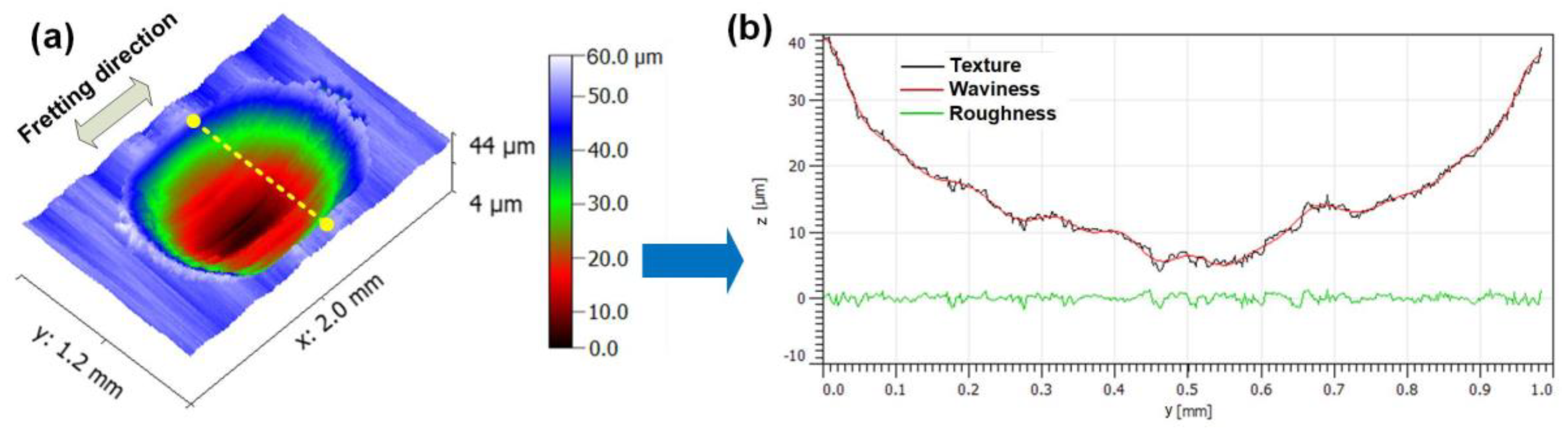
2.4. Measurements of Worn Surface Roughness (WSR)

The WSR Rz (average maximum height of the profile) was measured using Gwyddion software mentioned in Section 2.3. To ensure the consistency of the results, the WSR of all samples was measured at least three times near the center of wear scar, and the measurement scanning direction was perpendicular to the fretting sliding direction. An example of measured WSR on 25CrNi2MoVE steel is presented in Figure 3.

3. Results and Analysis

3.1. Fretting Wear Behaviors

3.1.1. Coefficient of Friction

Figure 4 presents the CoF curves of 25CrNi2MoVE steel under different material states after testing. Except for the initial 5 min of running-in stage, all curves are satisfied with the three-body contact theory for fretting wear. That is, the asperity of the tribo-pair surface first contacts and keeps a low CoF for a short time; the subsequent adhesion of the surface material causes the gradual rise of the CoF. When the debris formed due to the spalling of surface asperity, the two-body contact turned into three-body contact. At this point, the adhesive wear is inhibited and the CoF gradually decreases. Finally, the CoF reaches a steady state after the dynamic balance of continuous formation and discharge of the debris. Obviously, in the AR state, the material surface reached the steady wear stage earlier, with the CoF at a relatively low level (CoF = 0.691), and it increased after heat treatment (Figure 4a). By averaging the CoFs after each curve enters the steady wear stage, steady CoF in different material states can be obtained (Figure 4d). With the variation of tempering temperature, a difference showed between the surface CoF of normalized and quenched samples. The CoF on the surface of the normalized sample decreased significantly only at low tempering temperature (CoF = 0.632), but it was basically greater than or close to AR state at other tempering temperatures. The CoF of the quenched sample basically maintained a decreasing trend and then rose again when the tempering temperature reached 550 °C. The CoF of the quenched sample after tempering at 350 °C is the smallest, which is 0.641. Additionally, the hardness after quenching will obviously be higher than that of the AR state, but it can be observed that the CoF for the NQ850 sample is higher at the steady stage. Therefore, hardness is not a precise criterion to predict the CoF.

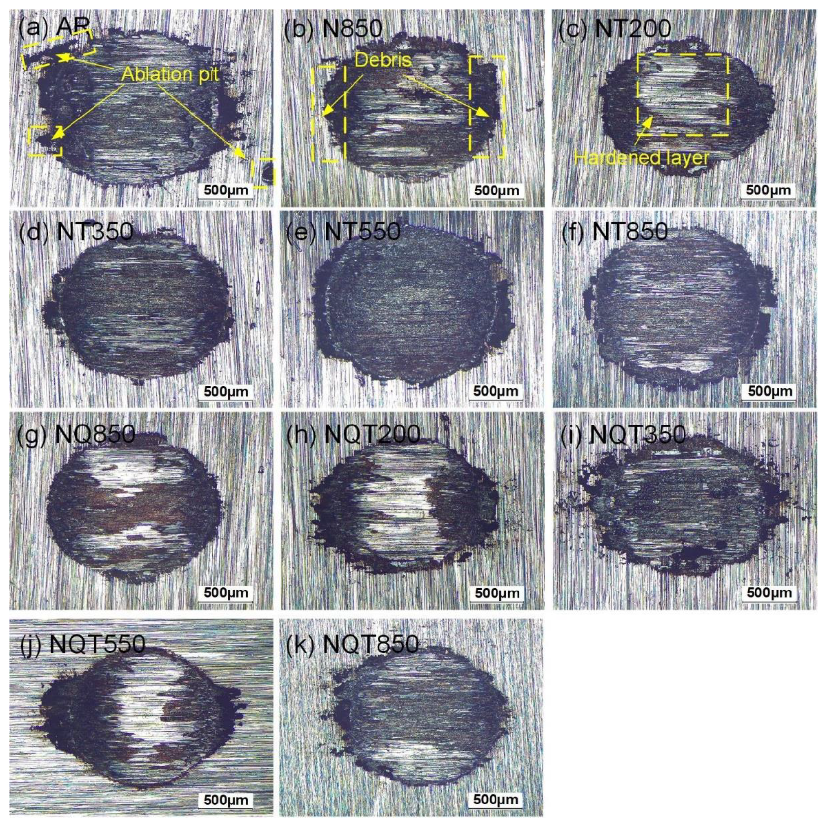
3.1.2. Worn Morphologies and Volumetric Wear Rate (Kv)

Figure 5 shows the optical morphologies of the worn surface of different material states. It can be seen from the figure that an approximate elliptic wear scar was formed on the surface of the samples after the fretting wear test. A lot of black oxide accumulation and small ablation pits could be observed at the edge of the wear scar, which indicated that there was severe surface wear in the process of fretting and that material fell off during the relative movement of the contact pair. Under the action of reciprocating motion, the surface temperature rises and a molten pool is formed. The interaction of temperature and shear force causes the droplets in the molten pool to splash out of the ablation area and form the surface ablation pits. Some of the splashed molten droplets reach the surface of the metal matrix, and the regular ablation point is formed after solidification and cooling. It is found that there is no direct correlation between ablation pits and wear resistance of materials, and some badly worn surfaces also have neat grinding edges and fewer ablation pits. In addition, white bright layers can be observed on the worn surface of some samples to different degrees. These white bright layers are more obvious on the surface of the sample with higher matrix hardness, indicating that this should be the cold hardening layer produced by extrusion during wear.
The 3D morphologies of worn surface under different tempering states are given in Figure 6. It can be seen from these figures that the cross-sectional profiles of the worn surfaces present an ellipse under the normal pressure of a GCr15 ball, and the edges of two sides shows a convex platform due to extrusion and accumulation of wear debris. Generally, the samples with excellent fretting wear resistance will present a shallower or narrower wear scar.
Combined with Figure 6 and Equation (3)–(5), the Kv value of each tempering sample after the fretting wear test can be obtained, as shown in Figure 7. The Kv value in AR state was the highest, reaching 5.274 × 10⁻² mm3/Nm.
For the normalized sample, the Kv value was significantly reduced by 36% compared with AR state, reaching 3.374 × 10⁻² mm3/Nm. After tempering at 200 °C, the Kv value further decreased to 2.646 × 10⁻² mm3/Nm. However, after tempering at 350 °C, 550 °C and 850 °C, the Kv value of the material began to rebound and increase, which was 4.382 × 10⁻², 5.139 × 10⁻² and 4.357 × 10⁻² mm3/Nm, respectively.
For the quenched sample, the Kv value decreased by 30.2% compared with AR state, reaching 3.683 × 10⁻² mm3/Nm. After tempering at 200 °C and 350 °C, the Kv value of the quenched samples decreased to 2.809 × 10⁻² and 2.251 × 10⁻² mm3/Nm, respectively. At 550 °C and 850 °C, the Kv value increased to 3.182 × 10⁻² and 2.789 × 10⁻² mm3/Nm, respectively.

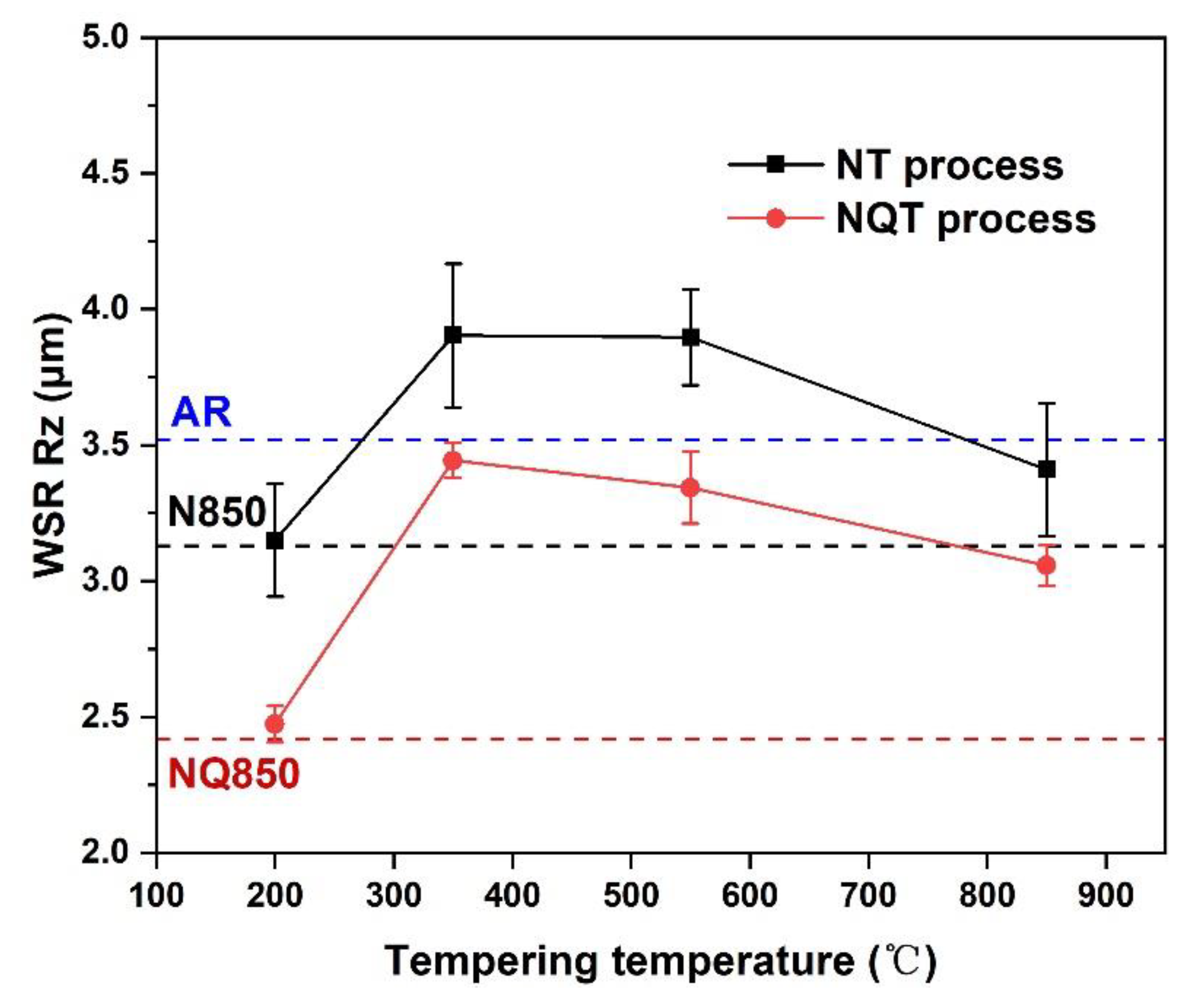
3.1.3. Worn Surface Roughness Rz

Surface roughness is an important evaluation index for mechanical wear [27]. Figure 8 shows the variation of WSR Rz values under different tempering states. It can be seen that the WSR in AR state reached 3.53 μm after the wear test. Normalizing and quenching showed positive effects on reducing WSR, which decreased by 11.2% and 31.5% respectively. After tempering at 200 °C, the WSR of all samples began to increase again. When the tempering temperature was increased to 350 °C, the WSR of the samples under both processes returned to the highest level. After the tempering temperature reached 550 °C, the WSR began to decline slowly. At 850 °C, the WSR of the sample showed a further downward trend.

3.2. Relationship between Microhardness and Wear Properties

Figure 9 shows the variation of microhardness of 25CrNi2MoVE steel under different material states. As can be seen from the figure, with the increase of tempering temperature, the hardness of each sample will decrease, but all of them are higher than that of AR state (277.8 HV0.2). After tempering, the surface hardness of the quenched sample decreases more obviously. However, the relatively gentle change in hardness of the normalized samples did not produce a gentle change in Kv value and CoF. In general, Kv value and CoF are negatively correlated with hardness, which is consistent with the classical Achard theory. Similarly, this rule is also suitable for WSR. At high hardness level, the hard-hard contact pair formed with GCr15 steel makes it harder for the metal particles to adhere on the material surface. Therefore, the increase of the number of relatively hard points on the wear surface will inevitably lead to the increase of the CoF. At low hardness level, the CoF and Kv value of adhesive wear increase with the large plastic deformation, and the WSR is increased accordingly. However, this rule is not strict. Some specific microstructures and precipitated carbide precipitates, such as secondary phase, may make up for the disadvantages of hardness reduction [28]. Therefore, it is necessary to further analyze the microstructure.

3.3. Relationship between Microstructure Evolution and Wear

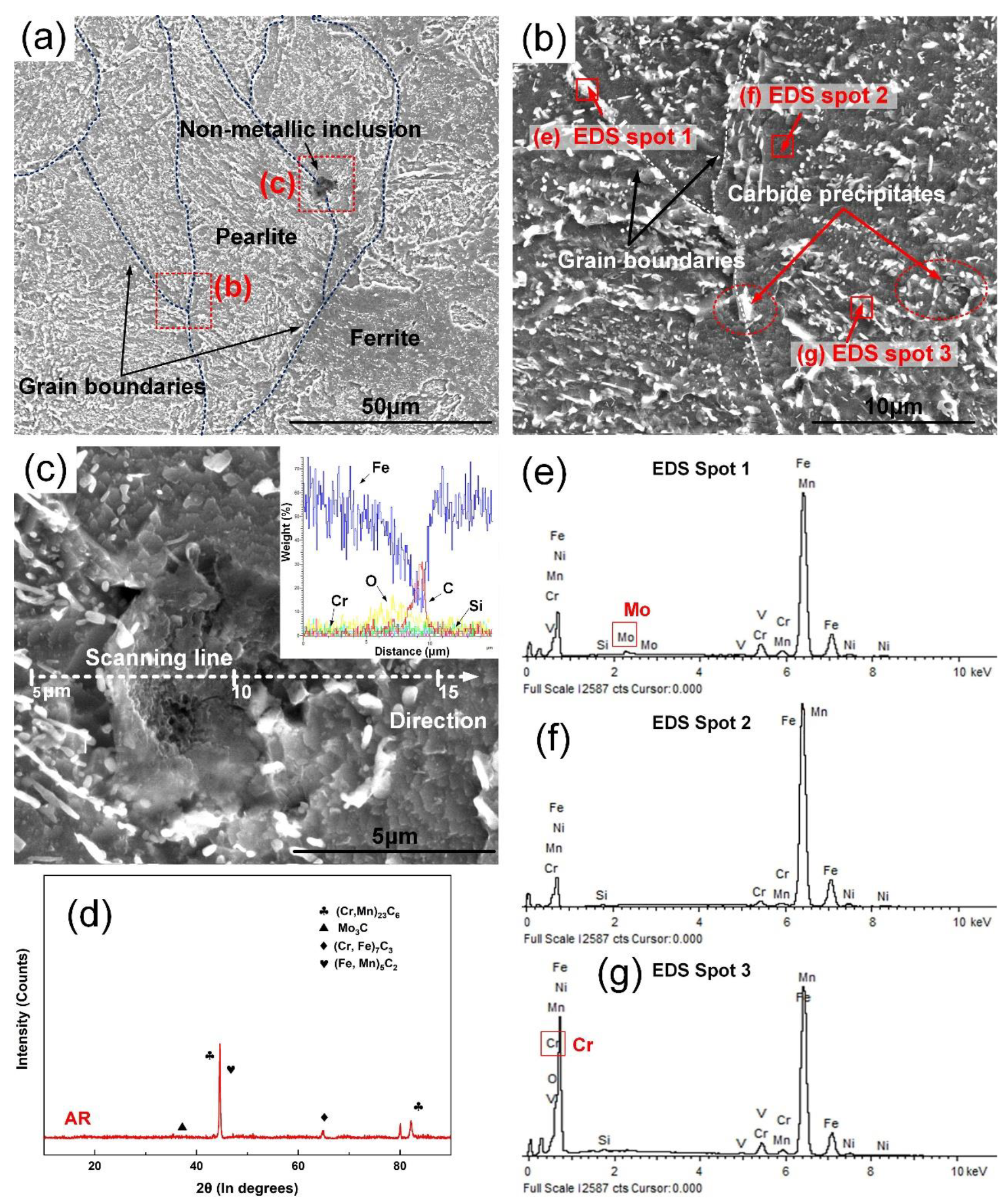
3.3.1. Initial Microstructure under As-Received State (AR)

Through the analysis of microstructure, it is possible to clarify the in-depth relationship between the structure compositions and the wear behaviors under different tempering states. Figure 10 presents the SEM micrographs, EDS and XRD spectra of the 25CrNi2MoVE steel surface under AR state. It can be seen from Figure 10a,b that the microstructures of the etched surface are spherical pearlite formed by the distribution of granular carbide precipitate and small short bar-like carbide precipitate on the ferritic matrix. These small short bar-like carbide precipitates are arranged in parallel chains, which belong to good spheroidizing annealing structure. The measured sizes of the carbide precipitates on grain boundary and matrix were 1.02 ± 0.28 μm and 0.35 ± 0.09 μm, respectively. In addition to spherical pearlite, a small amount of gray ferrite and black non-metallic inclusions are observed between the pearlite. A large amount of coarse grain pearlite and ferrite makes the low hardness and good ductility of material, so that the abrasive particles are more likely to adhere to the surface of the upper sample and then will be carried away from the matrix [29]. Meanwhile, the lower hardness will also bring about severe plastic deformation, and the accompanying surface modification layer can lead to reduction of the CoF [30]. The inter-grain boundaries in AR state are highlighted as dashed lines in Figure 10a. Distinctly, at the initial stage of wear, larger grains make the grain boundary fracture and brittle grain pull-out more pronounced [31]. Based on the fixed-point EDS analysis of grain boundary, matrix and carbide precipitates on the matrix surface, it is found that the their compositions are basically similar and rich in Fe, Cr, Ni and Mn (Figure 10e–g). Simultaneously, the peak intensity of the Cr element in carbide precipitates on the grain boundary and matrix surface is significantly higher than that of the matrix. Combined with the surface XRD results in Figure 10d, it can be clarified that the types of carbide on the sample surface mainly include Fe and Mo-rich M3C, Fe and Cr-rich M7C3, Cr and Mn-rich M23C6 and Cr-rich M3C2. Therefore, according to the dilution effect, it can be inferred that the supersaturated carbon in the steel diffuses to the grain boundary and precipitate, and the Cr-rich Cr23C6 carbides were formed with the Cr element near it. The slow diffusion rate of the Cr element in grains also explains the significant reduction in Cr element concentration in the matrix surrounding the Cr-rich carbide precipitated along grain boundaries. A higher peak intensity of Mo element can be found in EDS spot 1 than that in EDS spot 3, which indicates the possible existence of Mo-rich Mo3C and Mo3C2 carbides on grain boundaries (Figure 10e).
In addition, a small number of black non-metallic inclusions with diameters of about 7.07 ± 2.35 µm around the grain boundaries ca be seen (Figure 10a). Based on EDS line scanning results in Figure 10c, it is found that the content of Fe element in non-metallic inclusion decreased sharply, and the content of C, O and Si increased. Guo et al. [32] noticed that the modified oxidized inclusions will be used as the core of nonhomogeneous nucleation in steel with the decrease of temperature; meanwhile, a layer of carbide will be formed outside the oxidized inclusions due to the easily segregated carbon elements in steel. Thereby, the observed non-metallic inclusions should consist of a mixture of oxides and carbides. This may be not beneficial to the wear resistance of steel [33].

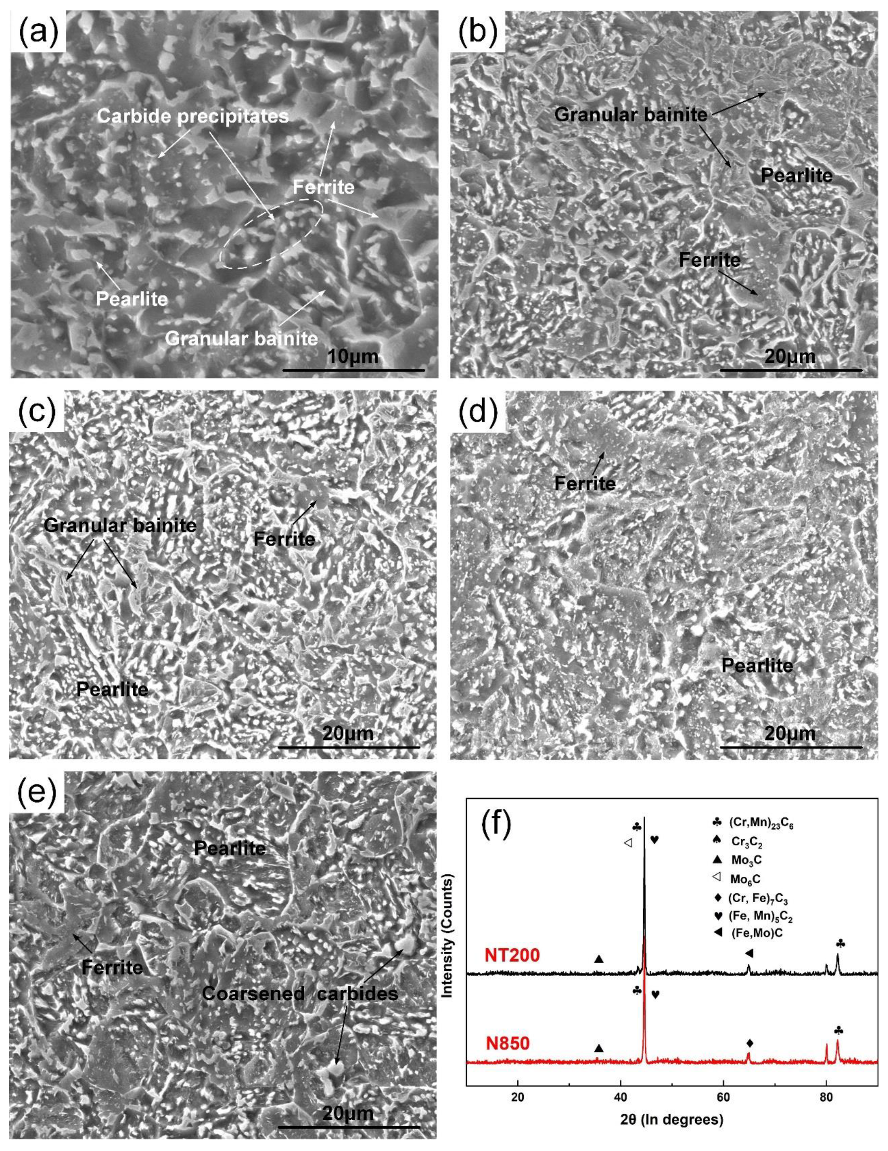
3.3.2. Tempered Microstructure after Normalizing (N850, NT200, NT350, NT550, NT850)

Tempering for normalized components, for many types of alloy steel, can also obtain an excellent performance that meets the requirements and be used directly, especially for some large-section components of the shaft type. Figure 11 shows the SEM micrographs of normalized samples after tempering under different temperatures. The evenly distributed polygonal netted ferrite, pearlite and a few granular bainite can be found after normalizing at 850 °C (Figure 11a). Bainite is considered to have good anti-wear properties, so it plays a positive role in reducing the wear rate [34]. Short, white bar-like particles with an average size of 0.67 ± 0.25 µm are observed in the matrix and grain boundary. As seen in the XRD patterns in Figure 11f, compared with the AR state, the grain size was refined by 81.39%, the M23C6 netted carbides were dissolved and the Fe-rich M5C2 phase was precipitated. Among them, M5C2 carbide has been proven to have excellent wear resistance [35]. After tempering at 200 °C, the microstructure was transformed into ferrite, pearlite and the granular bainite left behind after normalizing (Figure 11b). Low temperature tempering refined bainite grains and introduced more higher-angle boundaries, which helps to enhance the wear resistance of the substrate [36]. As can be seen from Figure 11f, the M23C6 phase was precipitated again, the M3C2 phase and M6C phase were precipitated at the same time. It indicates that M3C and M5C2 have good stability, so they can be retained [37]. In addition, Singh et al. [38] also found that the fine distribution of metastable M6C carbides improved the wear resistance of metals. With tempering at 350 °C, granular bainite gradually became smaller and uniformly distributed (Figure 11c). It can be inferred that the driving force of the transformation from residual austenite to bainite decreases, resulting in the decrease of hardness and the increase of the CoF and Kv value. With tempering at 550 °C, the bainite disappeared in the microstructure, leaving residual ferrite and pearlite (Figure 11d). Simultaneously, no obvious complete grain boundary was found, and a large number of fine carbides were precipitated on the surface. In comparison with tempering after quenching, the large number of fine carbides produced by tempering at high temperature after normalizing do not appear to increase the hardness. The excess carbide precipitate may also be responsible for the high Kv value. Furthermore, the lower hardness reduces the work hardening tendency, and the surface materials are prone to directional flow under the action of shear force, which indirectly reduces the WSR. When the tempering temperature reaches 850 °C, it can be regarded as secondary normalizing (Figure 11e). The microstructure is mainly netted ferrite and pearlite, and obvious grain boundaries appear. The grain size of ferrite increases accordingly, reaching 13.82 ± 2.8 µm, and the average diameter of carbide precipitates increases to 1.62 ± 0.99 µm. Laha et al. [39] also observed finer austenite grain size and coarsened MX precipitates after secondary normalizing of 9Cr1Mo steel. As the average diameter of spherical carbide precipitates increases, the hardness of the microstructures decreases [40]. Therefore, even if the hardness decreases, the presence of grain boundaries can improve the wear performance of materials.

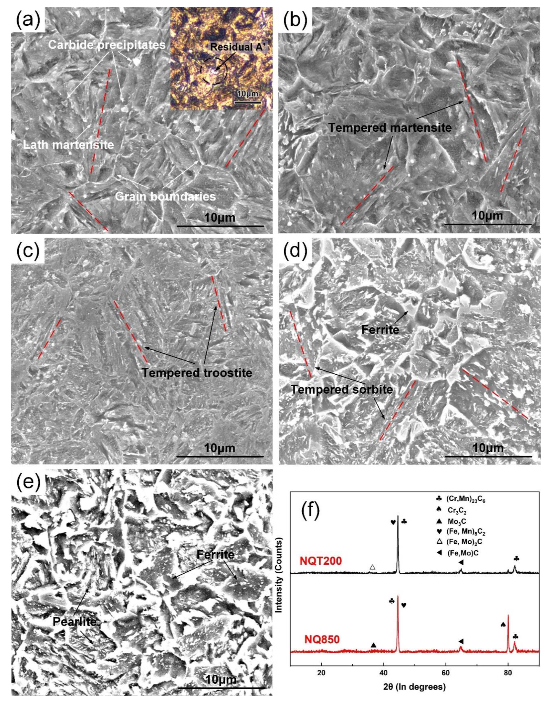
3.3.3. Tempered Microstructure after Quenching (NQ850, NQT200, NQT350, NQT550, NQT850)

Figure 12 shows the SEM micrographs of quenched samples after tempering under different temperatures. The microstructure observed after quenching was mainly lath quenched martensite separated by the prior austenite grain boundaries, and a small amount of white residual austenite (A’) was sandwiched between the needles (Figure 12a). There are a few precipitated spherical carbide precipitates with a size of about 0.71 ± 0.13 μm on the grain boundaries and martensite surface. Compared with AR state, the M2C and M5C2 carbides were increased (Figure 12f). The existence of M2C phase can obviously improve the hardness and fracture toughness of steel and improve the wear resistance [41]. Furthermore, according to the Hall–Petch effect, the material strength will be increased due to the dislocation movement blocked by grain boundaries and the presence of a large number of fine grains [42]. The multi-phase structure composed of martensite and residual austenite can obtain high strength and toughness so that the Kv value can be significantly reduced. However, it is observed that the CoF of the sample was significantly higher than that of the AR state after quenching, which may be caused by the presence of hard asperity on both surfaces. Because it is more difficult for the surface material to be peeled off and form debris, the WSR of the tribo-pair decreases accordingly. Even though the hard-hard contact pair can bring a smaller amount of wear, an excessively large CoF is not beneficial for the transmission efficiency of the component.
As shown in Figure 12b, after tempering at 200 °C, the microstructure is tempered martensite and a small amount of residual austenite. Based on the XRD patterns, it is found that the M3C2 and M2C phases are partly dissolved, which will slightly affect the hardness. Importantly, due to the formation of a tempered martensite structure, the fracture toughness, fatigue strength and plasticity can be improved. Cui et al. [43] reported that wear resistance is proportional to fracture resistance. Therefore, the microstructure after low temperature tempering is beneficial to improve the wear loss, and the slight plastic deformation ability also reduces the CoF. With tempering at 350 °C, the martensite is transformed into a tempered troostite with a strip shape, and granular carbides gradually precipitate and grow (Figure 12c). The presence of troostite is believed to be beneficial to improving the elastic limit, yield limit and toughness of steel [44]. According to the test results, the tempered troostite phase presents a more positive influence on the fretting wear properties of quenched 25CrNi2MoVE steel, and both the Kv value and CoF are at the lowest level of the series tempering temperature. Wang et al. [45] mentioned the existence of secondary carbides (such as (Cr, Fe)7C3 and Mo2C) with good stability in troostite, which had a great influence on reducing the oxidation wear rate of the material surface. With tempering at 550 °C, the microstructure is primarily tempered sorbite. The morphology of lathes was merged and no longer obvious. Simultaneously, some dislocation occurred static recovery, the density decreased, the content of polygonal ferrite increased and a large number of Cr-rich (Fe, Cr)C carbides (size of 0.15~0.49 μm) were precipitated on the matrix (Figure 12d). This is beneficial to improve the plasticity of steel but will inevitably bring about a reduction in hardness and strength [46]. The softened steel makes the surface more prone to adhesive wear, and the increased contact area also increases the CoF. Similar to the NT550 state, the WSR is reduced. With tempering at 850 °C, the microstructure shows a multi-phase structure composed of ferrite and the pearlite with martensite lath orientation (Figure 12e). Meanwhile, a large number of carbides precipitated along and within the grain boundaries, which will further reduce the hardness and strength of the materials, and the increase of particle size will also weaken the effect of precipitation strengthening on wear resistance [47].

3.4. Wear Mechanisms

Figure 13 shows the SEM worn morphologies of 25CrNi2MoVE steel under different material states. The double arrow lines in the figure indicate the direction of fretting wear and the arcuate dashed line describe the distribution of debris accumulation during the fretting wear test. As can be seen from the figure, the surface of each sample has different degrees of flake-like abrasions layer and ploughings, and some wear debris accumulate at both ends to form accumulation areas. Meanwhile, a small number of spalling pits and granular abrasive particles are distributed sporadically.
In AR state, it can be seen that the wear degree is obviously more serious, and the wear debris is superimposed in layers (Figure 13a). Through the partial enlargement of the worn surface, a ladder resulting from the fracture of the edge of the adhesive layer is found (Figure 13b). Below the ladder is the ploughing structure formed in the last wear sliding cycle, with a maximum width of about 5.4 μm. The results show that serious metal plastic deformation occurs on the sample surface, and the transferred debris is rebonded with the surface under the action of pressure. This serious adhesive wear phenomenon is mainly attributed to the low hardness and coarse grain structure of the material in AR state. The ploughing structure and free debris indicated the existence of abrasive wear. The formation of abrasive debris is periodic; the micro-cracks perpendicular to the fretting direction are observed on the surface of the adhesive layer, which means that when the wear develops further, the material will break again along the crack and re-form the new wear debris. Due to the presence of the third agent besides the upper and lower samples, the abrasive debris, it is also known as “third-body wear”. In some cases, third-body wear is considered beneficial to wear resistance [48], but from this work it is clear that third-body wear promotes surface wear when the substrate is of low hardness and has severe adhesive wear. Meanwhile, non-metallic inclusions have been proven to act as stress raisers in the primary shear zone [49], which may promote abrasive wear degree of the material in AR state. EDS spot 4 and EDS spot 5 show the qualitative elementary analysis results of the unworn surface and the transferred debris on the worn surface, respectively (Figure 13c,d). It can be found that there are a large number of oxygen elements in the transferred debris, indicating that there are oxidation products such as FeO, Fe2O3 or Fe3O4. A large number of black oxide films observed on the surface of the adhesive layer indicate the presence of corrosion wear.
Figure 13e–n illustrates the fretting morphologies of samples under different tempering states. Compared with the AR state, the significant refinement of the grains after normalizing improves the strength of the material, which makes ploughings on the surface of the samples shallower, and the spalling pits are significantly reduced. Improvement of toughness makes a plastic deformation layer continuously exist on the worn surface, which has good anti-spalling performance and effectively reduces the wear caused by direct contact with the matrix. As a result, the resistance of adhesive wear and fatigue wear can be improved.
After tempering at 200 °C, a white hardened layer is observed, and the adhesive layer reduced significantly, which is replaced by a large number of free abrasive particles evenly distributed. Similar to what Bakshi et al. [50] mentioned, the bainite was generated after tempering produces strong strain hardening on the worn surface, resulting in the formation of a white hardening layer, which forms a large number of free brittle abrasive particles after further fracture. Liu et al. [51] reported that the loosely attached powder could have played an important role in slowing the wear debris and makes the wear depth change flatten out. Therefore, abrasive wear became the main wear mechanism in NT200 state, accompanied by slight adhesive wear and corrosion wear.
As the tempering temperature continued to increase, the hardness of the material decreased, and the adhesive wear also increased. With tempering at 350 °C, a large number of small fatigue spalling pits can be observed. This indicates that although the digestion of bainite reduces the tendency of work hardening, and abrasive wear still forms between the tribo-pair surfaces. At the same time, the decrease of hardness makes the degree of adhesive wear increase obvious. When tempering at 550 °C, the large amounts of ferrite and missing grain boundaries make the surface material more prone to slip and flow, while the accumulation of soft substrate makes the edge of the wear scar more obvious and the WSR is lower than that of NT350. The wear mechanism is mainly classified as adhesive wear, and a small amount of debris indicates the existence of abrasive wear. At 850 °C, the big ferrite grains and carbide particle sizes softened the material and caused severe adhesive wear; therefore, a more obvious wear scar edge can be seen.
Similar to the state after normalizing, the material strength and hardness are greatly improved by the formation of a martensite structure. The few adhesive layers on the worn surface indicate that the fatigue wear and adhesive wear are relatively light. It can also be seen from the CoF curve under NQ850 state in Figure 4a that the tribo-pair went through a long three-body contact stage (slow decrease in CoF) before reaching the steady wear stage. This means that the spalling of surface asperity has gone through a long process, and the dominated wear mechanism is abrasive wear. After tempering at 200 °C, a larger smooth area is observed, with less adhesive layer and short rod-shaped debris distribution on the surface. The decrease of the adhesive layer is due to the decrease of plastic deformation capacity caused by the tempered martensite structure with high hardness and fracture toughness, which makes spalling unable to rebond to the sample surface. At this time, the hardness of the substrate is higher, and the three-body wear is helpful to isolate the tribo-pair surface and reduce the wear. With tempering at 350 °C, tempered troostite reduces the surface hardness of the material, and the increased WSR and a large number of adhesive layers reflect the aggravation of adhesive wear. However, the continuous existence of these adhesive layers indicates that they are more difficult to be broken, i.e., fatigue wear and oxidative wear are inhibited. This is consistent with the previous analysis that these adhesive layers with good fracture toughness can effectively isolate the direct contact between metal substrates. Therefore, even if the WSR is high in NQT350 state, the wear mechanisms are still mainly abrasive wear and adhesive wear. Tempering at 550 °C, adhesive wear and fatigue wear predominate. Since the tempered sorbite retains a certain hardness, some of fine debris can still be observed, which is then discharged externally and accumulated at both ends of the worn surface. However, it is obvious that the soft matrix can’t support the fine debris on the surface for a long time to form a beneficial “third-body wear”. With tempering at 850 °C, the microstructure was all transformed into ferrite and pearlite, the hardness decreased significantly, and the adhesive wear contributed more in the fretting wear mechanism than in the NQT550 state.

4. Conclusions

In this work, the fretting wear behaviors and wear mechanisms of 25CrNi2MoVE steel under different tempering states were studied through an oscillating friction and wear tester. The main conclusions can be summarized as follows.
  • In AR state (spheroidization annealing), coarse ferrite grain, pearlite grain and carbide precipitates are the main reasons for the low wear resistance.
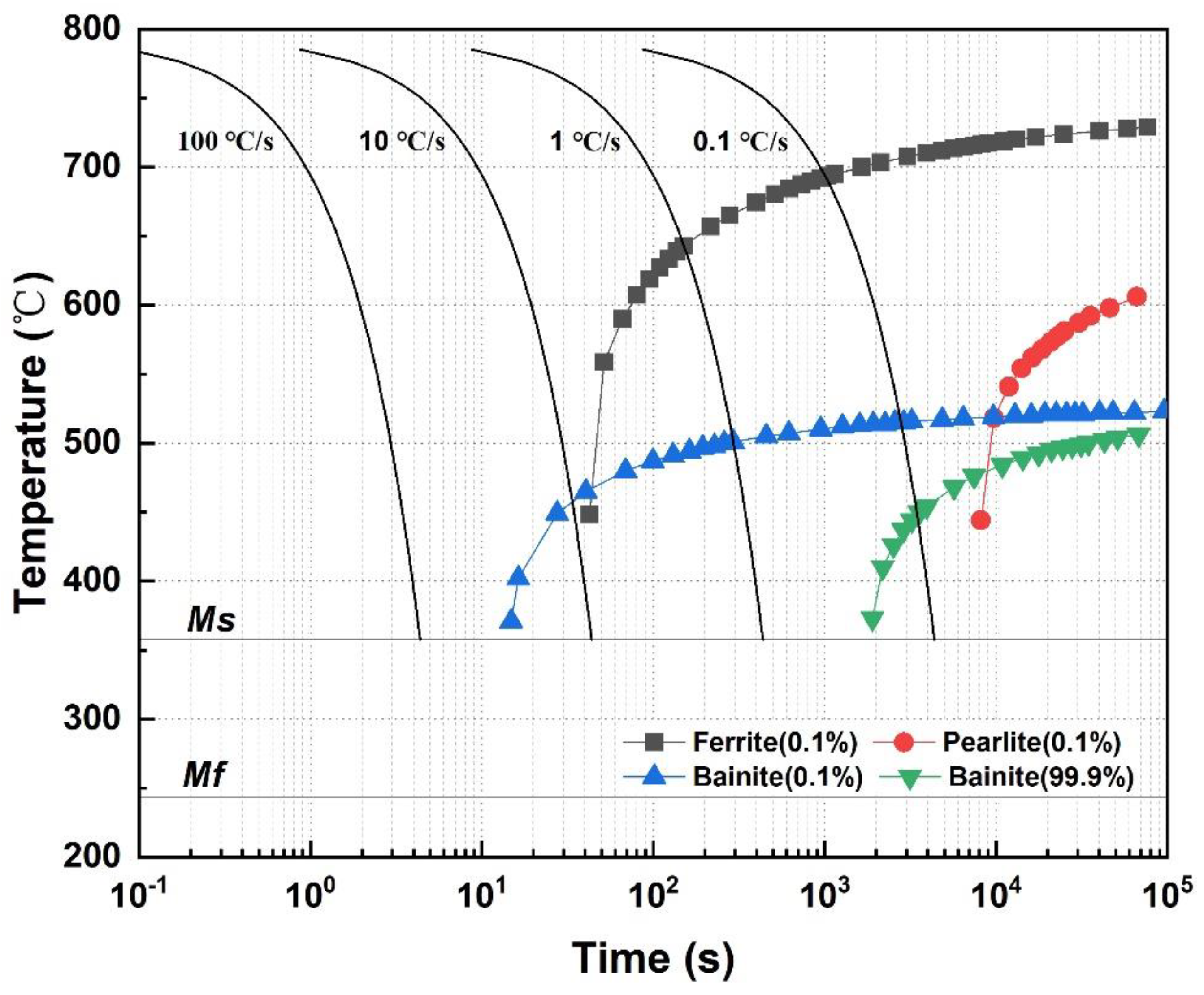
  • Normalizing significantly reduced the grain and carbide precipitate size of the original material and obtained the beneficial M5C2 phase and a low worn surface roughness. Tempering at 200 °C can promote the formation and refinement of bainite, and the presence of metastable M6C, M3C and M5C2 carbides can also improve wear performances. From 350 °C to 850 °C, bainite gradually reduced or dissolved, grain boundary disappeared and volumetric wear rate, coefficient of friction and worn surface roughness increased.
  • Martensite multi-phase structure and M2C and M5C2 carbides can be generated by quenching to improve wear resistance and worn surface roughness. After tempering at 200 °C, the tempered martensite structure was obtained, which effectively alleviated the fatigue wear problems. When tempering at 350 °C, the tempered troostite increased the degree of adhesive wear and worn surface roughness, but the good continuity of surface oxide film provides good wear resistance. The excessive tempering temperature resulted in the decrease of material strength and deterioration of volumetric wear rate.
  • In AR state, the coarse grain caused an easy slip tendency, leading to a high adhesive wear and fatigue wear degree. After normalizing, the grains are refined, and the fatigue wear is improved accordingly. As the tempering temperature increased, the hardness and work hardening tendency decreased and the degree of abrasive wear gradually decreased. For quenched samples, the staggered lath martensite structure greatly enhanced the hardness, and adhesive wear and fatigue wear became the main mechanisms. As the tempering temperature increased, fatigue wear improved. Abrasive wear tends to increase first and then decrease, and adhesive wear gradually becomes the main wear mechanism.

Author Contributions

Conceptualization, X.H. and S.Q.; methodology, F.L.; software, X.H.; validation, F.L., X.H. and S.Q.; formal analysis, Y.Z.; investigation, Z.W.; resources, H.L.; data curation, X.H.; writing—original draft preparation, X.H. and F.L.; writing—review and editing, X.H. and F.L.; visualization, Y.Z. and X.H.; supervision, H.L.; project administration, S.Q.; funding acquisition, S.Q. All authors have read and agreed to the published version of the manuscript.

Funding

This research was funded by the Open Fund Project of National Engineering Research Centre of Near-net-shape Forming Technology for Metallic Materials, the Key Laboratory of High Efficient Near-Net-Shape Forming Technology and Equipments for Metallic Materials, Ministry of Education, China (category B) [2019002] and Open Fund Project of State Key Laboratory of Engine Reliability [SKLER-201705].

Acknowledgments

The authors acknowledge the State Key Laboratory of Smart Manufacturing for Special Vehicle and Transmission System in material preparation and mechanical properties test.

Conflicts of Interest

The authors declare no conflicts of interest.

Nomenclature

Ac1start temperature of pearlite to austenite transformation during heating [°C]Ac3finish temperature of ferrite to austenite transformation during heating [°C]
Msmartensite start temperature during cooling [°C]Mfmartensite finish temperature during cooling [°C]
Vvolumetric wear loss [mm3]hmaximum depth of the fretting wear scar on lower sample [mm]
ρapproximate curvature radius of the wear scar concave surfacelmaximum length of the wear scar along the fretting direction [mm]
dmaximum width of the wear scar perpendicular to the fretting direction [mm]Kvvolumetric wear rate [mm3/Nm]
FNimposed normal contact force [N]srelative slip distance [m]

References

  1. Ding, J.; Leen, S.B.; McColl, I.R. The effect of slip regime on fretting wear-induced stress evolution. Int. J. Fatigue 2004, 26, 521–531. [Google Scholar] [CrossRef]
  2. Alfredsson, B. Fretting fatigue of a shrink-fit pin subjected to rotating bending: Experiments and simulations. Int. J. Fatigue 2009, 31, 1559–1570. [Google Scholar] [CrossRef]
  3. Zeise, B.; Liebich, R.; Prölß, M. Simulation of fretting wear evolution for fatigue endurance limit estimation of assemblies. Wear 2014, 316, 49–57. [Google Scholar] [CrossRef]
  4. Wang, S.; Wang, F.; Liao, Z.; Wang, Q.; Liu, Y.; Liu, W. Study on torsional fretting wear behavior of a ball-on-socket contact configuration simulating an artificial cervical disk. Mat. Sci. Eng. 2015, 55, 22–33. [Google Scholar] [CrossRef] [PubMed]
  5. De Martino, I.; Assini, J.B.; Elpers, M.E.; Wright, T.M.; Westrich, G.H. Corrosion and fretting of a modular hip system: A retrieval analysis of 60 rejuvenate stems. J. Arthroplasty 2015, 30, 1470–1475. [Google Scholar] [CrossRef] [PubMed]
  6. Hyde, T.R.; Leen, S.B.; McColl, I.R. A simplified fretting test methodology for complex shaft couplings. Fatigue Fract. Eng. Mater. Struct. 2005, 28, 1047–1067. [Google Scholar] [CrossRef]
  7. Bensely, A.; Senthilkumar, D.; Lal, D.M.; Nagarajan, G.; Rajadurai, A. Effect of cryogenic treatment on tensile behavior of case carburized steel-815M17. Mater. Charact. 2007, 58, 485–491. [Google Scholar] [CrossRef]
  8. Tan, L.; Crone, W.C.; Sridharan, K. Fretting wear study of surface modified Ni–Ti shape memory alloy. J. Mater. Sci. Mater. Med. 2002, 13, 501–508. [Google Scholar] [CrossRef]
  9. Deshpande, P.K.; Lin, R.Y. Wear resistance of WC particle reinforced copper matrix composites and the effect of porosity. Mat. Sci. Eng. A Struct. 2006, 418, 137–145. [Google Scholar] [CrossRef]
  10. Aiguo, W.; Rack, H.J. Abrasive wear of silicon carbide particulate—and whisker-reinforced 7091 aluminum matrix composites. Wear 1991, 146, 337–348. [Google Scholar] [CrossRef]
  11. Fischer, T.E.; Zhu, Z.; Kim, H.; Shin, D.S. Genesis and role of wear debris in sliding wear of ceramics. Wear 2000, 245, 53–60. [Google Scholar] [CrossRef]
  12. Kesavan, D.; Kamaraj, M. The microstructure and high temperature wear performance of a nickel base hardfaced coating. Surf. Coat. Tech. 2010, 204, 4034–4043. [Google Scholar] [CrossRef]
  13. Xu, L.; Wei, S.; Xiao, F.; Zhou, H.; Zhang, G.; Li, J. Effects of carbides on abrasive wear properties and failure behaviours of high speed steels with different alloy element content. Wear 2017, 376, 968–974. [Google Scholar] [CrossRef]
  14. Wang, Q.; Li, X. Effects of Nb, V, and W on microstructure and abrasion resistance of Fe-Cr-C hardfacing alloys. Weld. J. 2010, 89, 133–139. [Google Scholar]
  15. Hussainova, I. Effect of microstructure on the erosive wear of titanium carbide-based cermets. Wear 2003, 255, 121–128. [Google Scholar] [CrossRef]
  16. Sahin, Y.; Erdogan, M.; Cerah, M. Effect of martensite volume fraction and tempering time on abrasive wear of ferritic ductile iron with dual matrix. Wear 2008, 265, 196–202. [Google Scholar] [CrossRef]
  17. Wei, M.X.; Wang, S.Q.; Wang, L.; Cui, X.H.; Chen, K.M. Effect of tempering conditions on wear resistance in various wear mechanisms of H13 steel. Tribol. Int. 2011, 44, 898–905. [Google Scholar] [CrossRef]
  18. Coronado, J.J.; Gómez, A.; Sinatora, A. Tempering temperature effects on abrasive wear of mottled cast iron. Wear 2009, 267, 2070–2076. [Google Scholar] [CrossRef]
  19. Chen, G.X.; Zhou, Z.R. Study on transition between fretting and reciprocating sliding wear. Wear 2001, 250, 665–672. [Google Scholar] [CrossRef]
  20. Hu, X.; Xie, L.; Gao, F.; Xiang, J. On the Development of Material Constitutive Model for 45CrNiMoVA Ultra-High-Strength Steel. Metals 2019, 9, 374. [Google Scholar] [CrossRef] [Green Version]
  21. Perenda, J.; Trajkovski, J.; Žerovnik, A.; Prebil, I. Modeling and experimental validation of the surface residual stresses induced by deep rolling and presetting of a torsion bar. Int. J. Mater. Form. 2016, 9, 435–448. [Google Scholar] [CrossRef]
  22. Liu, T.; Shi, X.; Zhang, J.; Fei, B. Crack initiation and propagation of 30CrMnSiA steel under uniaxial and multiaxial cyclic loading. Int. J. Fatigue 2019, 122, 240–255. [Google Scholar] [CrossRef]
  23. Segerstark, A.; Andersson, J.; Svensson, L.; Ojo, O. Microstructural characterization of laser metal powder deposited Alloy 718. Mater. Charact. 2018, 142, 550–559. [Google Scholar] [CrossRef]
  24. Barralis, J.; Maeder, G. Métallurgie-Tome I: Métallurgie Physique; Collection Scientifique ENSAM; Communications Actives: Paris, France, 1982; p. 270. [Google Scholar]
  25. Yan, F.; Zhou, H. Measurement and calculation of wear volume of ball-disk fretting wear parts. Tribology 1995, 15, 145–151. [Google Scholar]
  26. Bonny, K.; De Baets, P.; Vleugels, J.; Huang, S.; Van der Biest, O.; Lauwers, B. Impact of Cr3C2/VC addition on the dry sliding friction and wear response of WC–Co cemented carbides. Wear 2009, 267, 1642–1652. [Google Scholar] [CrossRef]
  27. Radhika, N.; Subramaniam, R. Machining parameter optimisation of an aluminium hybrid metal matrix composite by statistical modelling. Ind. Lubr. Tribol. 2013, 65, 425–435. [Google Scholar] [CrossRef]
  28. Cui, X.H.; Wang, S.Q.; Wang, F.; Chen, K.M. Research on oxidation wear mechanism of the cast steels. Wear 2008, 265, 468–476. [Google Scholar] [CrossRef]
  29. Man, H.C.; Zhang, S.; Cheng, F.T. Improving the wear resistance of AA 6061 by laser surface alloying with NiTi. Mater. Lett. 2007, 61, 4058–4061. [Google Scholar] [CrossRef]
  30. Zhao, A.; Xie, J.; Sun, C.; Lei, Z.; Hong, Y. Effects of strength level and loading frequency on very-high-cycle fatigue behavior for a bearing steel. Int. J. Fatigue 2012, 38, 46–56. [Google Scholar] [CrossRef] [Green Version]
  31. Krell, A. Improved hardness and hierarchic influences on wear in submicron sintered alumina. Mat. Sci. Eng. A Struct. 1996, 209, 156–163. [Google Scholar] [CrossRef]
  32. Guo, J.; Cheng, S.; Cheng, Z.; Zhang, Y. Study on precipitation of carbonized inclusions during solidification of low carbon aluminum killed steel. In Proceedings of the Baosteel Biennial Academic Conference Meeting Steel’s New Challenges, Baosteel BAC, Shangai, China, 4–6 June 2013. [Google Scholar]
  33. Halila, F.; Czarnota, C.; Nouari, M. Analytical stochastic modeling and experimental investigation on abrasive wear when turning difficult to cut materials. Wear 2013, 302, 1145–1157. [Google Scholar] [CrossRef]
  34. Vélez, J.M.; Tanaka, D.K.; Sinatora, A.; Tschiptschin, A.P. Evaluation of abrasive wear of ductile cast iron in a single pass pendulum device. Wear 2001, 251, 1315–1319. [Google Scholar] [CrossRef] [Green Version]
  35. Jain, N.C.; Patwardhan, A.K. Effect of heat treatment on the hardness-microstructure inter-relation in a 7.5Mn-5Cr-1.5Cu alloy white iron: A modeling approach. Metall. Mater. Trans. A 1992, 23, 891–901. [Google Scholar] [CrossRef]
  36. Lan, H.F.; Du, L.X.; Li, Q.; Qiu, C.L.; Li, J.P.; Misra, R.D.K. Improvement of strength-toughness combination in austempered low carbon bainitic steel: The key role of refining prior austenite grain size. J. Alloy. Compd. 2017, 710, 702–710. [Google Scholar] [CrossRef]
  37. Mann, S.D.; McCulloch, D.G.; Muddle, B.C. Identification of M5C2 carbides in ex-service 1Cr-0.5 Mo steels. Metall. Mater. Trans. A 1995, 26, 509. [Google Scholar] [CrossRef]
  38. Singh, J.; Mazumder, J. Microstructure and wear properties of laser clad Fe-Cr-Mn-C alloys. Metall. Mater. Trans. A 1987, 18, 313–322. [Google Scholar] [CrossRef]
  39. Laha, K.; Chandravathi, K.S.; Parameswaran, P.; Rao, K.B.S.; Mannan, S.L. Characterization of microstructures across the heat-affected zone of the modified 9Cr-1Mo weld joint to understand its role in promoting type IV cracking. Metall. Mater. Trans. A 2007, 38, 58–68. [Google Scholar] [CrossRef]
  40. De Castro, V.; Leguey, T.; Munoz, A.; Monge, M.A.; Fernández, P.; Lancha, A.M.; Pareja, R. Mechanical and microstructural behaviour of Y2O3 ODS EUROFER 97. J. Nucl. Mater. 2007, 367, 196–201. [Google Scholar] [CrossRef]
  41. Casellas, D.; Caro, J.; Molas, S.; Prado, J.M.; Valls, I. Fracture toughness of carbides in tool steels evaluated by nanoindentation. Acta Mater. 2007, 55, 4277–4286. [Google Scholar] [CrossRef]
  42. Arzt, E. Size effects in materials due to microstructural and dimensional constraints: A comparative review. Acta Mater. 1998, 46, 5611–5626. [Google Scholar] [CrossRef] [Green Version]
  43. Cui, X.H.; Wang, S.Q.; Wei, M.X.; Yang, Z.R. Wear characteristics and mechanisms of H13 steel with various tempered structures. J. Mater. Eng. Perform. 2011, 20, 1055–1062. [Google Scholar] [CrossRef]
  44. Hu, Y.; Tian, J.; Xu, M.; Zhao, H.; Wang, M.; Wang, M.; Zhang, A. The Preparation of H13 Steel for TBM Cutter and the Performance Test Close to Working Condition. Appl. Sci. 2018, 8, 1877. [Google Scholar] [CrossRef] [Green Version]
  45. Wang, S.Q.; Wang, F.; Cui, X.H.; Chen, K.M. Effect of secondary carbides on oxidation wear of the Cr–Mo–V cast steels. Mater. Lett. 2008, 62, 279–281. [Google Scholar] [CrossRef]
  46. Yan, G.; Huang, X.; Wang, Y.; Qin, X.; Yang, M.; Chu, Z.; Jin, K. Effects of heat treatment on mechanical properties of H13 steel. Met. Sci. Heat. Treat 2010, 52, 393–395. [Google Scholar]
  47. Dhua, S.K.; Ray, A.; Sarma, D.S. Effect of tempering temperatures on the mechanical properties and microstructures of HSLA-100 type copper-bearing steels. Mat. Sci. Eng. A Struct. 2001, 318, 197–210. [Google Scholar] [CrossRef]
  48. Ghosh, A.; Wang, W.; Sadeghi, F. An elastic–plastic investigation of third body effects on fretting contact in partial slip. Int. J. Solids Struct. 2016, 81, 95–109. [Google Scholar] [CrossRef]
  49. Ånmark, N.; Björk, T. Tool wear in soft part turning of high performance steel. Procedia CIRP 2016, 46, 484–487. [Google Scholar] [CrossRef] [Green Version]
  50. Bakshi, S.D.; Shipway, P.H.; Bhadeshia, H. Three-body abrasive wear of fine pearlite, nanostructured bainite and martensite. Wear 2013, 308, 46–53. [Google Scholar] [CrossRef] [Green Version]
  51. Liu, G.; Chen, Y.; Li, H. A study on sliding wear mechanism of ultrahigh molecular weight polyethylene/polypropylene blends. Wear 2004, 256, 1088–1094. [Google Scholar] [CrossRef]
Figure 1. The continuous cooling transition (CCT) curves of 25CrNi2MoVE steel.
Metals 10 00351 g001
Figure 2. Schematic diagram of the test rig for fretting wear.
Metals 10 00351 g002
Figure 3. Roughness measurements: (a) cross-section scanning of fretting wear scar and (b) measuring of worn surface roughness (WSR).
Metals 10 00351 g003
Figure 4. The fretting CoF of 25CrNi2MoVE steel under different tempering states: (a) under AR, N850 and NQ850 states, (b) under NT200, NT350, NT550 and NT850 states, (c) under NQT200, NQT350, NQT550 and NQT850 states, (d) steady CoF.
Metals 10 00351 g004
Figure 5. Optical morphologies of worn surface under different tempering states: (a) AR state, (b) N850, (c) NT200, (d) NT350, (e) NT550, (f) NT850, (g) NQ850, (h) NQT200, (i) NQT350, (j) NQT550 and (k) NQT850 states.
Metals 10 00351 g005
Figure 6. 3D morphologies of worn surface under different tempering states: (a) AR state, (b) N850, (c) NT200, (d) NT350, (e) NT550, (f) NT850, (g) NQ850, (h) NQT200, (i) NQT350, (j) NQT550 and (k) NQT850 states.
Metals 10 00351 g006
Figure 7. The variation of Kv value under different tempering temperature.
Metals 10 00351 g007
Figure 8. Variation of WSR under different material states.
Metals 10 00351 g008
Figure 9. Variation of microhardness under different tempering states.
Metals 10 00351 g009
Figure 10. Scanning electron microscope (SEM) micrographs of 25CrNi2MoVE steel under AR state: (a) at 2500× and (b) 10000× magnification; (c) Energy dispersive spectrometer (EDS) line scanning spectrum of non-metallic inclusion; (d) surface X-ray diffraction (XRD) pattern under AR state; (e) EDS spectrum of EDS spot 1 (carbide precipitates on grain boundaries), (f) EDS spot 2 (ferritic matrix) and (g) EDS spot 3 (carbide precipitates inside grain boundaries).
Metals 10 00351 g010
Figure 11. Effect of different tempering temperature on microstructure of normalized sample: (a) no tempering (N850), (b) at 200 °C (NT200), (c) at 350 °C (NT350), (d) at 550 °C (NT550), (e) at 850 °C (NT850); (f) X-ray diffraction (XRD) patterns under N850 and NT200 states.
Metals 10 00351 g011
Figure 12. Microstructure of quenched steel after tempering at different temperatures: (a) no tempering (NQ850), (b) at 200 °C (NQT200), (c) at 350 °C (NQT350), (d) at 550 °C (NQT550), (e) at 850 °C (NQT850); (f) X-ray diffraction (XRD) patterns under NQ850 and NQT200 states.
Metals 10 00351 g012
Figure 13. Scanning electron microscope (SEM) morphologies and energy spectra of worn surface: magnification of AR state (a) at 400× and (b) at 1600×; Energy dispersive spectrometer (EDS) spectrum of (c) spot 4 (unworn surface) and (d) spot 5 (transferred debris); magnification of (e) N850, (f) NT200, (g) NT350, (h) NT550, (i) NT850, (j) NQ850, (k) NQT200, (l) NQT350, (m) NQT550 and (n) NQT850 state.
Metals 10 00351 g013
Table 1. Chemical compositions of 25CrNi2MoVE steel samples (wt./%).
NiCrMnMoCSiVAlCuNPOSFe
2.11.550.660.30.260.260.1050.0970.030.02220.01350.00230.007Balance
Table 2. Different material state of 25CrNi2MoVE steel investigated in present study.
Material StatesHeat Treatments
As -received (AR)Austenized at no less than 1120 °C, annealed at no less than 850 °C (as per manufacturer)
No temperingN850AR + Normalized at 850 °C for30 min, air cooling
NQ850N850 + Quenched at 850 °C for 30 min, oil cooling
Low-temperature temperingNT200N850 + Tempered at 200 °C for 90 min, air cooling
NQT200NQ850 + Tempered at 200 °C for 90 min, air cooling
Medium-temperature temperingNT350N850 + Tempered at 350 °C for 90 min, air cooling
NQT350NQ850 + Tempered at 350 °C for 90 min, air cooling
High-temperature temperingNT550N850 + Tempered at 550 °C for 90 min, air cooling
NQT550NQ850 + Tempered at 550 °C for 90 min, air cooling
Excessive temperatureNT850N850 + Tempered at 850 °C for 90 min, air cooling
NQT850NQ850 + Tempered at 850 °C for 90 min, air cooling
Table 3. Parameters of fretting wear test.
ParametersSet Values
Stroke (μm)200
Frequency (Hz)20
Preloading force (N)5
Preloading time (min)5
Normal force (N)45
Loading time (min)30
Total number of wear cycles42,000

