Article

Development of a Resistance Spot Welding Process Using Additive Manufacturing

by
Márcio Batista
1,
Valdir Furlanetto
2 and
Sérgio Duarte Brandi
1,*
1
Metallurgical and Materials Engineering Department, University of São Paulo—USP, São Paulo 05508-030, Brazil
2
Welding Science Company-Ltda, São Paulo 04764-070, Brazil
*
Author to whom correspondence should be addressed.
Metals 2020, 10(5), 555; https://doi.org/10.3390/met10050555
Submission received: 23 February 2020 / Revised: 17 April 2020 / Accepted: 20 April 2020 / Published: 25 April 2020

Abstract

:
For several decades, the electrical resistance spot welding process has been widely used in the manufacturing of sheet metal structures, especially in automotive bodies. During this period there was no significant development for this welding process. However, in recent years, in order to meet the demand for lighter, economical, and low-cost vehicles, the automotive manufacturing industry is undergoing a revolution in the use of high strength steel sheet combinations, chemical compositions, and of different thicknesses. In this context, the present work focuses on the study and development of a new resistant spot welding technology using additive manufacturing (AMSW) in zinc-coated steel sheets, used in the automotive industry. As a comparison, spot welding was also performed by the conventional resistance spot welding process (RSW). The results showed that the spot welding process using additive manufacturing (AMSW), through the optimized parameters, compared to the conventional resistance spot welding process (RSW), was 34.47% higher in relation to the shear tensile stress, as well as 28.57% higher tensile stress with a perpendicular load to the weld spot. The indentation or thermomechanical mark on the surface of the sheet was imperceptible to the visual inspection, producing a smooth face in the spot region.

1. Introduction

Resistance spot welding (RSW) is the most used process in the assembly of structures, such as automobiles, trucks, airplanes, train cars, etc. As an example, an average of 4000 weld spots is required in an automobile body assembly [1,2,3].
Currently, in the automotive industry, high strength steels are being used in order to improve the safety and reduce the weight and cost of vehicles. Combinations of dissimilar materials and different thicknesses are also being used, these are specified to match material properties to requirements at specific vehicle body locations. Therefore, the formation of the weld spot and its behavior during welding is expected to be different when this spot is made on these new circumstances [4,5,6,7,8]. This phenomenon is due to the fact that the amount of thermal energy generated during welding depends on three main factors: the electric current, the electrical resistance of the conductor, and the current time. These three variables directly affect the thermal energy generation by Joule effect during welding [9,10,11], as expressed in Equation (1). In this equation, Q is the total thermal energy generated during welding, R is the total electrical resistance, and t is the interval time of electric current.
Q = 0 t R ( t ) . I 2 . d t
These facts justify the development of a new welding process, so that better conditions of weldability, as well as structural quality and aesthetic quality in the new vehicle bodies can be observed. For the conventional resistance spot welding process, the chemical composition and the contact area between the overlapped sheets are two variables that have an important effect on weldability [12,13,14,15,16].
In this context, the present work focuses on the development of a new spot welding technology using additive manufacturing, more specifically, using a laser metal powder deposition process, due to the intrinsic characteristic of this process of performing the deposition from various types of materials, in different formats with a considerable geometric precision [17,18,19,20].
For the study and analysis of the weldability, low carbon steel sheets coated with zinc, used in the automotive industry, were welded. For this purpose, weldability diagrams were made, in order to find the optimized welding parameters. Later, using the optimized parameters, the mechanical properties were analyzed by tensile shear test and cross-tension test. By way of comparison, welding spots were also realized by the resistance spot wilding process (RSW), aiming at the quantification of the effect of welding variables on the spots produced by the two processes.

2. Materials and Methods

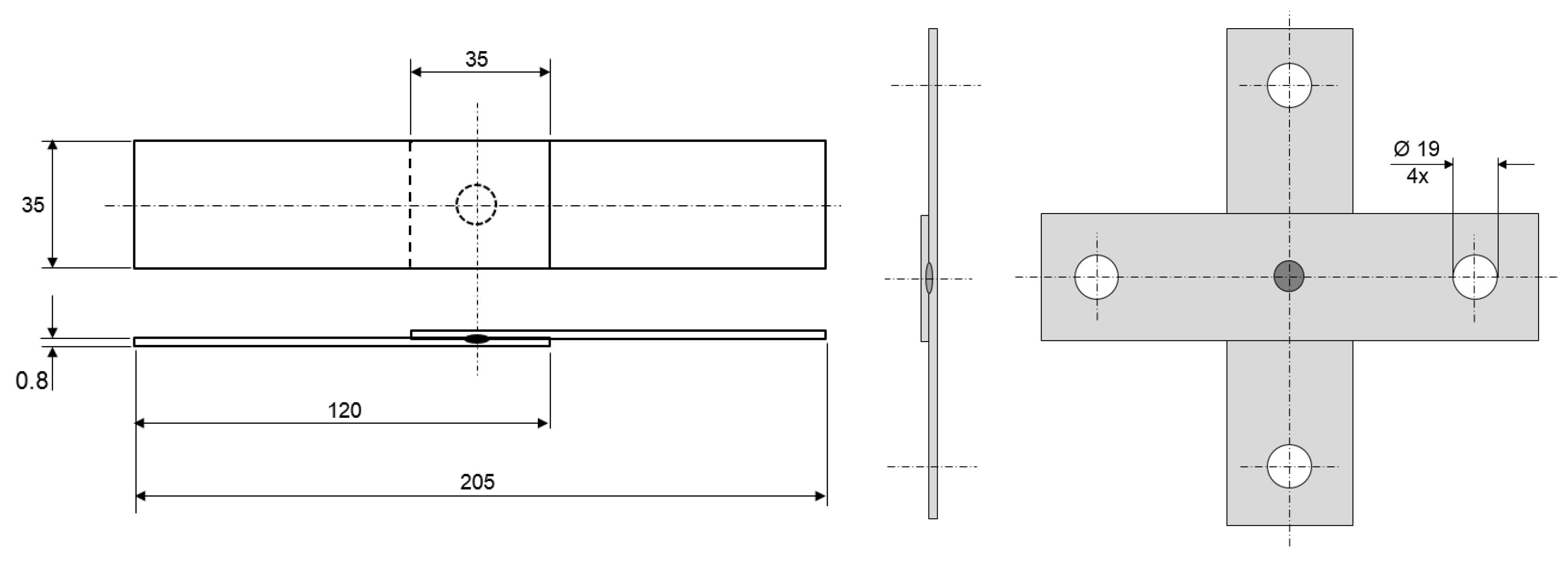
2.1. Characteristics of the Test Speciments

For the accomplishment of the experiments, low carbon steel sheets from the automotive industry with 0.8 mm of thickness and coated with zinc by the process of hot immersion were used. Table 1 presents the main elements concerning the chemical composition of the sheet used in the experiments.
The sheets were overlapped and welded through a spot made in the middle of this area, both for the tensile shear tests and for the cross-tension tests, as shown in Figure 1. In this way, spot welding was performed by resistance using the hump created by additive manufacturing, as well as, by way of comparison, the resistance spot welding process (RSW). The dimensions of the specimens were based on AWS B4.0 standard.
Table 2 shows the mechanical properties of the zinc coated steel sheet used in the experiments.

2.2. Characteristics of the Metallic Powder for the Laser Deposition (Additive Manufacturing) Used in the Experiments

The metal powder used in the experiments, through the process with laser deposition (additive manufacturing), was the austenitic stainless steel 316L manufactured by the gas atomization process. Table 3 shows the chemical composition of the metal powder used in the experiments.

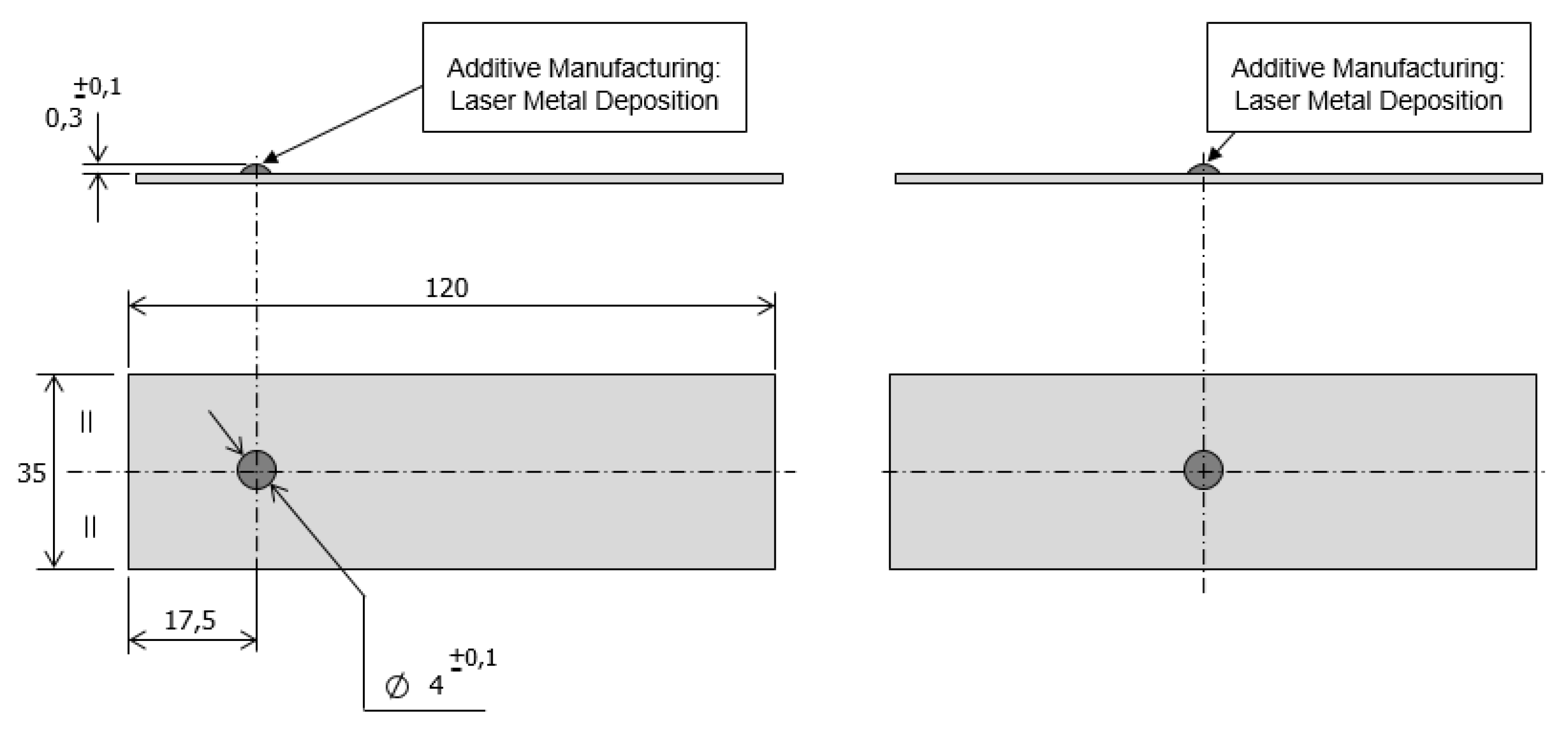
2.3. Additive Manufacturing Process for Laser Powder Deposition Used in Experiments

Resistance spot welding using additive manufacturing (AMWS) was performed in two stages. In the first stage, the deposition or printing of a spherical cap with a predetermined geometry was performed on individual sheets, for the tensile shear test and the cross-tension test, as shown in Figure 2. The chosen geometry for deposition or printing on the sheet was circular, to be later compared with the conventional resistance spot welding process (RWS). The equipment used in the experiments to perform laser deposition with metallic powder was model RPMI 535, manufactured by the company RPM INNOVATIONS, INC (Rapid City, SD USA). This equipment has five axes for the control of the movements, of which three axes for moving the nozzle and two for moving the fixing table.
In the second stage the sheets were overlapped, one sheet with the MA deposition and the other without. Subsequently, the electrodes with flat contact face, were positioned in the sheets at the same coordinates of the deposition for the execution of resistance spot welding, as shown in Figure 3.

2.4. Characteristics of the Resistance Spot Welding Equipment Used in the Experiments

In the experiments, a stationary resistance spot welding equipment was used. This equipment has a servo motor for the system of force and movement between the electrodes, with a maximum capacity of 5.0 kN. The welding current used was one of the medium frequency direct currents.
The contact geometry (electrode/sheet) employed during the experiments, referring to the additive manufacturing spot welding (AMSW), was the flat face. Regarding the resistance spot welding (RSW), a spherical contact face electrode with a radius of 8 mm and a diameter of 16 mm and a height of 20 mm was used.

2.5. Welding Spot Acceptance Criteria

Table 4 shows the minimum dimensions for weld spot diameter approval, as well as the minimum strength for tensile shear tests and cross-tension tests, which are directly related to the thickness of the sheet.

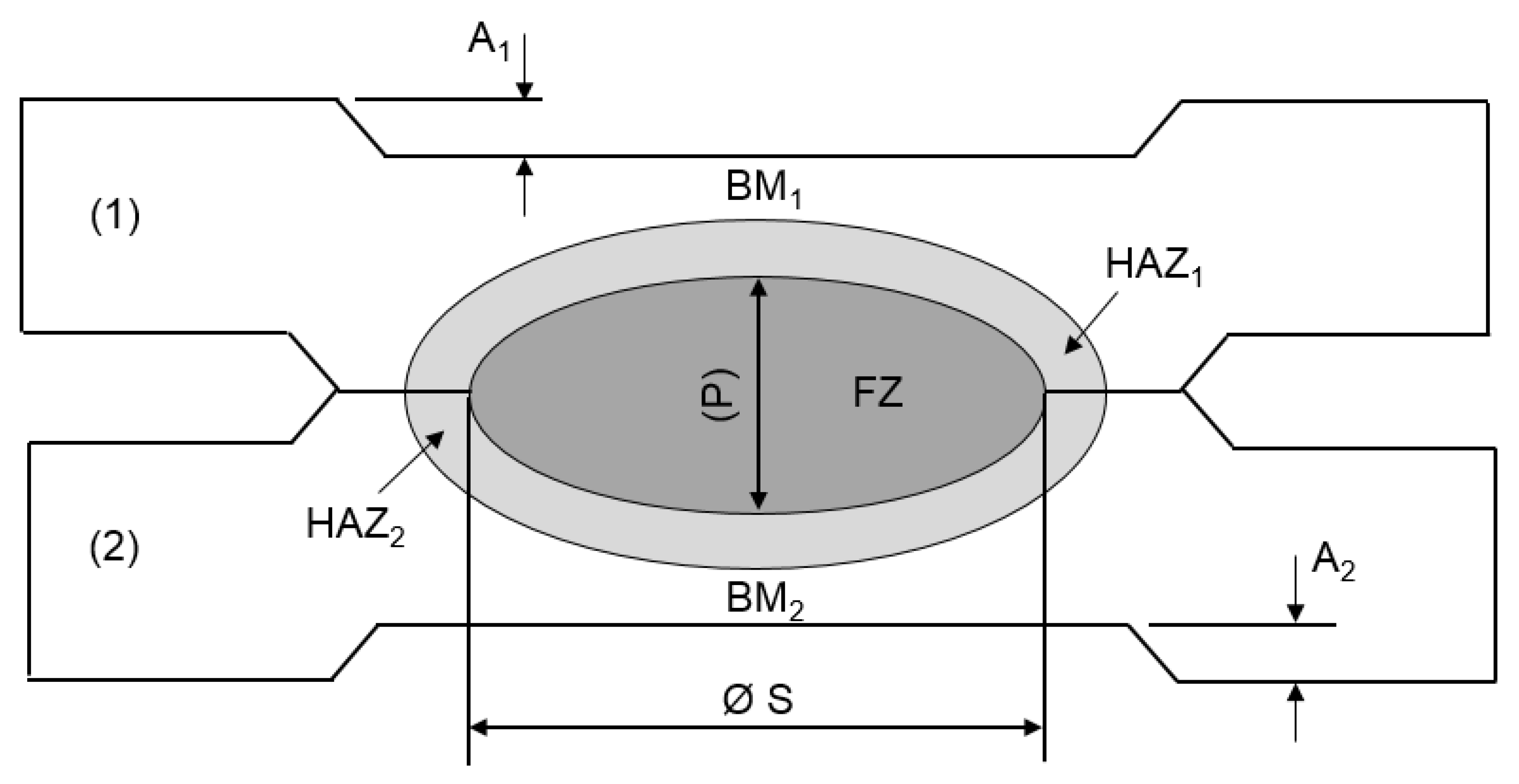
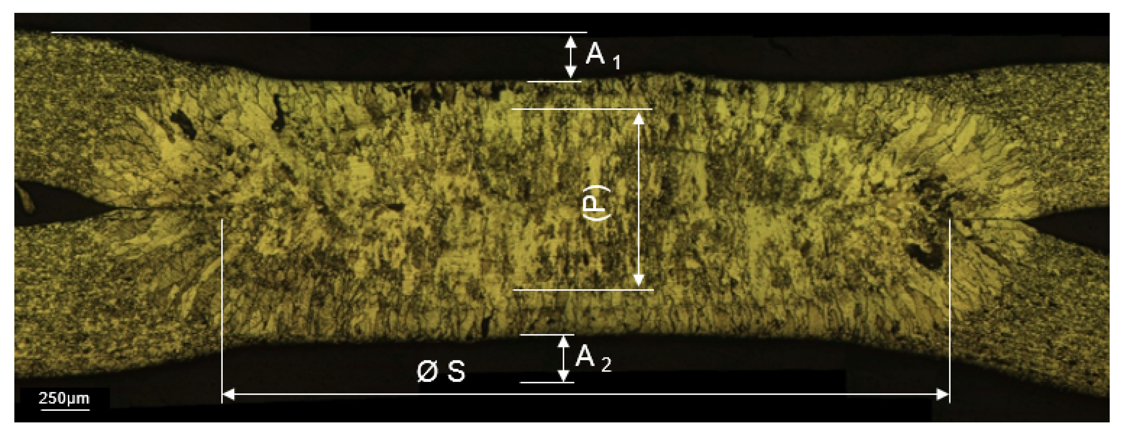
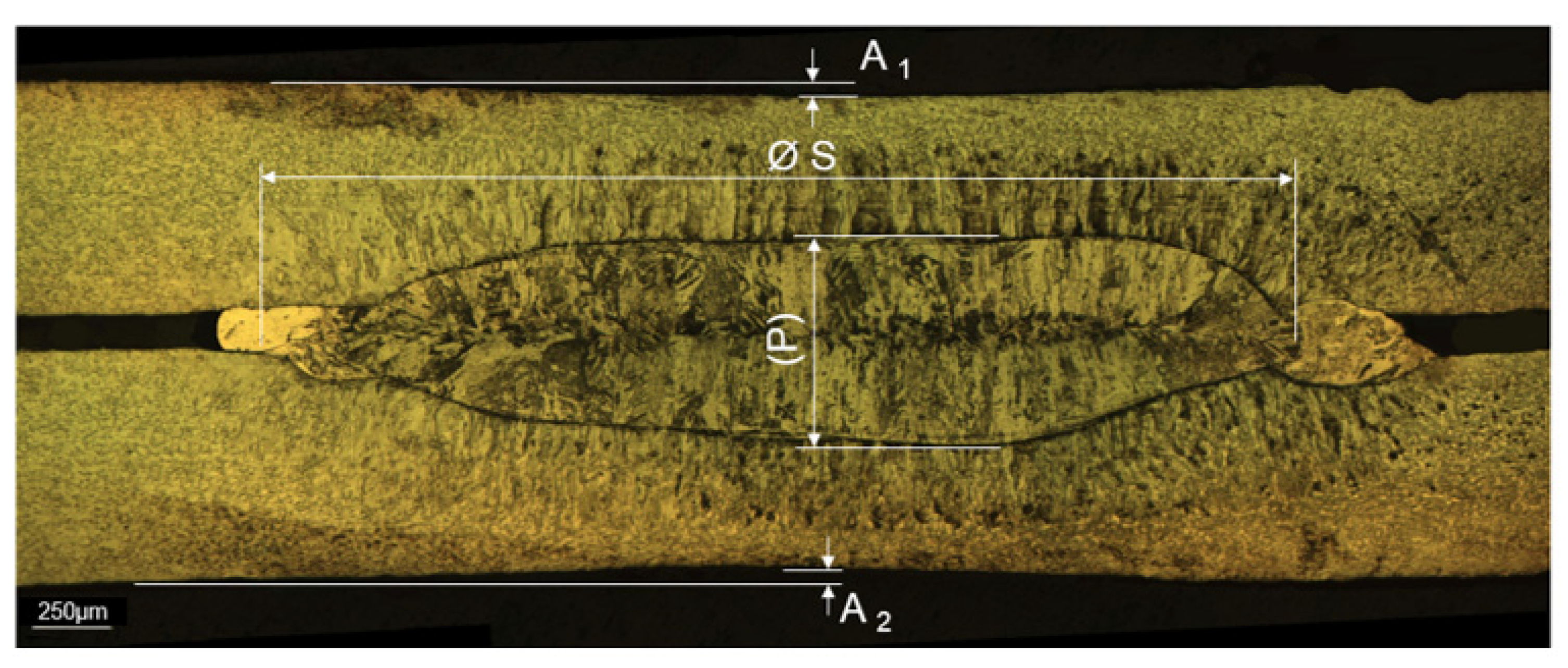
2.6. Characterization of the Spot Welding Joint Geometry

The characterization of spot-welded joint geometry was based on macrography results. Figure 4 presents a schematic representation of a spot-welded joint geometry of sheet (1) and sheet (2). In this figure the identifications represent: (A) the depth of indentation; (BM) the length of the sheet material not affected by heating and cooling; (HAZ) the length of the steel sheet of base metal which was affect by heating and cooling; and FZ is the fusion zone.

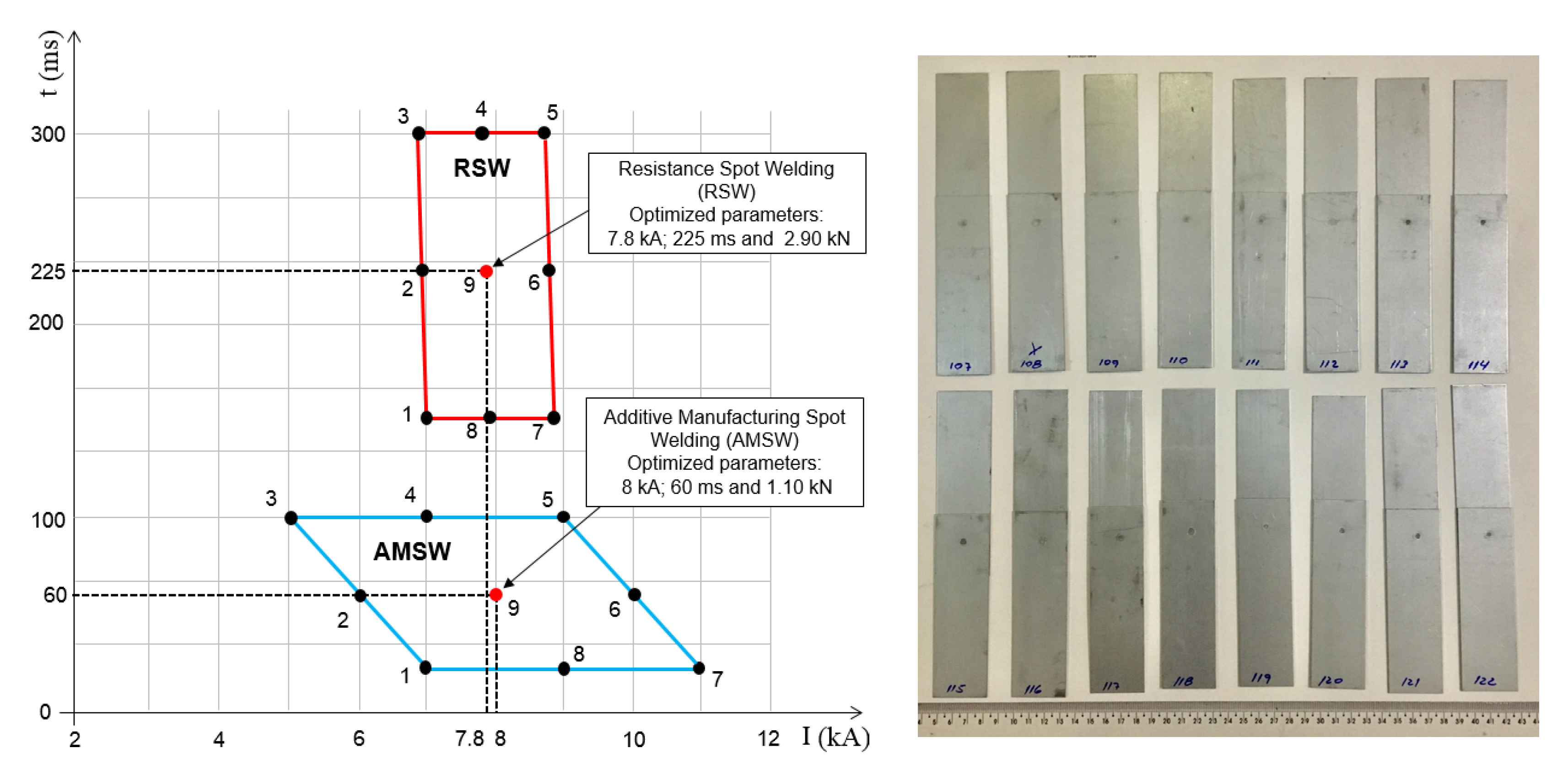
2.7. Determination of Weldability Diagrams and Optimized Welding Parameters

Weldability diagrams were performed for both the resistance spot welding process (RSW) and the spot welding using additive manufacturing (AMSW). The determination of the weldability diagrams was built up locating the optimized welding time and welding current of each process. Afterwards, the optimized parameters were utilized to produce samples for spot weld geometric dimensions (macrographs) and the spot weld mechanical properties (tensile shear tests and cross-tension tests).

3. Results and Discussion

3.1. Weldability Diagrams

After the execution of the weldability diagrams, the optimized welding parameters were determined. These were selected through a spot of greatest degree of freedom, concerning the welding parameters, within the area of the diagram (point 9), as shown in Figure 5.
Analyzing Figure 5, it is possible to observe that in relation to the optimized parameters, the welding time was 275.0% higher for RSW than for AMSW. At the same time, the electrode pressure was 163.6% higher for RSW. This result is due to the higher concentration of thermal energy through the laser addictive manufacturing deposition, as well as the higher electrical resistivity and lower thermal conductivity of the deposited material, when compared to the base material. These facts result in greater efficiency in the generation of thermal energy during welding by Joule heating. On the other hand, the welding current in the resistance spot welding process was lower by 2.5% in relation to the parameters optimized by the spot welding process using additive manufacturing.

3.2. Dimensions of the Weld Spots through the Macrography Tests

Through the macrography tests, the dimensions of the weld spots were determined, using the optimized parameters, referring to the spot welding process using additive manufacturing (AMSW), as well as, for the resistance spot welding process (RSW), as shown Figure 6 and Figure 7.
By the analysis of Figure 7, it is possible to observe that, in general, the dilution between the deposited metal and the base material was almost 100% through the optimized parameters, referring to the spot welding process using additive manufacturing. Table 5 presents a comparison between the dimensions of the weld spots in relation to the resistance spot welding process (RSW) and the spot welding process using additive manufacturing (AMSW), through the macrography tests. All results presented are an average of three measurements.
As shown in Table 5, the indentation (A1 and A2) were, on average, five times lower for the spot-welding process using additive manufacturing (AMSW). This small depression was imperceptible to the visual inspection, giving a spot welding performed by resistance using additive manufacturing a very good aesthetic finishing. The indentation depth for AMSW is related to many factors, one of them is the heat generated by Joule effect in the faying surfaces. The contact resistance at the faying surface is important to obtain a spot weld with quality. The energy generated is proportional to the total electrical resistance of the joint and by the welding current to melt sheets, and produce the nugget. The faying surfaces contact resistances play an important role in producing the weld nugget by Joule heating effect [21]. In the case of the AMSW one face is carbon steel and the other is AISI 316L laser deposited by additive manufacturing (AM), which introduces two different materials, with distinct electrical contact resistances. Figure 8 depicts the contact resistance at room temperature for AISI 316L, HSLA galvanized, and SAE 1008 with and without galvanized coating. In the same figure is shown the contact resistance for AISI 316L at 700 °C [22].
Analyzing this picture, in the pressure range between 50 and 100 MPa, the contact resistance for AISI 316L at room temperature is close to one order of magnitude higher than SAE 1008 (g) and SAE 1008 (w/g). This means the Joule heating is much higher for AMSW, than for RSW, explaining the lower welding time presented by AMSW, depicted in Figure 5. In addition, because of a reduced welding time for AMSW, a partial burning of the zinc coating on the sheet steel surface occurs, as shown in Figure 9, which helps in the corrosion resistance in the welded region by AMSW process.

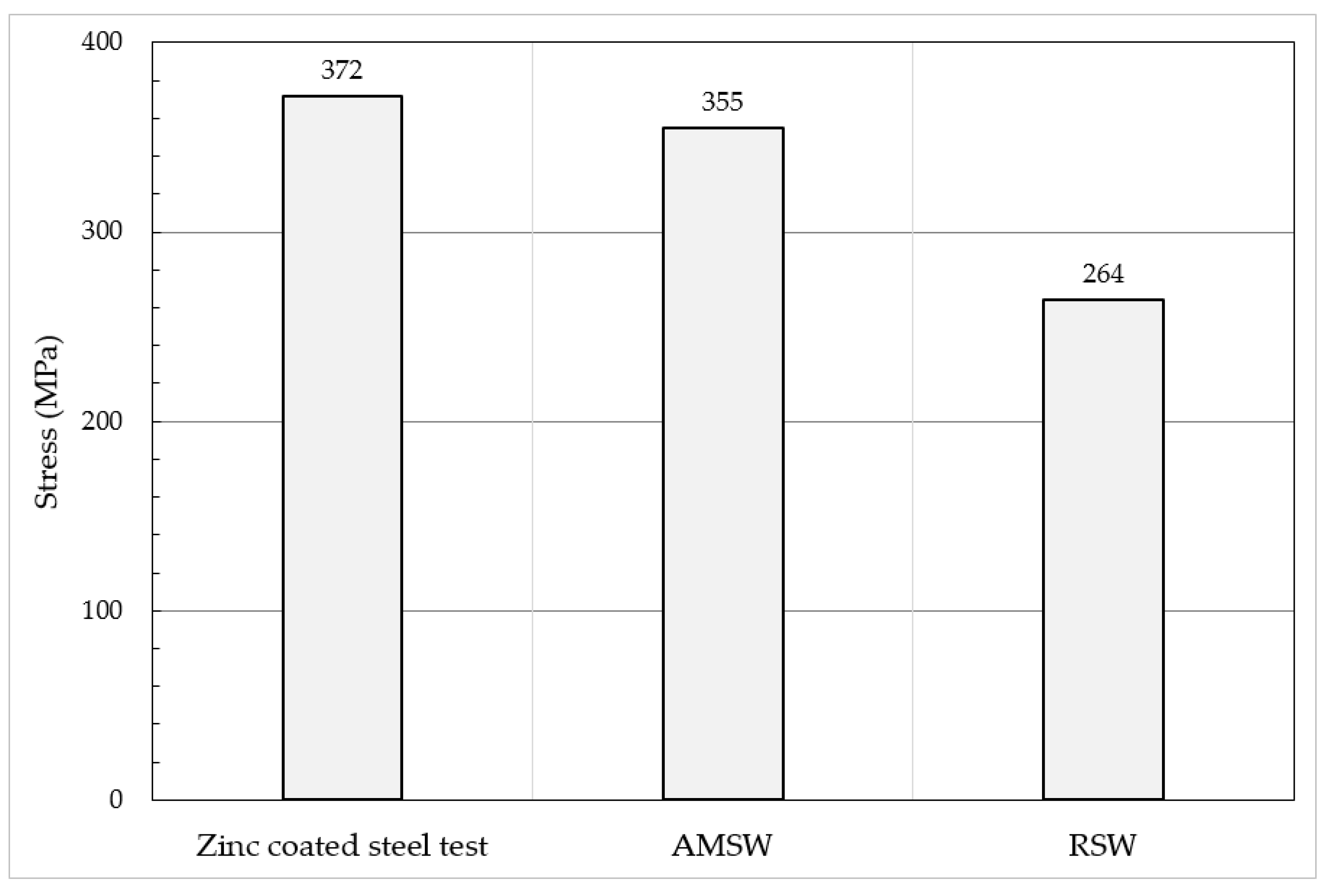
3.3. Maximum Tensile Shear Stress

Table 6 presents the results (average of 3 samples) of the maximum tensile stress by shearing of the weld spots, through the optimized welding parameters, by additive manufacturing (AMSW) spot welding, as well as, by the resistance spot-welding process (RSW), comparing the two welded joints with the maximum tensile stress of the sheet. In order to obtain greater accuracy in the stress calculations, the diameters of the weld spots found in the macrography tests were used.
Figure 10 presents the results of Table 6 through the bar graph, in order to facilitate the analysis of the differences between the maximum tensile shear stress of the weld spots in relation to the maximum stress of the zinc coated sheet.
By the analysis of Figure 10, it is possible to notice that the maximum tensile shear stress related to the spot welding process using additive manufacturing (AMSW) presented itself 4.57% lower if compared to the maximum tensile stress of the zinc coated sheet zinc. However, the maximum tensile stress by shear through the resistance spot welding process (RSW), was lower by 29.1%, when compared to the maximum tensile stress of the coated sheet of zinc. It is also noticed that the maximum tensile stress by shearing through the process of spot welding using additive manufacturing (AMSW) was 34.47% higher in relation to the process of resistance spot welding (RSW). This result is related to the lower HAZ (heat-affected zone), the absence of indentation and also the higher mechanical resistance of the alloy deposited in relation to the base material, referring to the spot welding process using additive manufacturing (AMSW).

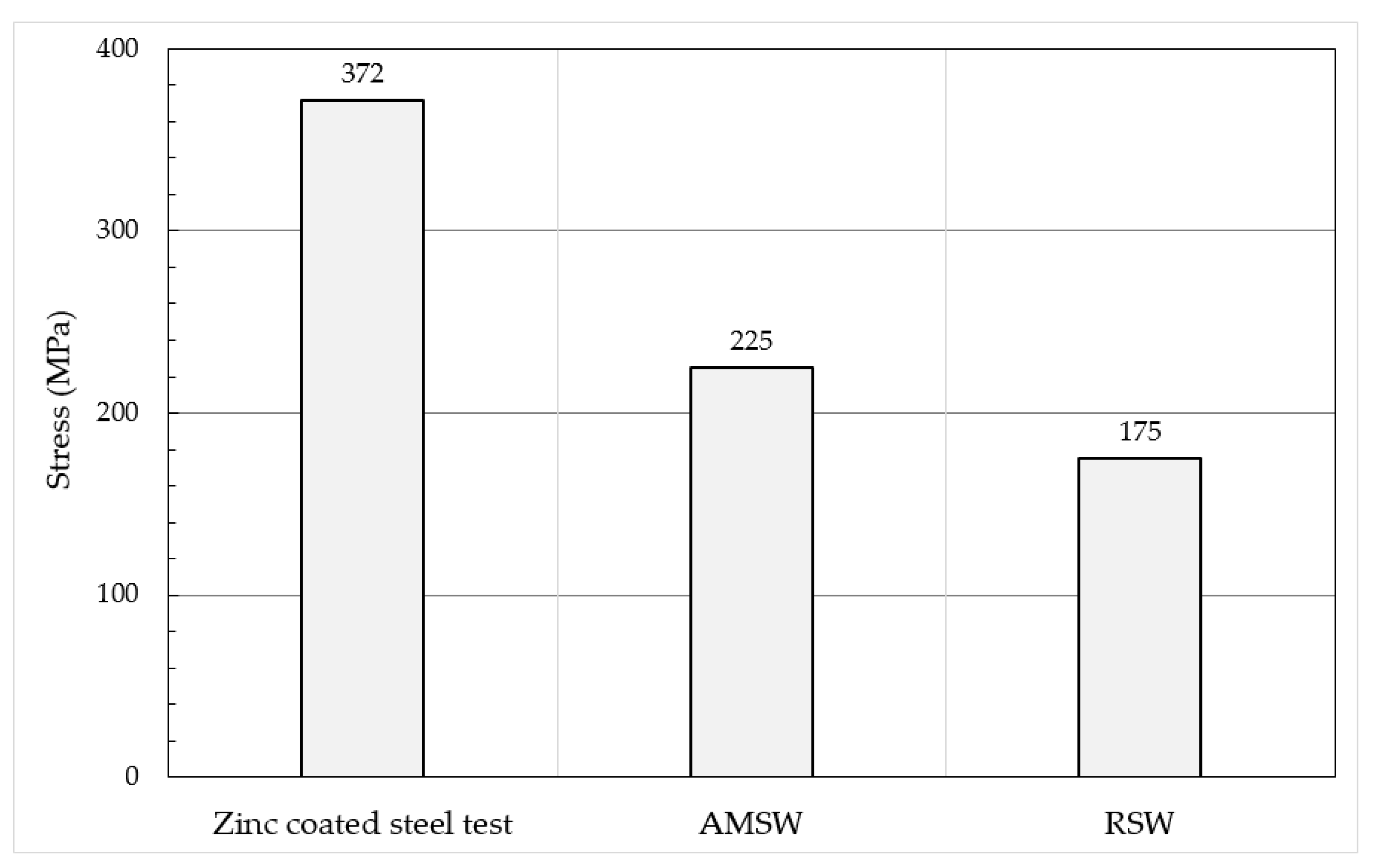
3.4. Maximum Tensile Stress for Cross-Tension Test

Table 7 presents the results (average of three samples) of the maximum tensile stresses of the cross- tension test with perpendicular load to the weld spot, through the optimized parameters, by the spot- welding process using additive manufacturing (AMSW), as well as by the resistance spot welding process (RSW), comparing the two processes with the maximum tensile stress of the sheet. In order to obtain greater accuracy in the stress calculations, the diameters of the weld spots found in the macrography tests were utilized to calculate the maximum tensile stresses.
Figure 11 shows the results from Table 7 through the bar graph in order to facilitate the analysis of the differences between the maximum tensile stresses with perpendicular load to the weld spot with cross- tension, in relation to the maximum sheet tension.
By the analysis of Figure 11, it is possible to observe that the stress related to the tensile shear tests (item 3.3), were 57.78% and 50.86% higher in relation to the spot welding process using additive manufacturing (AMSW), and also for the resistance spot welding process (RSW), respectively, when compared to the results of the cross-tension tests. This result is related to the lower deformation rates for the tensile shear test.
Also, by the analysis of Figure 11, it is possible to observe that the maximum tensile strength of the weld spot in a cross-tension test, referring to the spot welding process using additive manufacturing (AMSW), was 39.52% lower compared to the maximum tension of the sheet. However, the maximum tensile strength of the weld spot in a cross-tension test by the resistance spot welding process (RSW) was lower by 52.96%, compared to the stress of the zinc coated sheets. It can also be observed that the maximum tensile stresses with cross-tension test, by the process of spot welding using additive manufacturing (AMSW), was higher in 28.57%, compared to the process of resistance welding spot (RSW). Similar to the previously analyzed results (item 3.3—tensile shear stress), these results are related to the lower HAZ (heat-affected zone), the absence of indentation and also the higher mechanical resistance of the deposited alloy in relation to the base material, referring to the spot welding process using additive manufacturing (AMSW).

4. Conclusions

Based on the materials used, the experiments performed and the results obtained, it is possible to conclude that:
  • In general, the dilution between the deposited metal and the base material was total, using the optimized parameters, in zinc coated sheets, it can be concluded that this new process of spot welding using additive manufacturing (AMWS) is by melting and pressing.
  • The welding time for the optimized parameters, by the resistance spot welding process (RSW), was higher by 275% when compared to the time of the optimized parameters of the spot welding process using additive manufacturing (AMSW). This result is related to the higher concentration of thermal energy in a predetermined area, performed through the laser deposition, as well as, with the higher electrical resistivity, and lower thermal conductivity of the deposited material compared to the base material. Therefore, one can conclude that these facts result in lower losses and greater efficiency in the generation of thermal energy, when compared to the resistance spot welding process (RWS).
  • The strength between the electrodes in relation to the optimized parameters, by the resistance welding process (RSW), was higher by 163.6%, compared to the strength of the optimized parameters of the spot welding process using additive manufacturing (AMSW), it can be concluded that this new process of spot welding requires smaller equipment, and consequently lower costs.
  • The maximum stress of the weld spot in relation to the tensile shear tests and the cross-tension tests, referring to the spot welding process using additive manufacturing (AMSW), was 34.47% and 28.57% higher respectively, in comparison to the resistance spot welding process (RSW). These results are related to the lower HAZ (heat-affected zone), the absence of indentation and also the greater mechanical resistance of the alloy deposited in relation to the base material. It can be concluded that this new process of spot welding using additive manufacturing, under optimized conditions, has higher mechanical resistance in static shear stresses and static stresses perpendicular to the weld spot compared to the resistance spot welding process (RSW).
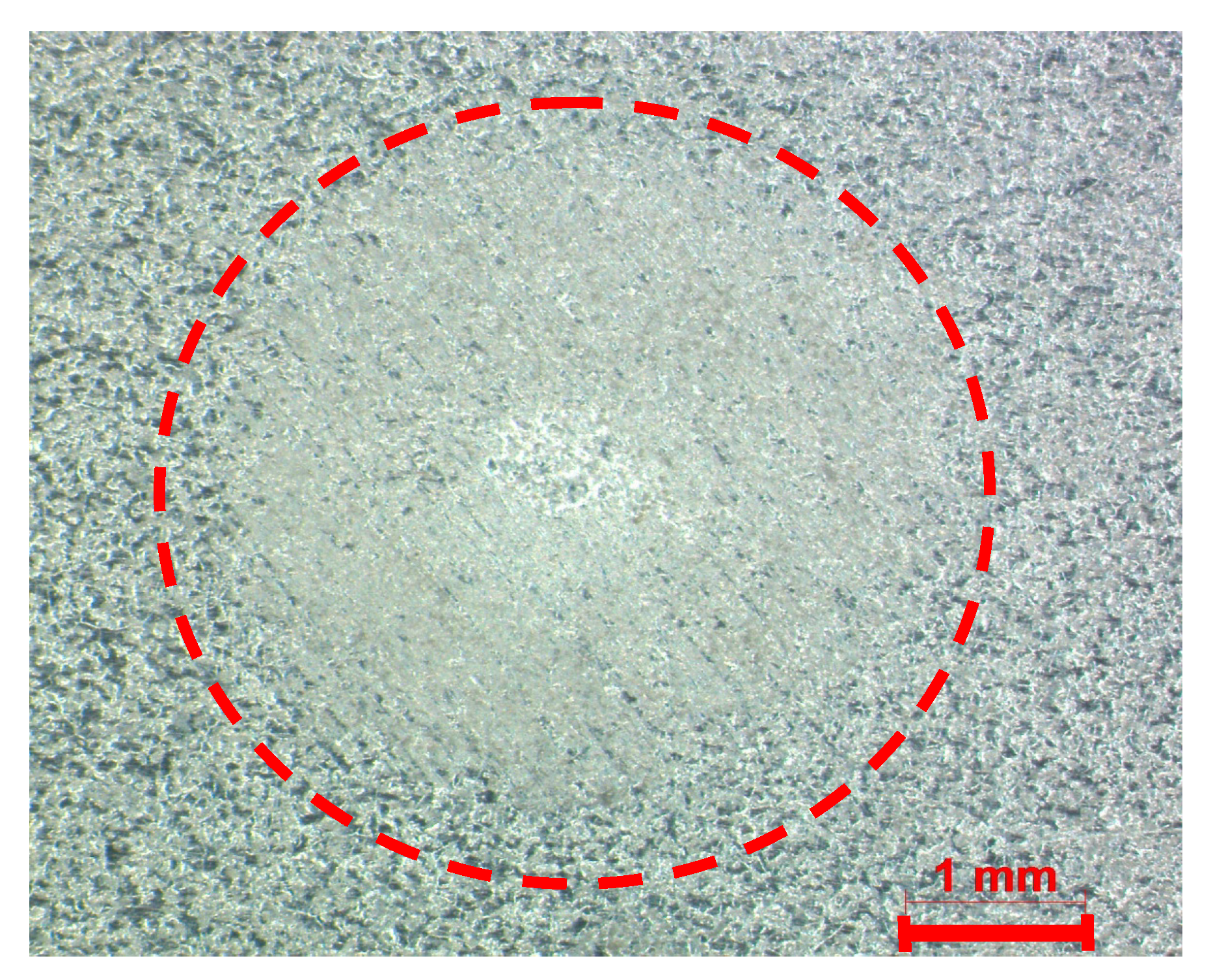
  • The indentation or thermomechanical mark on the surface of the sheet, referring to the spot welding process using additive manufacturing (AMSW), through the optimized parameters, were imperceptible to the visual inspection. It can be concluded that this new welding process, in relation to aesthetics, can be used on apparent surface.

5. Patent

The process of resistance spot welding using additive manufacturing (AMSW) was patented by the authors of this article. Patent Number: US 15442655 – USA.

Author Contributions

M.B., V.F., and S.D.B. conceived and designed the experiments; M.B. and V.F. performed the experiments; M.B. and S.D.B. analyzed the data; and M.B. and S.D.B. wrote the paper. All authors have read and agree to the published version of the manuscript.

Funding

This research received no external funding.

Conflicts of Interest

The authors declare no conflict of interest.

References

  1. Pouranvari, M. Susceptibility to interfacial failure mode in similar and dissimilar resistance spot welds of DP600 dual phase steel and low carbon steel during cross-tension and tensile-shear loading conditions. Mater. Sci. Eng. A 2012, 546, 129–138. [Google Scholar] [CrossRef]
  2. Martín, O.; Ahedo, V.; Santos, J.I.; Tiedra, P.; Galán, J.M. Quality assessment of resistance spot welding joints of AISI 304 stainless steel based on elastic nets. Mater. Sci. Eng. A 2016, 676, 173–181. [Google Scholar] [CrossRef] [Green Version]
  3. Anijdana, S.H.M.; Sabzib, M.; Hasabc, G.M.; Ghiyas, R.A. Optimization of spot welding process parameters in dissimilar joint of dual phase steel DP600 and AISI 304 stainless steel to achieve the highest level of shear-tensile strength. Mater. Sci. Eng. A 2018, 726, 120–125. [Google Scholar] [CrossRef]
  4. Marashi, P.; Pouranvari, M.; Amirabdollahian, S.; Abedi, A.; Goodarzi, M. Microstructure and failure behavior of dissimilar resistance spot welds between low carbon galvanized and austenitic stainless steels. Mater. Sci. Eng. A 2008, 480, 175–180. [Google Scholar] [CrossRef]
  5. Brauser, S.; Pepke, L.A.; Weber, G.; Rethmeier, M. Deformation behaviour of spot-welded high strength steels for automotive applications. Mater. Sci. Eng. A 2010, 527, 7099–7108. [Google Scholar] [CrossRef]
  6. Babu, N.K.; Brauser, S.; Rethmeier, M.; Cross, C.E. Characterization of microstructure and deformation behaviour of resistance spot welded AZ31 magnesium alloy. Mater. Sci. Eng. A 2012, 549, 149–156. [Google Scholar] [CrossRef]
  7. Ramazani, A.; Mukherjee, K.; Abdurakhmanov, A.; Abbasi, M.; Prahl, U. Characterization of Microstructure and Mechanical Properties of Resistance Spot Welded DP600 Steel. Metals 2015, 5, 1704–1716. [Google Scholar] [CrossRef] [Green Version]
  8. Pouranvari, M. Fracture toughness of martensitic stainless steel resistance spot welds. Mater. Sci. Eng. A 2017, 680, 97–107. [Google Scholar] [CrossRef]
  9. Huin, T.; Dancette, S.; Fabrègue, D.; Dupuy, T. Investigation of the Failure of Advanced High Strength Steels Heterogeneous Spot Welds. Metals 2016, 6, 111. [Google Scholar] [CrossRef]
  10. Emre, H.E.; Kaçar, R. Resistance Spot Weldability of Galvanize Coated and Uncoated TRIP Steels. Metals 2016, 6, 299. [Google Scholar] [CrossRef] [Green Version]
  11. Fukumoto, S.; Fujiwara, K.; Toji, S.; Yamamoto, A. Small-scale resistance spot welding of austenitic stainless steels. Mater. Sci. Eng. A 2008, 492, 243–249. [Google Scholar] [CrossRef]
  12. Han, J.H.; Shan, P.; Hu, S.S. Contact analysis of fractal surfaces in earlier stage of resistance spot welding. Mater. Sci. Eng. A 2006, 436, 204–211. [Google Scholar] [CrossRef]
  13. Pouranvari, M.; Marashi, S.P.H.; Safanama, D.S. Failure mode transition in AHSS resistance spot welds. Part II: Experimental investigation and model validation. Mater. Sci. Eng. A 2011, 528, 8344–8352. [Google Scholar] [CrossRef]
  14. Pouranvari, M.; Marashi, S.P.H. Failure mode transition in AHSS resistance spot welds. Part I. Controlling factors. Mater. Sci. Eng. A 2011, 528, 8337–8343. [Google Scholar] [CrossRef]
  15. Spena, P.R.; Maddis, M.; D’Antonio, G.; Lombardi, F. Weldability and Monitoring of Resistance Spot Welding of Q&P and TRIP Steels. Metals 2016, 6, 270. [Google Scholar]
  16. Tutar, M.; Aydin, H.; Bayram, A. Effect of Weld Current on the Microstructure and Mechanical Properties of a Resistance Spot-Welded TWIP Steel Sheet. Metals 2017, 7, 519. [Google Scholar] [CrossRef] [Green Version]
  17. Arrizubieta, J.I.; Ruiz, J.E.; Martinez, S.; Ukar, E.; Lamikiz, A. Intelligent nozzle design for the Laser Metal Deposition process in Industry 4.0. ScienceDirect–Procedia Manuf. 2017, 13, 1237–1244. [Google Scholar] [CrossRef]
  18. Tabernero, I.; Lamikiz, A.; Ukar, E.; Lacalle, L.N.; Angulo, C.; Urbikain, G. Numerical simulation and experimental validation of powder flux distribution in coaxial laser cladding. Mater. Process. Technol. 2010, 210, 2125–2134. [Google Scholar] [CrossRef]
  19. Frazier, W.E. Metal Additive Manufacturing: A Review. Mater. Eng. Perform. 2014, 23, 1917–1928. [Google Scholar] [CrossRef]
  20. Junker, D.; Hentschel, O.; Schmidt, M.; Merklein, M. Investigation of Heat Treatment Strategies for Additively-Manufactured Tools of X37CrMoV5-1. Metals 2018, 8, 854. [Google Scholar] [CrossRef] [Green Version]
  21. Batista, M.; Brandi, S.D. Use of dynamic resistance and dynamic energy to compare two resistance spot welding equipments for automotive industry in zinc coated and uncoated sheets. Am. J. Eng. Res. 2013, 2, 79–93. [Google Scholar]
  22. Nielsen, C.V.; Zhang, W.; Alves, L.M.; Bay, N.; Martins, P. Modeling of Thermo-Electro-Mechanical Manufacturing Processes; Springer: London, UK, 2013; 120p. [Google Scholar]
Figure 1. Schematic drawing of the test specimens used in the experiments, both for tensile shear tests and cross-tension test, respectively, dimensions based on AWS B4.0 standard.
Metals 10 00555 g001
Figure 2. Schematic drawing of the specimens for the execution of the laser deposition (additive manufacturing) using metal powder, for both tensile tests and cross-tension tests, respectively.
Metals 10 00555 g002
Figure 3. Schematic drawing of spot welding using additive manufacturing.
Metals 10 00555 g003
Figure 4. Schematic drawing of a spot welding joint geometry.
Metals 10 00555 g004
Figure 5. Weldability diagram for the determination of the optimized parameters, both for the spot welding process using additive manufacturing (AMSW) and for the resistance spot welding process (RSW), as well as examples of test specimens used in the experiments, respectively.
Metals 10 00555 g005
Figure 6. Example of macrography in relation to the resistance spot welding process (RSW).
Metals 10 00555 g006
Figure 7. Example of macrography in relation to the spot welding process using additive manufacturing (AMSW).
Metals 10 00555 g007
Figure 8. Contact resistance for AISI 316L; HSLA galvanized (g); SAE 1008 without zinc coating (w/g) and SAE 1008 galvanized and AISI 316L at 700 °C. Adapted from [22].
Metals 10 00555 g008
Figure 9. Image of zinc coated sheet surface after spot welding using additive manufacturing (AMSW).
Metals 10 00555 g009
Figure 10. Comparison of maximum tensile shear stress between the weld spots by the spot welding process using additive manufacturing (AMSW) and the resistance spot welding process (RSW), in relation to the maximum tensile stress of the zinc coated sheet.
Metals 10 00555 g010
Figure 11. Comparison of maximum tensile stresses of weld points under cross-tension test, between spot welding process using additive manufacturing (AMSW) and the resistance spot welding process (RSW), in relation to the maximum tension of the zinc coated sheet.
Metals 10 00555 g011
Table 1. Chemical composition of the steel sheets used in the experiments.
AlloyCMnPSSiCuNiCrMoAlTi
wt %0.00300.61000.03300.00460.07700.01800.00560.02300.00200.05000.0480
Table 2. Mechanical properties of the zinc coated steel sheet.
Mechanical PropertiesValues
Yield Strength [MPa]188
Tensile Strength [MPa] 372
Ductility [% Elongation]44
Table 3. Chemical composition of the metallic powder - Stainless Steel 316L.
AlloyCMoNiMnCrSiFe
wt %0.0152.613.11.617.20.7Balance
Table 4. Dimensions and minimum tensile strength used for welding spot approval.
Sheet Thickness
(mm)
Spot Diameter
(Macrography Test)
(mm)
Spot Diameter
(Peel Test)
(mm)
Min. Strength:
Tensile Shear Test
(kN)
Min. Strength:
Cross-Tension Tests (kN)
0.83.13.62.301.38
Table 5. Dimensions of the spot-welded joints by the macrography tests (mm).
Welding ProcessSpot Diameter Indentation Base Metal HAZ Extension Spot Thickness
Ø SA1A2BM1BM2HAZ1HAZ2(P)
RSW4.920.250.200.00.00.830.680.82
AMSW3.600.050.070.230.180.170.330.71
Table 6. Maximum tensile shear stress of the weld spots and the sheet (average of three samples).
Welding ProcessØ S
Spot Diameter
(mm)
Max.Tensile
Shear Load
(kN)
Max. Tensile
Shear Stresses
of the Weld Spot
(MPa)
Max. Tensile
Stress
of the Sheet
(MPa)
RSW4.925.012264372
AMSW3.603.613355372
Table 7. Maximum tensile stress for cross-tension test of the weld spots and the sheet (average of three samples).
Welding ProcessØ S
Spot Diameter
(mm)
Max.Tensile
Shear Load
(kN)
Max. Tensile
Stresses
of the Spot
(MPa)
Max. Tensile
Stress
of the Sheet
(MPa)
RSW4.92 3.32175372
AMSW3.602.29225372

