Article

Microstructural Evolution and Growth of Intermetallic Compounds at the Interface between Solid Cast Iron and Liquid Al–Si Alloy

1
Department of Advanced Materials Engineering, Hanbat Natinal University, 125 Dongseo-daero, Yuseong-gu, Daejeon 34158, Korea
2
School of Materials Science and Engineering, Changwon National University, 20 Changwondaehak-ro, Uichang-gu, Changwon, Gyeongsangnam-do 51140, Korea
3
Research Institute of Advanced Manufacturing Technology, Korea Institute of Industrial Technology, 156 Getbbeol-ro, Yeonsu-gu, Incheon 21999, Korea
*
Author to whom correspondence should be addressed.
Metals 2020, 10(6), 759; https://doi.org/10.3390/met10060759
Submission received: 17 April 2020 / Revised: 25 May 2020 / Accepted: 2 June 2020 / Published: 6 June 2020
(This article belongs to the Special Issue Formation of Intermetallic Phases in Solidifying Al-Fe-Si Melts)

Abstract

:
Compound casting has received a great deal of attention as a useful method for fabricating a single complicated part from dissimilar metallic materials. For example, in the case of automobile cylinder blocks, research is being carried out to compound cast iron with aluminum alloys. In order to manufacture such as composite parts, it is essential to control the intermetallic compound formed at the interface between two metals. In this research, the type and growth behavior of compounds formed at the interface between cast iron and aluminum, or Al–Si alloy, were investigated. It was observed that the Al5Fe2 phase was mainly formed at the interface between the pure aluminum melt and the solid cast iron, and the thickness of the interfacial compound increased proportionally with increasing contact time. On the other hand, more complex phases were formed at the interface between the Al–Si alloy melt and the solid cast iron. In the case of a specimen having a contact time of 10 min, Al4.5FeSi, Al8Fe2Si and Al5Fe2 phases appeared to occupy the largest portion of the interfacial compound region. The total thickness of the interfacial compounds also increased in proportion to the contact time.

1. Introduction

As the demand for weight reduction continues to increase, especially in the automotive industry, efforts to replace previous iron-based parts using aluminum alloys are also on the rise. However, aluminum alloys have lower mechanical properties and heat resistance than iron-based alloys, in spite of their many advantages. Because the relatively low properties of aluminum alloys are limiting their expansion, much attention has been focused on a technique for manufacturing an iron-based alloy, and an aluminum alloy as a composite part, in order to overcome the low properties of the aluminum alloy. There are various methods of manufacturing composite parts, but among them, the compound casting method, which is capable of manufacturing a complicated shape part, and has excellent economical merit, has received a great deal of attention [1,2,3].
In the case of the cast joining of an iron-based alloy and aluminum alloy, a reaction occurs between a solid iron and a liquid Al alloy. First, the iron may be partly dissolved in an aluminum alloy melt, depending on the process conditions [4,5,6]. It is also expected that various intermetallic compounds will form and grow between Fe/Al interfaces [1,2,3,7,8,9,10,11,12,13,14,15,16,17]. It is known that the Al5Fe2 and Al3Fe phases are mainly formed at the interface between the steel and the pure aluminum melt [7,12,13,14,15,16,17], while various AlFeSi phases, such as Al8Fe2Si and Al4.5FeSi, are known to be mainly formed at the interface between the steel and the Al–Si alloy melt [10,11,16].
Thus far, a lot of investigation has been conducted on the interfacial compounds formed between the steel and the molten aluminum or aluminum alloy. However, in the case of a cast iron/aluminum melt, since cast iron has a different composition and microstructure from steel, it may be different in the types of interfacial compounds.
In order to obtain sufficient bonding between dissimilar metallic materials to occur, it is necessary to form a compound at an interface, but when a large amount of compound is formed, deterioration in its ductility and an interference with heat transfer may occur. The formation conditions of such interfacial compounds are expected to change depending on the composition of Fe-based alloys and aluminum alloys, but the results of research on cast iron with Al–Si alloy, which is widely applied industrially, are insufficient.
This study was conducted as basic research for the development of the compound casting technology of cast iron and Al–Si alloy, which is widely used in the automotive industry. In addition, the main focus was to investigate the types and growth behaviors of the intermetallic compounds formed at the interface.

2. Materials and Methods

As shown in Figure 1, the cast iron insert (diameter of 5 mm, height of 10 mm, cylindrical shaped) was placed in the graphite mold with a diameter of 35 mm. Pure aluminum (99.9 wt.%, NeoDM, Daejeon, Korea) and commercial A356 alloy ingots were heated in a graphite crucible at a high frequency induction furnace, and then prepared molten metal of 720 °C was poured into the graphite mold. The mold was maintained at a temperature of 720 °C for a given time in a furnace, and then was naturally cooled in air. The chemical compositions of the cast iron and the A356 alloy are shown in Table 1. The observation and thickness measurement of the compounds of the cast iron/aluminum interfaces of the specimens were carried out using an optical microscope (OM) and a scanning electron microscope (FE-SEM, SU5000, Hitachi, Tokyo, Japan), equipped with energy dispersive X-ray spectrometer (EDS, JEOL, Tokyo, Japan). The metallographic specimens were polished and then etched using a 0.5% hydrofluoric acid solution in water. Backscatter diffraction (EBSD, TSL Hikari Super Program, EDAX, Mahwah, NJ, USA) analysis was also carried out to investigate the intermetallic compounds at the interface.

3. Results and Discussion

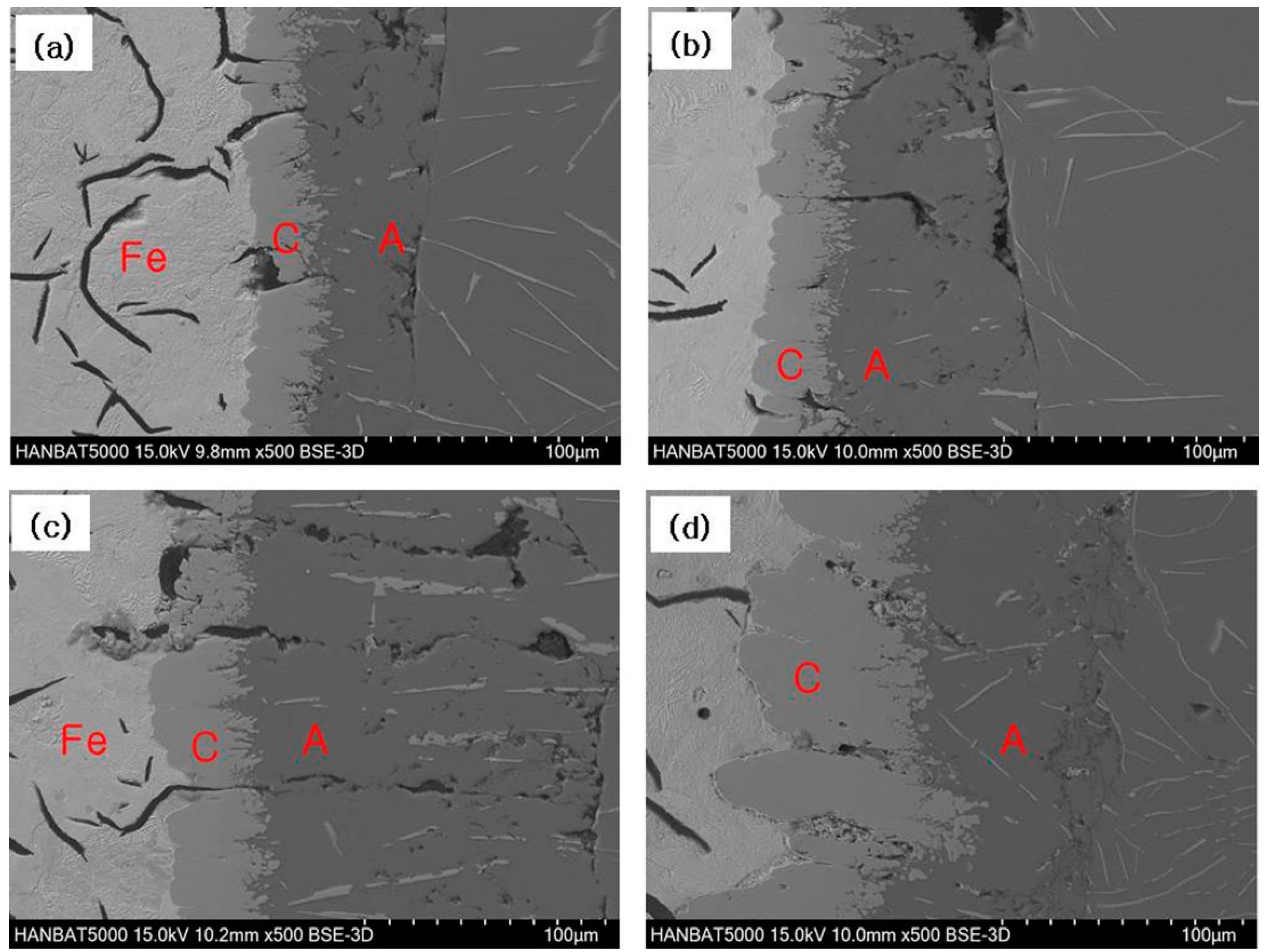
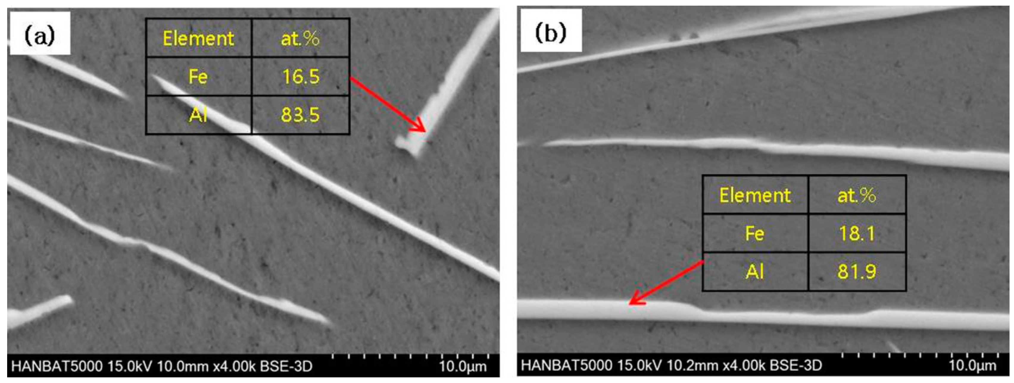
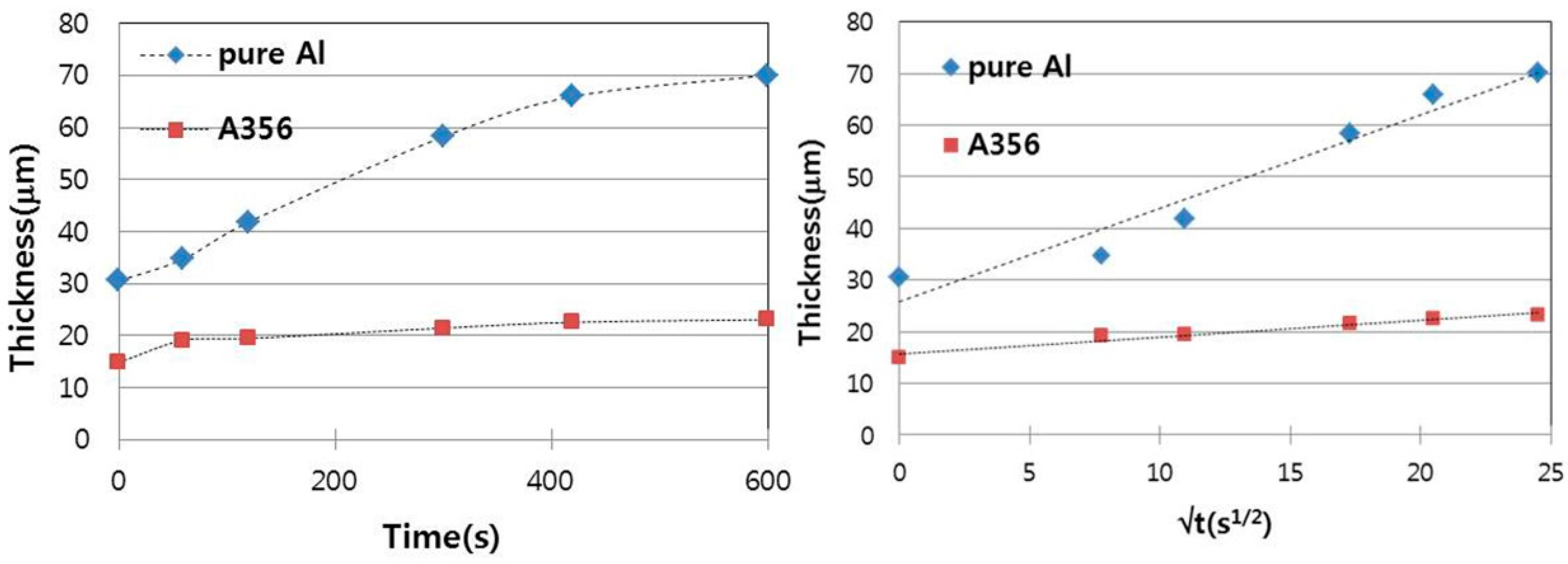
3.1. Cast Iron/Pure Aluminum Interface

Figure 2 shows SEM micrographs of the interface between the cast iron insert and pure aluminum melt formed during isothermal heating with different holding time. Apparently, an AlFe compound was formed at the interface, and its thickness was increased with increased holding time. It is noteworthy that even when the holding time was 0 min, an interfacial compound with significant thickness (about 30 μm) was formed. This is partly due to the fact that the cooling rate of the aluminum melt was not fast, because the melt was poured into the crucible preheated to 720 °C. Although the EDS analysis is not quantitatively accurate, it seems reasonable to judge that it is one of the two AlFe compounds, Al5Fe2 and Al3Fe, from the analysis results in Table 2. According to the literature [1,7,15,16], most interfacial compounds are likely to be of the Al5Fe2 phase.
It is also interesting to note that the iron dissolution occurred clearly from the cast iron insert, and the iron content in the aluminum matrix near the interface was observed to increase even when the hold time was short (Table 2). In Figure 2 and Figure 3, it is also observed that the needle-shaped phases are formed at the aluminum matrix slightly away from the interface. A closer observation of the AlFe compounds was made, as shown in Figure 4. Although more detailed investigation is required, the iron fraction of the AlFe phase tended to be a little increased as the holding time increased. These needle-shaped compounds have been reported to form during the cooling of the aluminum melt with high Fe content, and the phase is believed to be Al3Fe [7].
The thickness of the compound formed and grown at the solid iron and liquid aluminum interface depends upon the diffusion rate of the elements and the dissolution rate of the growing compound into liquid aluminum [4,5,6,16]. The rate of growth of the interlayer thickness (dx/dt) that involves some melting at the interface can be expressed as in Equation (1) [4]. If the melt convection is not large, the dissolution rate (k in Equation (2)) becomes a very small value, because the diffusion layer thickness (δ) is much larger than the diffusion coefficient (D). As a result, if variables other than time are fixed, the increase in the thickness of the compound depends only on the holding time (t), in which case, the diffusion rate controls the thickness increase rate, as shown in Equation (3).
d x d t = k 1 x ( C s k ρ i n t ø ) e x p ( k S t v )
k = D δ
x t
where k1 is the interlayer growth-rate constant, CS is the saturation concentration, k is the dissolution rate constant, ρint is the density of an intermetallic compound, ø is the content of the more refractory metal in an intermetallic compound, s is the solid surface area, v is the melt volume, t is the holding time, D is the diffusion coefficient of the dissolved metal, and δ is the diffusion layer thickness [4,5,6,16].
Figure 5 shows that the thickness of the interfacial compound is generally proportional to the holding time. In the specimen with a holding time of 0 min, the interfacial compound was mainly formed during cooling. Therefore, the trend of increasing the thickness of the interfacial compound, except for the case of 0 min of holding time, is shown in Figure 5b, and it can be clearly seen that the thickness of the compound is proportional to the root of the holding time. Therefore, the theoretical parabolic relationship between thickness and holding time seems to be consistent with the experimental results, and it is concluded that the growth of the compound is determined by the diffusion rate under these experimental conditions.

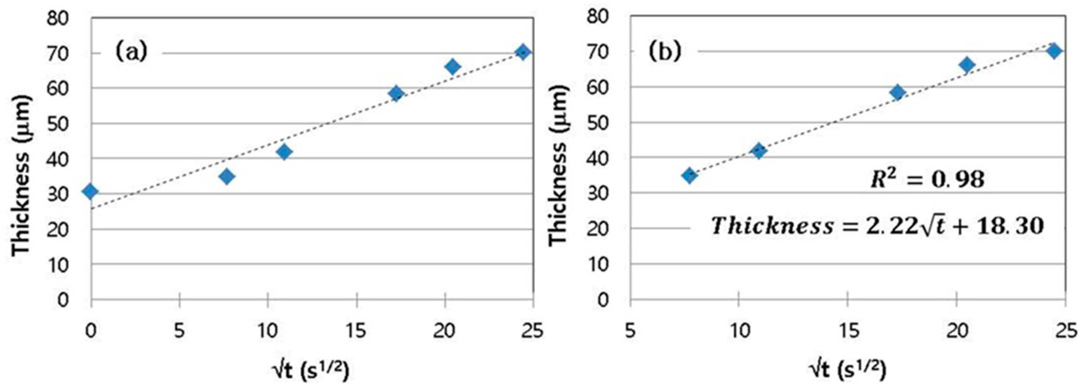
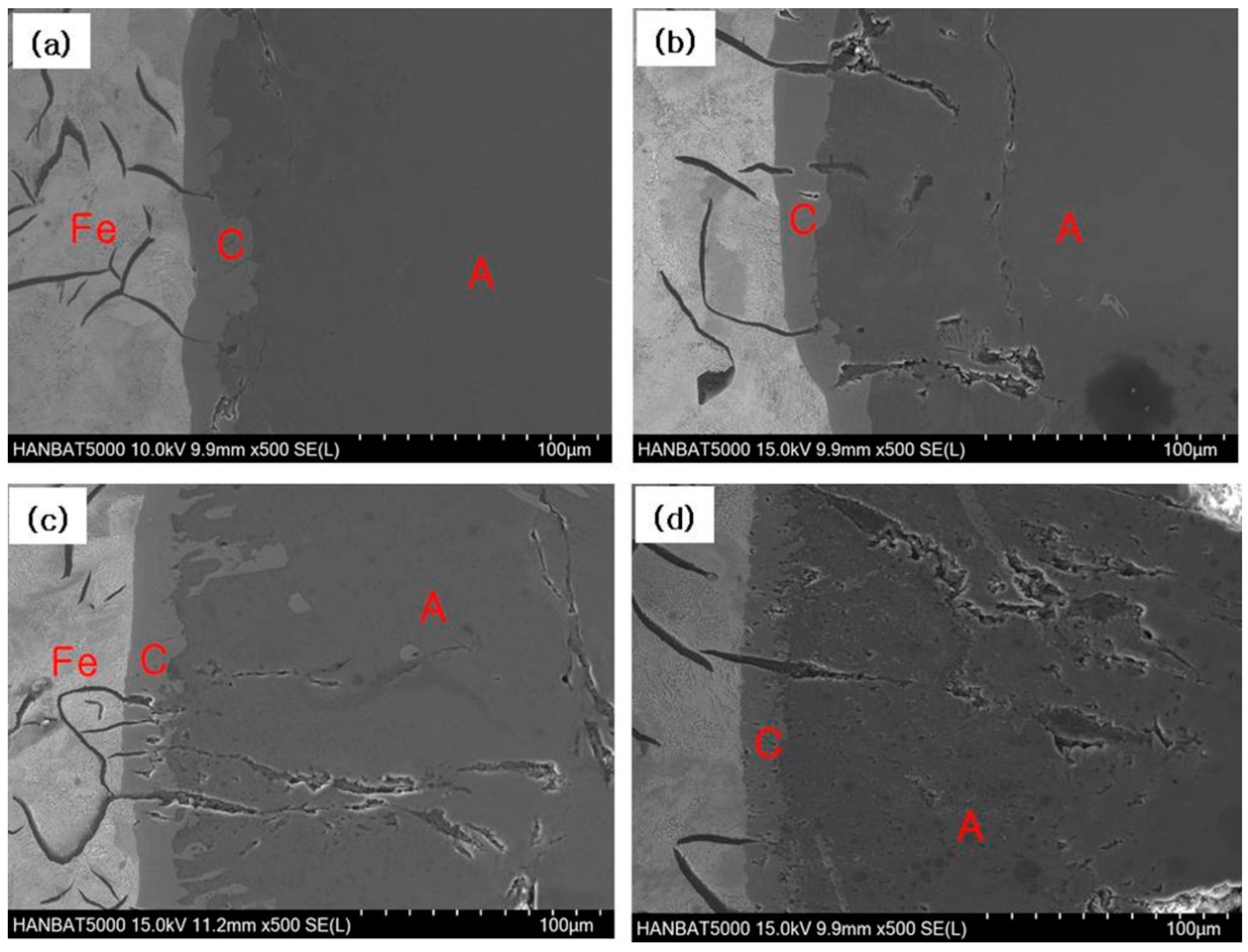
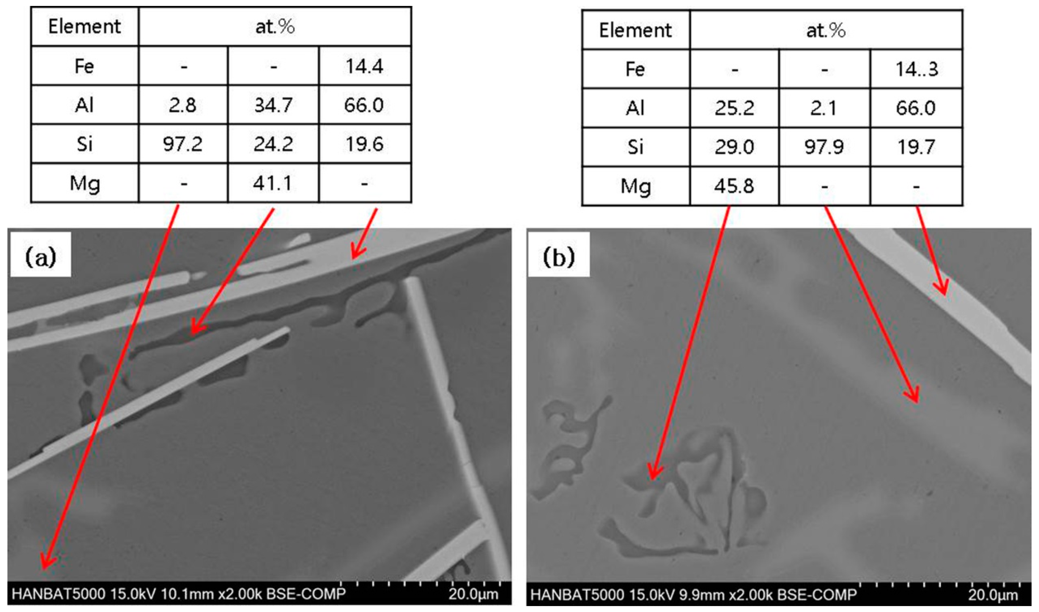
3.2. Cast Iron/Al–Si Alloy Interface

The reaction experiment between the cast iron insert and the Al–Si alloy melt was carried out in the same manner as the experiment between the cast iron and the pure aluminum melt. Figure 6 shows the difference of interfacial microstructures with the change of holding time. It is clearly observed that an interfacial compound was formed even at a short holding time, and the thickness of the compound was slightly increased as the holding time was increased. However, it can be seen from Figure 7 that there is a clear difference in the growth rate of the thickness of the interfacial compound. In the study of the formation of interfacial compounds due to the reaction of steel and Al, it has been reported that Si addition reduces the compound thickness increase [15,17]. Figure 7 also indicates that the total thickness of the interfacial compound is not accurately proportional to √t, and this may be related to the presence of two or more compounds at the interface.
In the case of the interfacial compound, the results of EDS analysis in Table 3 indicate that Si is included in addition to Fe and Al. Therefore, this compound is considered to be different from the Al5Fe2 phase, and it is believed to be close to the Al4.5FeSi (Al5FeSi) or Al8Fe2Si phase when compared with the results in the literature [3,17]. In SEM micrographs in Figure 6, the interfacial compound appears to consist of one phase, but two or more phases may be present in combination. The EBSD analysis result in Figure 8 and Figure 9 led to the conclusion that the major interfacial compounds consist of Al8Fe2Si and Al4.5FeSi [12,13,14,15,16,17,18], depending on the holding time. In specimens with relatively short holding times, Al5Fe2 and Al13Fe4 phases were not observed, and the interfacial compounds were mainly composed of Al8Fe2Si and Al4.5FeSi phases. On the other hand, a considerable amount of Al5Fe2 and some Al13Fe4 phases were also formed in the specimen with a long holding time (10 min), as shown in Table 4. Therefore, it is concluded that AlFeSi compounds, such as Al8Fe2Si and Al4.5FeSi, are initially formed, but AlFe compounds, such as Al5Fe2 and Al13Fe4, require sufficient time to form.
As in the case of pure aluminum, an iron-containing compound is also formed in the Al–Si alloy region slightly away from the interface (Figure 10). Of course, the Al–Si alloy contained about 7% Si and a little Mg, so that the eutectic Si and Mg2Si phases were also formed.
The needle-shaped iron-containing compound is postulated to be the Al4.5FeSi (Al5FeSi) phase, and it has been well known to be harmful on the mechanical properties of aluminum alloys [19,20]. This result is indicative of the fact that the mechanical properties of the aluminum alloy region of the Fe/Al compound cast component may be degraded.

4. Conclusions

The reaction between the cast iron insert and the aluminum melt formed a compound at the interface, which was observed to form a significant thickness in a relatively short holding time. The interfacial compound is assumed to be mainly within the Al5Fe2 phase, and its thickness increase rate is approximately proportional to the root of the holding time, so it seems to be mainly determined by the diffusion rate of the elements. Meanwhile, at the aluminum matrix, slightly away from the interface, a compound, which is regarded as the Al3Fe phase, was formed in a needle shape.
Experiments using Al–Si alloy melt showed similar results to those using pure aluminum melt. That is, the thickness increase rate of the compound region tended to be proportional to the root of the holding time, but the growth rate was significantly lower than that of pure aluminum. In addition, due to the alloying element Si, the main interfacial compounds were observed to be the Al4.5FeSi, Al8Fe2Si and Al5Fe2 phases. It was also found that the type and the relative amount of the interfacial phases varied with the holding time. In the aluminum alloy matrix, a little away from the interface, the acicular Al4.5FeSi phase, along with the eutectic Si and Mg2Si phases, were observed.

Author Contributions

Conceptualization, J.-M.K. and J.-S.S.; methodology, J.-M.K.; investigation, J.-M.K. and K.S.; writing—original draft preparation, J.-M.K.; writing—review and editing, J.-M.K.; funding acquisition, J.-M.K. and J.-S.S. All authors have read and agreed to the published version of the manuscript.

Funding

This work was supported by the National Research Foundation of Korea (NRF) grant, funded by the Korean government (MSIP) (NRF-2012M2A8A5025822).

Conflicts of Interest

The authors declare no conflict of interest.

References

  1. Dangi, B.; Brown, T.W.; Kulkarni, K.N. Effect of silicon, manganese and nickel present in iron on the intermetallic growth at iron-aluminum alloy interface. J. Alloys Compd. 2018, 769, 777–787. [Google Scholar] [CrossRef]
  2. Jiang, W.; Li, G.; Jiang, Z.; Wu, Y.; Fan, Z. Effect of heat treatment on microstructures and mechanical properties of Al/Fe bimetal. Mater. Sci. Technol. 2018, 34, 1519–1528. [Google Scholar] [CrossRef]
  3. Moosavi-Khoonsari, E.; Jalilian, F.; Paray, F.; Emadi, D.; Drew, R.A.L. Cast joining of cast iron to aluminium casting matrix. Mater. Sci. Technol. 2011, 27, 1707–1717. [Google Scholar] [CrossRef]
  4. Yeremenko, V.N.; Natanzon, Y.V.; Dybkov, V.I. The effect of dissolution on the growth of the Fe2Al5 interlayer on the solid iron-liquid aluminium system. J. Mater. Sci. 1981, 16, 1748–1756. [Google Scholar] [CrossRef]
  5. Yan, M.; Fan, Z. Review: Durability of materials in molten aluminium alloys. J. Mater. Sci. 2001, 36, 1748–1756. [Google Scholar] [CrossRef]
  6. Denner, S.G.; Jones, R.D. Kinetic interactions between aluminium and iron/steel for conditions applicable to hot-dip aluminizing. Met. Technol. 1977, 4, 167–174. [Google Scholar] [CrossRef]
  7. Ding, Z.; Hu, Q.; Lu, W.; Ge, X.; Cao, S.; Sun, S.; Yang, T.; Xia, M.; Li, J. Microstructural evolution and growth behavior of intermetallic compounds at the liquid Al/Solid Fe interface by synchrotron X-ray radiography. Mater. Charact. 2018, 136, 157–164. [Google Scholar] [CrossRef]
  8. Jiang, W.; Fan, Z.; Li, G.; Liu, X.; Liu, F. Effects of hot-dip galvanizing and aluminizing on interfacial microstructures and mechanical properties of aluminum/iron bimetallic composites. J. Alloys Compd. 2016, 688, 742–751. [Google Scholar] [CrossRef]
  9. Takata, N.; Nishimoto, M.; Kobayashi, S.; Takeyama, M. Morphology and formation of Fe-Al intermetallic layers on iron hot-dipped in Al-Mg-Si alloy melt. Intermetallics 2014, 54, 136–142. [Google Scholar] [CrossRef]
  10. Shin, J.; Kim, T.; Lim, K.; Cho, H.; Yang, D.; Jeong, C.; Yi, S. Effects of steel type and sandblasting pretreatment on the solid-liquid compound casting characteristics of Zn-coated steel/aluminum bimetals. J. Alloys Compd. 2019, 778, 170–185. [Google Scholar] [CrossRef] [Green Version]
  11. Cheng, W.J.; Wang, C.J. Observation of high-temperature phase transformation in the Si-modified aluminide coating on mild steel using EBSD. Mater. Charact. 2010, 61, 467–473. [Google Scholar] [CrossRef]
  12. Takata, N.; Nishimoto, M.; Kobayashi, S.; Takeyama, M. Crystallography of Fe2Al5 phase at the interface between solid Fe and liquid Al. Intermetallics 2015, 67, 1–11. [Google Scholar] [CrossRef]
  13. Bouayad, A.; Gerometta, C.; Belkebir, A.; Ambari, A. Kinetic interactions between solid iron and molten aluminium. Mater. Sci. Eng. A 2003, A363, 53–61. [Google Scholar] [CrossRef]
  14. Deqing, W.; Ziyuan, S.; Longjiang, Z. A liquid aluminum corrosion resistance surface on steel substrate. Appl. Surf. Sci. 2003, 214, 304–311. [Google Scholar] [CrossRef]
  15. Cheng, W.J.; Wang, C.J. Effect of silicon on the formation of intermetallic phases in aluminide coating on mild steel. Intermetallics 2011, 19, 1455–1460. [Google Scholar] [CrossRef]
  16. Soderhjelm, C. Multi-Material Metal Casting: Metallurgical Bonding Aluminum to Ferrous Inserts. Ph.D. Thesis, Worcester Polytechnic Institute, Worcester, MA, USA, 25 April 2017. [Google Scholar]
  17. Springer, H.; Kostka, A.; Payton, E.J.; Raabe, D.; Kaysser-Pyzalla, A.; Eggeler, G. On the formation and growth of intermetallic phases during interdiffusion between low-carbon steel and aluminum alloys. Acta Mater. 2011, 59, 1586–1600. [Google Scholar] [CrossRef]
  18. Fedian, D.; Josse, C.; Nquyen, P.; Gey, N.; Ratel-Ramond, N.; Parseval, P.; Thebault, Y.; Malard, B.; Lacaze, J.; Salvo, L. Chinese script vs plate-like precipitation of beta-Al9Fe2Si2 phase in an Al-6.5Si-1Fe alloy. Metal. Mater. Trans. A 2015, 46, 2814–2818. [Google Scholar] [CrossRef] [Green Version]
  19. Sacinti, M.; Cubuklusu, E.; Birol, Y. Effect of iron on microstructure and mechanical properties of primary AlSi7Mg0.3 alloy. Int. J. Cast Met. Res. 2016, 59, 1586–1600. [Google Scholar] [CrossRef]
  20. Sakow, S.; Tokunaga, T.; Ohno, M.; Matsuura, K. Microstructure refinement and mechanical properties improvement of Al-Si-Fe alloys by hot extrusion using a specially designed high-strain die. J. Mater. Process. Tech. 2020, 277, 1116447. [Google Scholar] [CrossRef]
Figure 1. Schematic diagram of cast iron/liquid aluminum interaction experiment.
Metals 10 00759 g001
Figure 2. SEM-EDS analysis of our cast iron/liquid aluminum interface isothermally heated at 720 °C for different times: (a) 0 min, (b) 1 min, (c) 5 min, (d) 10 min (C refers to the interfacial compound region and A refers to the aluminum base region near the interface in Table 2).
Metals 10 00759 g002
Figure 3. SEM micrographs and EDS line profile from the cast iron/liquid aluminum interface isothermally heated at 720 °C for different times: (a) 1 min and (b) 5 min.
Metals 10 00759 g003
Figure 4. SEM-EDS analysis of Fe-containing phases formed a little away from the cast iron/liquid aluminum interface isothermally heated at 720 °C for different times: (a) 1 min and (b) 5 min.
Metals 10 00759 g004
Figure 5. Thickness changes of compounds formed at the cast iron/liquid aluminum interface with heating time at 720 °C: the specimen with a holding time of 0 min is included (a) and not included (b).
Metals 10 00759 g005
Figure 6. SEM-EDS analysis of cast iron/liquid Al–Si alloy interface isothermally heated at 720 °C for different times: (a) 0 min, (b) 1 min, (c) 5 min, (d) 10 min (C refers to the interfacial compound region and A refers to the aluminum base region near the interface in Table 3).
Metals 10 00759 g006
Figure 7. Thickness changes of compounds formed at the cast iron/liquid Al (pure) and at the cast iron/Al–Si alloy (A356) interface with heating time at 720 °C.
Metals 10 00759 g007
Figure 8. EBSD phase distribution maps of compounds formed at the cast iron/liquid Al–Si alloy interface isothermally heated at 720 °C: (a) for 1 min, (b) 5 min.
Metals 10 00759 g008
Figure 9. EBSD phase distribution map of compounds formed at the cast iron/liquid Al–Si alloy interface isothermally heated at 720 °C for 10 min.
Metals 10 00759 g009
Figure 10. SEM-EDS analysis of cast iron/liquid Al–Si alloy interface isothermally heated at 720 °C for different times: (a) 5 min, (b) 10 min.
Metals 10 00759 g010
Table 1. Chemical compositions of gray cast iron (insert) and A356 casting alloy (wt.%).
AlloyCSiMgMnFeAl
Cast Iron2.650.31-0.15Balanced-
A356-6.960.31--Balanced
Table 2. Concentrations (at.%) of intermetallic compounds (C) at the interface of cast iron/liquid aluminum and aluminum matrix (A) near the interface with respect to the holding time (the numbers in parenthesis indicate weight percent).
Time0 min1 min5 min10 min
LocationCACACACA
Fe23.0 (38.2)0.2 (0.4)23.5 (38.9)0.7 (1.4)26.5 (42.8)0.2 (0.4)26.4 (42.6)0.2 (0.3)
Al77.0 (61.8)99.8 (99.6)76.5 (61.1)99.3 (98.6)73.5 (57.2)99.8 (99.6)73.6 (57.4)99.8 (99.7)
Table 3. Concentrations (at.%) of intermetallic compounds (C) at the interface of cast iron/liquid Al–Si alloy and aluminum matrix (A) near the interface with respect to the holding time (numbers in parentheses indicate weight percent).
Time0 min1 min5 min10 min
LocationCACACACA
Fe15.6 (27.4)-16.1 (28.3)-17.5 (30.3)-15.2 (26.8)-
Al67.1 (57.2)97.8 (97.7)67.7 (57.3)92.3 (92.1)68.6 (57.4)98.1 (98.1)66.8 (57.1)98.6 (98.6)
Si17.1 (15.1)1.8 (1.9)16.0 (14.1)7.2 (7.5)13.7 (12.0)1.5 (1.6)17.8 (15.8)0.9 (1.0)
Mn0.2 (0.3)-0.2 (0.3)-0.2 (0.3)-0.2 (0.3)-
Mg-0.4 (0.4)-0.5 (0.4)-0.4 (0.3)-0.5 (0.4)
Table 4. Phase fraction (number) of the compound region at the interface of cast iron/liquid Al–Si alloy shown in Figure 9.
PhaseAl4.5FeSiAl8Fe2SiAl13Fe4Al5Fe2AlFerrite
Fraction0.190.190.140.210.130.14

