Article

Tribological Properties of Ti2AlNb Matrix Composites Containing Few-Layer Graphene Fabricated by Spark Plasma Sintering

1
School of Metallurgy Engineering, Xi’an University of Architecture and Technology, Xi’an 710055, China
2
School of Materials Science and Engineering, Northeastern University, Shenyang 110819, China
3
Titanium Alloy Institute, Northwest Institute for Nonferrous Metal Research, Xi’an 710016, China
*
Authors to whom correspondence should be addressed.
Metals 2020, 10(7), 924; https://doi.org/10.3390/met10070924
Submission received: 5 May 2020 / Revised: 7 July 2020 / Accepted: 8 July 2020 / Published: 9 July 2020

Abstract

:
Ti2AlNb alloys with few-layer graphene were fabricated by spark plasma sintering (SPS) to enhance the tribological properties (TP) of the composite materials. Microstructure characteristics of the original few-layer graphene (FLG), Ti2AlNb powders, and the sintered composites were characterized by X-Ray Diffraction (XRD), scanning electron microscopy (SEM), and Raman spectroscopy. The experimental results indicated that FLGs were homogeneously distributed in the composites. Tribological results indicated that the coefficient of friction (COF) of the composites was reduced as the content of FLG increased. Compared with the pure Ti2AlNb alloy, the average COF of the composite with 1.0 wt.% FLG was decreased by 9.4% and the wear rate was decreased by 36%. Meanwhile, the microstructures of the worn surface showed that TiC particles and friction layers formed by residual FLGs were present on the surface of the composites after tribological test. It is proposed that Ti2AlNb alloys with FLGs presented the enhanced wear resistance.

1. Introduction

In recent years, the Ti2AlNb-based alloy has become one of the preferred materials for aero-engine because of its light weight and high-temperature strength including high fracture toughness, better creep and fatigue resistance, and oxidation resistance [1,2,3]. As the application of the high-temperature moving parts in the aero-engine, the Ti2AlNb-based alloy would be easily worn out. Therefore, the investigation on the wear and friction of the Ti2AlNb-based alloy has become one of the urgent issues to solve.
During past investigations, the self-lubricating metal matrix composites have developed into the most effective way to enhance the tribological properties (TP) of the metal matrix composites [4]. There are many solid lubricants that can improve the wear resistance of the material, but most of them sacrifice the strength while improving the TP of the material [5]. Therefore, choosing an effective solid lubrication additive into the composites, which not only improves the TP but also enhances the strength of the composites, is a huge challenge for improving the comprehensive performance of the Ti2AlNb-based alloy.
As a solid lubricant additive of the composite materials, graphene has attracted much attention because of its high strength, high fracture toughness and large specific surface area (2630 m2/g) [6,7]. Graphene consists of multilayer graphene (MLG) and few-layer graphene (FLG). FLG refers to two-dimensional carbon materials with a thickness of 3–10 layers of C atoms, while MLG has a thickness of more than 10 layers [8]. FLG is more conducive to uniform dispersion during the mixing process. The graphene and its derivatives have been added into the ceramic, polymer and metallic composites [9,10,11,12]. It was found that the mechanical properties of graphene/metal matrix composites have been increased [12]. Besides, choosing graphene as the solid lubricants in the metallic composites to fabricate self-lubricating composites is an efficient way to improve the friction reduction and wear resistance of the mechanical parts [13]. Xu et al. [14] studied the TP of graphene/TiAl-based alloy and found that graphene has low shear and good protective properties, which give it a momentous role in improving the friction and abrasion resistance of the TiAl-based alloy. Zhou et al. [15] studied the effects of MLG and Ag on the lubricating properties of the Ti6Al4V alloy; the results showed that MLG and Ag were continuously melted at high temperature and diffused at the friction interface to form a lubrication film. The lubrication film played a significant role in anti-friction and anti-wear. Zhao et al. [16] investigated the TP of the MLG/γ-TiAl composites under different loads. The results showed that as the content of MLG increased, the wear resistance and the tensile strength of MLG/γ-TiAl were both improved. Consequently, based on the above research, graphene can be used as both the reinforcing phase and lubricating phase to improve the comprehensive performance of the materials [5]. However, there has not been any research on the preparation and TP of FLG/Ti2AlNb composites to date. Previous research about Ti2AlNb-based alloys was mainly focused on the effects of heat processing and heat treatment on microstructure evolutions and mechanical properties; few data were reported on the influence of graphene on the TP of a Ti2AlNb-based alloy.
In this investigation, Ti2AlNb alloys with few-layer graphene were mixed by high-energy ball milling and low-energy ball milling. Then, the mixed powders were consolidated by spark plasma sintering (SPS) at 1100 °C. The microstructures and tribological properties at room temperature of the FLG/Ti2AlNb composites were further investigated and discussed.

2. Experimental Procedure

2.1. Raw Materials

The preparation process of the composites is shown in Figure 1. It mainly contained two stages: (1) preparation of the mixed powders and (2) SPS. In this investigation, FLG were procured from XFNANO Tech. Co., Ltd., (Nanjing, China). The diameter and thickness of FLG are 300 nm and 3–10 nm, respectively. Ti2AlNb powders were used as the matrix materials. Gas-atomized Ti2AlNb pre-alloy powders were procured from Sino-Euro Materials Technologies of Xi’an Co., Ltd. (Xi’an, China). The true chemical compositions of Ti2AlNb powders were 47.09 wt.% Ti, 22.3 wt.% Al, 25.7 wt.% Nb, 4.30 wt.% O, 0.52 wt.% N and 0.09 wt.% H. The density and average particle size of Ti2AlNb powders were 5.30 g/cm3 and 53–180 µm, respectively.

2.2. Preparation of the FLG/Ti2AlNb Powders

Firstly, the planetary ball-milling machine (QM-3SP2) was used to grind the Ti2AlNb pre-alloyed powders through high-energy ball milling for 16 h to increase their specific surface area. The high-energy ball-milling process was carried out in a cylindrical container using lapping balls with diameters of 10 and 4 mm. The speed of high-energy ball milling was 350 rpm and the mass ratio of balls to the powders was 10:1. Then, the different contents of FLG were mixed with the Ti2AlNb pre-alloyed powders by low-energy ball milling. The speed and the time of low-energy ball milling were 200 rpm and 16 h, respectively. All the ball milling processes were carried out under the vacuum condition. The ball-milling cans and balls used for low-energy ball milling were made of zirconia and the mass ratio of balls to the powders was 8:1. Finally, the mixed powders were used to fabricate the composites by SPS in the next step.

2.3. SPS

SPS technique can effectively inhibit grain growth during the sintering process and fabricate composites with an excellent comprehensive performance [17,18]. The mixtures were sintered by SPS using a D.R. Sinter SPS 3.20 (SPS Syntex Inc., Kanagawa, Japan) apparatus. The mixed powders by low-energy ball milling were loaded into the die with a size of Φ20 × 65 mm. SPS process with a vacuum of 10−1 Pa was used to consolidate the powders after low-energy ball milling. The compressive pressure and holding time were 50 MPa and 20 min, respectively. The sintering temperature, heating rate and cooling rate were set as 1100 °C, 50 °C/min and 100 °C /min, respectively. Finally, the sintered composites with dimensions of Φ20 × 10 mm were obtained. The sintered blocks were named as TF0-TF10 according to the FLG content. TF0, TF2, TF4, TF6, TF8 and TF10 are the composites containing FLG of 0, 0.2, 0.4, 0.6, 0.8, and 1.0 wt.%, respectively.

2.4. Tribological Measurements

The dry sliding friction tests were conducted in a ball-on-disk mode using Universal Micro-Tribotester (UMT-3, Bruker, Beijing, China). The experiments were conducted on the ball-on-disk tester for 30 min at ambient temperature. The dimensions of the disk and counterpart ball were Φ20 × 5 and Φ6 mm (HRC58, Ra 0.08 μm), respectively. The material of the disk and counterpart ball were TF0-TF10 (FLG/Ti2AlNb composites) and GCr15 ball, respectively. The chemical compositions of GCr15 ball are shown in Table 1.
After being cleaned and dried, the TP of the composites was investigated at the constant load of 8 N. The automatic measurement of COFs was realized in real time by the computer system of friction tester. The sliding wear rate W (mm3/N mm) was calculated by the following formulas [19]
l = r r 2 d 2 4
V = ( π l 6 ) ( 3 d 2 4 + l 2 )
W = V P S
where r, d, V, P and S are the radius of the GCr15 ball (3 mm), diameter of the worn scar (mm), wear volume (mm3), constant applied load (8 N) and total sliding distance (mm), respectively.

2.5. Characterization

Microstructure characteristics of the FLG/Ti2AlNb composites and the surface of the wear scar were analyzed by the field emission scanning electron microscope (FESEM, Carl Zeiss G300, Jena, Germany) equipped with energy-dispersive spectroscopy (EDS) and backscattered electron images (BSE). X-ray diffraction (XRD, D8 advance, Bruker, Beijing, China) was carried out to investigate the crystalline phases of FLG/Ti2AlNb composites. The radiation source and scanning speed of XRD were Cu Kα and 0.25°/s. Micro-area Raman spectroscopy (He-Ne, 532 nm, 100–3200 cm−1) was adopted (RENISHAW, INVIA, London, UK) to analysis the structure integrity of FLG in the sintered samples. The wear scars of the upper sample balls were tested by an optical microscope (OM, LV150, Nikon, Tokyo, Japan). The compression strength of the alloy was investigated using uniaxial compression tests on an Instron 5500R machinehe (Boston, MA, USA).

3. Results and Discussion

3.1. Microstructures of the Mixed Powders

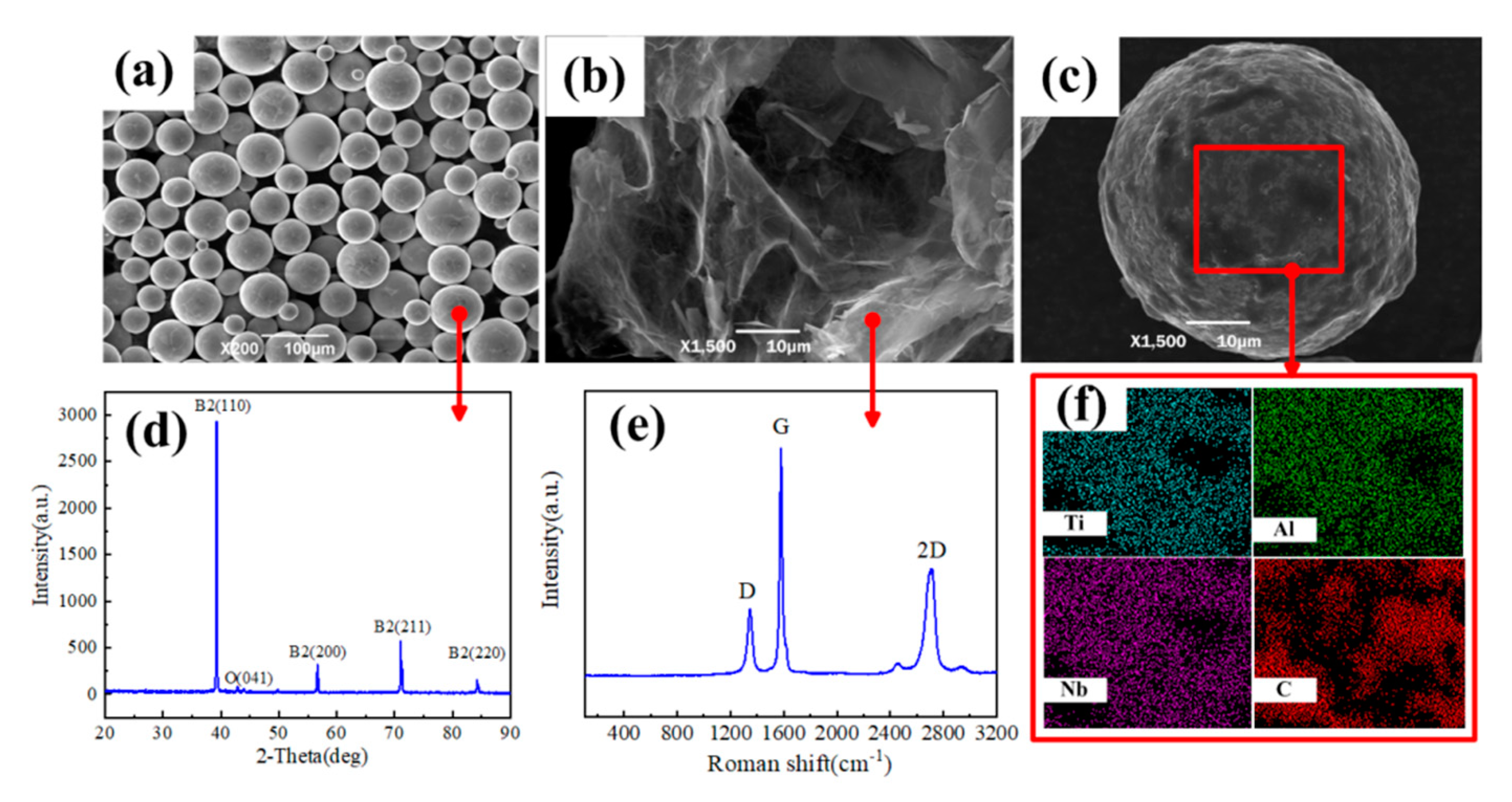
The characterizations of the Ti2AlNb pre-alloy powders, FLG and the mixed powders are shown in Figure 2. The SEM images of the Ti2AlNb pre-alloy powders showed that the Ti2AlNb pre-alloy powders have a regular spherical morphology. There are three different phase types of Ti2AlNb-based alloys: orthorhombic phase (O), hexagonal close-packed phase (α2) and disordered structure bcc phase (β) or ordered body-centered cubic structure phase (B2) [20]. According to the XRD results, the B2 phases were present in the Ti2AlNb pre-alloy powders and only trace O phase existed in the current microstructure. In the Ti2AlNb alloy, B2 phase was retained at a high temperature and the O and α2 phase were retained at a lower temperature [20]. The Ti2AlNb pre-alloy powders were produced at a high temperature, thus the B2 phases were obtained. In the rapid cooling process, only a few B2 phases are transformed into the O phase. The microstructure of FLG (Figure 2b) showed that the surface of FLG presented few wrinkles and folds. From the Raman patterns of FLG (Figure 2e), the raw FLG exhibited typical D, G and 2D bands. The intensity of the 2D band was significantly lower than that of the G band. This means that the few-layer graphene was used in this experiment [21]. Figure 2c shows the morphology of the powder of TF10 after low-energy ball milling. This shows that some black substances were adsorbed on the surface of Ti2AlNb powder. The surface of the powder was analyzed by EDS (Figure 2f) in order to find out whether the black substance is FLG. The result showed that a large amount of C elements was distributed in the region of the spherical powder. This means that FLG was well-distributed on the surface of the Ti2AlNb particles [22].

3.2. Microstructure of the FLG/Ti2AlNb Composites

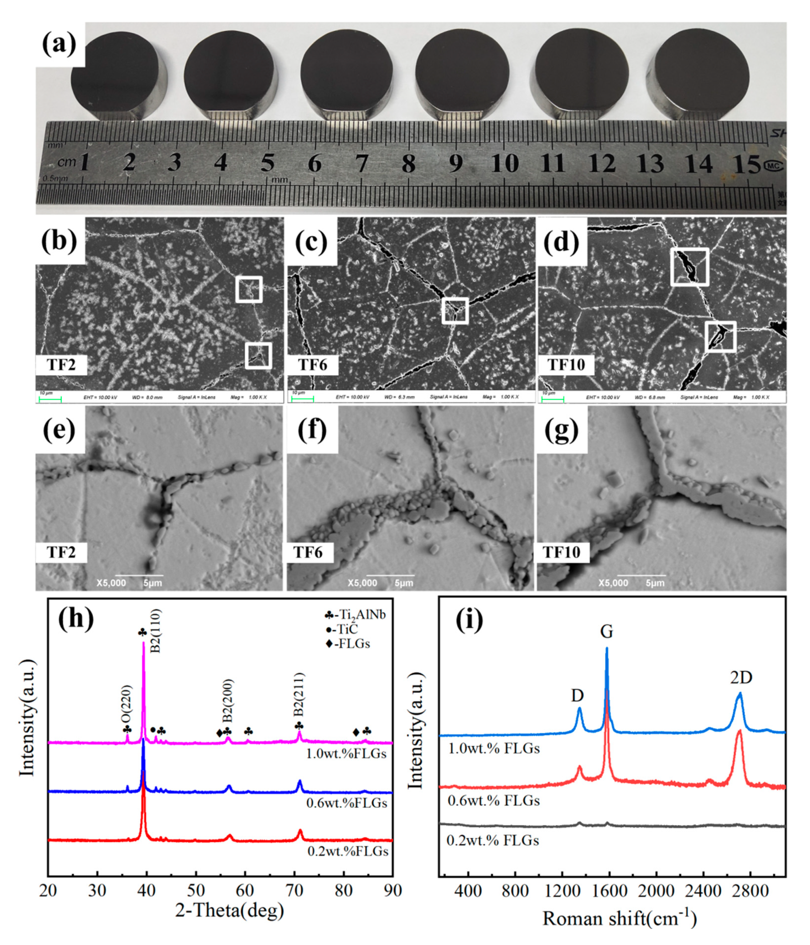
As can be seen from the macroscopic morphologies of the sintered samples (Figure 3a), the diameter of the sintered samples is 20 mm. Table 2 shows the actual and relative density of SPSed composites. It can be seen from Table 2 that the theoretical density of the composite decreases with the increase in FLG content. The variation trend of density of the actually prepared FLG/Ti2AlNb composite is consistent with the theoretical calculation. The density of the TF0 alloy was 97.74%, and the density of composites increased to more than 99% after adding FLGs. As a result, the dense microstructure was observed on the surface without obvious pores (Figure 3a–d). Figure 3b–d presents the SEM images of TF2, TF6 and TF10. It can be seen that, with the addition of FLG, the average grain sizes of the FLG/Ti2AlNb composites were decreased from 92 to 69 μm. The original acicular precipitated phases in the matrix were also gradually decreased. Figure 3e–g presents the BSE images of TF2, TF6 and TF10. It was also found that, with the addition of FLG, more and more particles which are different from the Ti2AlNb matrix were aggregated at the grain boundary. The new spherical substances were evenly distributed at the grain boundary. According to the XRD patterns (Figure 3h) of the sintered composites, a new TiC phase appeared during the SPS process. The content of FLG in the composite is higher, and the XRD intensity of the new TiC phase is clearer. The needle-like O phases which were precipitated from the B2 phase matrix during the cooling process were also found in the XRD results. The quantities of the acicular O phase were decreased with the increase in FLG. Due to lower Gibbs free energy, the new TiC phase was easily produced. The standard free energy (ΔG) of in-situ TiC phase formed by a reaction between FLG and Ti2ANb matrix can be calculated by the following formula [23]
Δ G ( T i C ) = 184000 + 24.21 T
where ΔG and T are the standard Gibbs free energy of TiC and the temperature of the sintering process, respectively. Combined with the formula, ΔG at T = 1373 K in this investigation is −150,759.67 J/mol (1373 × 24.21 = 33,240.33 and 33,240.33 − 184,000 = −150,759.67 J/mol = −150.76 kJ/mol), which is much smaller than 0. This indicates that the reaction of Ti + C = TiC occurs spontaneously [23]. In the current investigation, FLG was reacted with the Ti2AlNb matrix to generate new TiC phases which aggregated at grain boundaries during SPS.
Raman spectroscopy was used to explore the microstructure and composition of the black substances at grain boundary (shown in Figure 3i). Three obvious characteristic peaks including D, G and 2D band (1350, 1591 and 2692 cm−1) of the FLGs were detected in the sample of TF6 and TF10. Generally, the number of layers of graphene is often determined by the morphology of the 2D peak. The 2D peak of FLG is relatively sharp. For multilayer graphene, the 2D peak appears peak-splitting [24]. The above results proved that there was residual FLG in SPSed samples. In previous studies, ID/IG (the ratio of D to G intensity) is used to assess the quality and structural integrity of graphene. In order to calculate ID/IG accurately, Gaussian quadrature was used for calculate the ratio. The result showed that ID/IG was changed before (0.47) and after SPS (0.24) of TF6, which means that the structure of partial FLG was destroyed obviously during sintering [25,26,27]. ID/IG was almost unchanged before (0.47) and after SPS (0.43) of TF10, which means that FLG was retained in TF10.

3.3. Tribological Properties and Antifriction Mechanism of the Composites

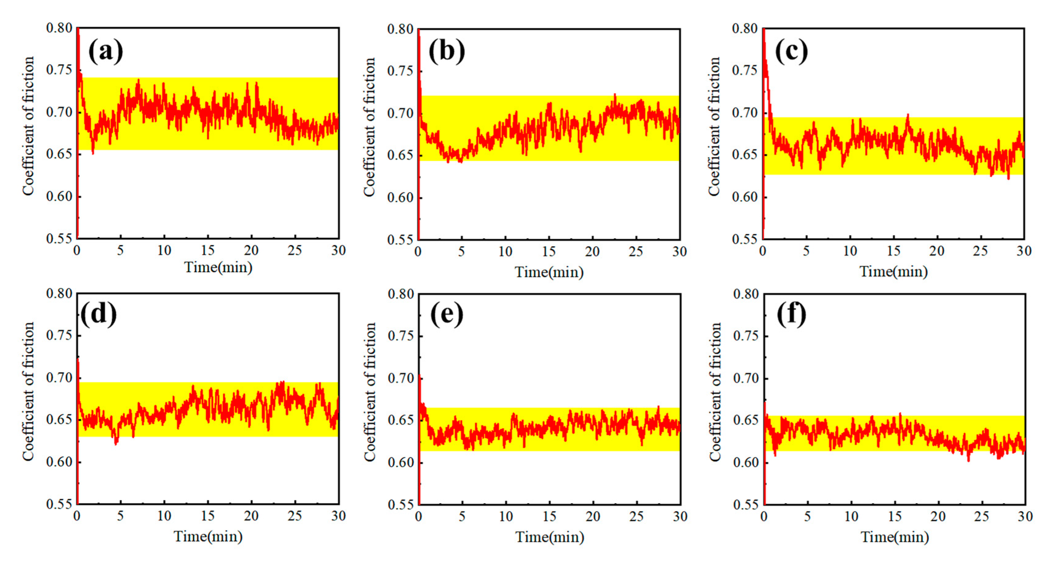
As can be seen from the typical coefficient of friction (COF) (Figure 4), the fluctuation range of COFs was gradually decreased with the increase in FLG wt.%. Compared with the TF0 sample, TF10 (Figure 4f) had the smallest COF, indicating that the contact interface state was more stable. Figure 4a shows that COFs fluctuated violently at the initial stage. With the extension of sliding time, the COFs were gradually stabilized around a constant value after 10 min. With the addition of FLG (Figure 4b–f), the sharp fluctuation time of the COFs was decreased. When FLG wt.% was less than 0.6 wt.%, it can be seen from the figure (Figure 4b–d) that the COFs of the composites still fluctuated violently in the course of friction, which was caused by the instability of the friction layer [28]. When the FLG wt.% was increased to 0.8 wt.%, it was observed that in the typical COFs curves of TF8 (Figure 4e) and TF10 (Figure 4f) the COFs tended to be stable, indicating that the composite materials had stable friction layers.
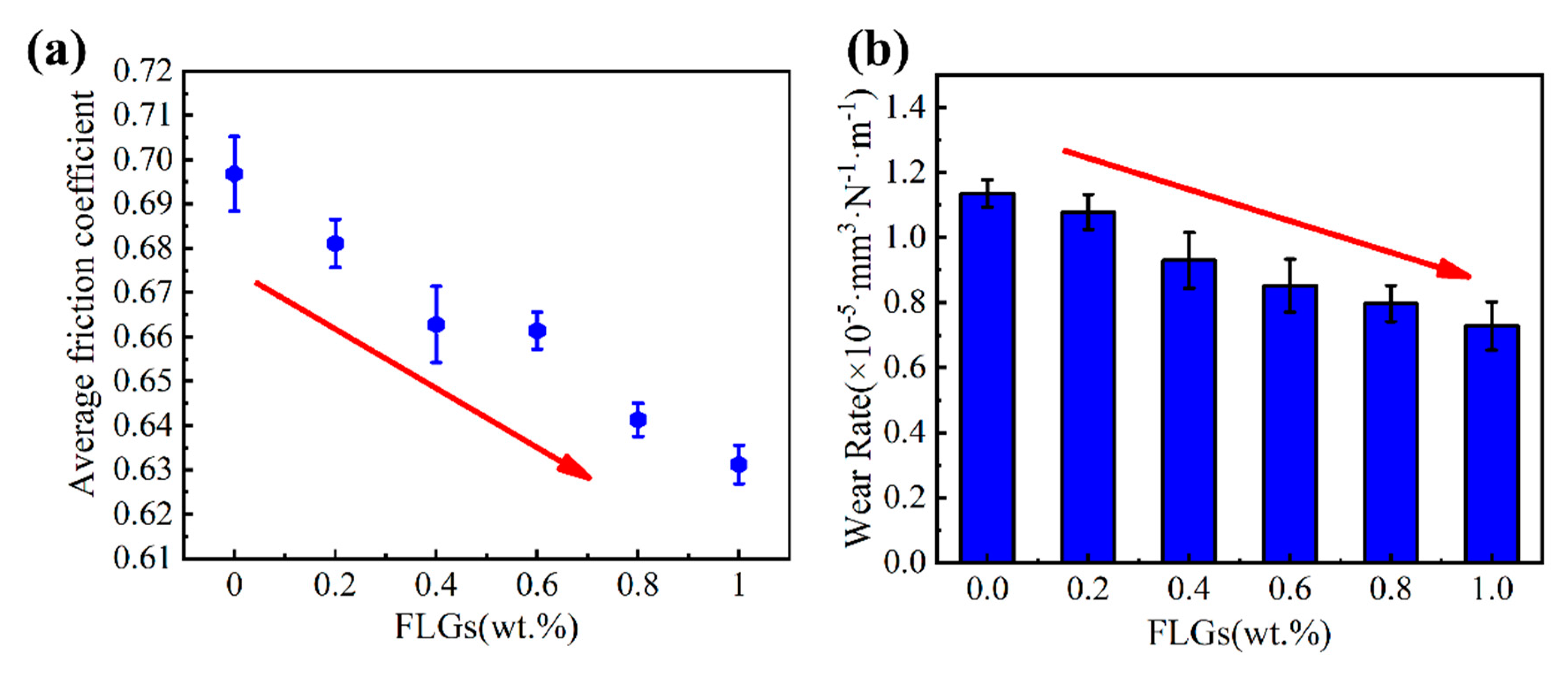
Figure 5a,b shows the average COFs and wear rates of the FLG/Ti2AlNb composites, respectively. According to the figures, the average COFs and wear rates showed a similar trend. With the addition of FLGs, the average COFs were gradually decreased from 0.70 to 0.63, and the wear rates were decreased from 1.1 × 10⁻⁵ to 0.73 × 10⁻⁵ (mm3·N−1·m−1). Compared with the sample of TF0, TF10 had the smallest COF and wear rate, with a reduction of 9.4% and 36%, respectively. This shows that the addition of FLG is beneficial to the wear resistance of composites.
Table 3 shows the effect of different additions on the relative wear resistance of the composite material. Anti-friction effects of average unit mass fraction (AFE) were calculate as Formula (4)
A F E = 1 n i = 1 n [ W p i W p 0 W p 0 / ( C i C 0 ) ]
where Wpi is the wear resistance without reinforced phase in matrix material, Wp0 is the wear resistance of the matrix material or the minimum content of reinforced phase in matrix material and C is the amount of the reinforced phase. It can be seen from Table 3 that FLG with unit mass fraction has the best effect in improving the wear resistance of composite materials, and FLG with unit mass fraction has a significant effect on reducing wear, reaching 73.49%. This is far better than the anti-wear effect of TiB2, TiC, TiC + TiB and C-BN. It also shows that FLG is a significant additive for reducing wear. In order to solve the joint optimization problem of strength and wear resistance, the FLG/Ti2AlNb composite materials of TF0-TF10 were tested under room temperature compression (strain rate of 1 × 10⁻³ s−1). The results were shown in Table 4. As seen from the table, the ultimate compressive strength of the composite materials increased after FLGs were added. The ultimate compressive strength of TF10 decreased slightly. Most solid lubricant additives reduced friction while significantly reducing the strength of materials. It can be seen that the graphene solved the problem of most solid lubricants. The volume of the friction and wear (V) between the base and the spherical surface can be expressed by the formula
d V d s = k s W 3 σ s
where ks is the wear constant, W is the load at each contact point, and σs is the compression yield limit of soft material. According to Formula (5), the wear volume of the composite is inversely proportional to the compression yield limit of the material, so the improvement in the strength of the composite improves the wear resistance. Since a small amount of in-suit TiC particles were generated during the SPS process, TiC, which was a hard reinforcing phase, can improve the strength and hardness of the composite materials [29,30]. Consequently, a small part of the enhancement of the strength of the composites was caused by the TiC phase. The in-situ TiC has a certain effect on improving the wear resistance of the composite. Due to the small amount of in-situ TiC, the improvement in the tribological properties of the composite mainly depended on the residual FLG. This shows that the addition of FLG not only can improve the strength of the composite, but also improve its wear resistance.
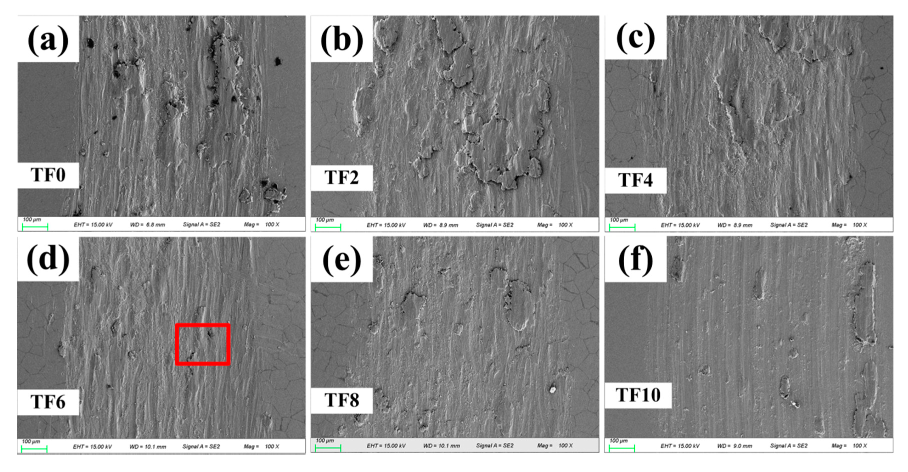
Figure 6 shows the SEM images of the worn surface morphologies. The results show that, with the addition of FLG, the wear mechanism has changed, and the severity of plastic deformation gradually decreased. As shown in Figure 6a, some deep scratches, wear particles and pits were found on the wear surface of composite materials, indicating that the main wear mechanism is abrasive wear. The hardness of GCr15 ball was much higher than that of pure Ti2AlNb, which was the main reason for the wear appearance of the surface. The bulge on the surface of the ball induces ultra-high-contact stress, resulting in a deeper combination and pits. When the contents of adding FLG in the composites were less than 0.6 wt.% (Figure 6b–d), some exfoliated flake-like fragments were repeatedly rolled and attached to the worn surface, forming a discontinuous lamellar tribofilm. There were shallow scratches and pits on the surface of the abrasion, and different sizes of the island-like abrasive debris were daubed on the surface. When the content of FLG increased (Figure 6e,f), the surface of the friction layer became flat and the scratches and pits of the surface became shallower.
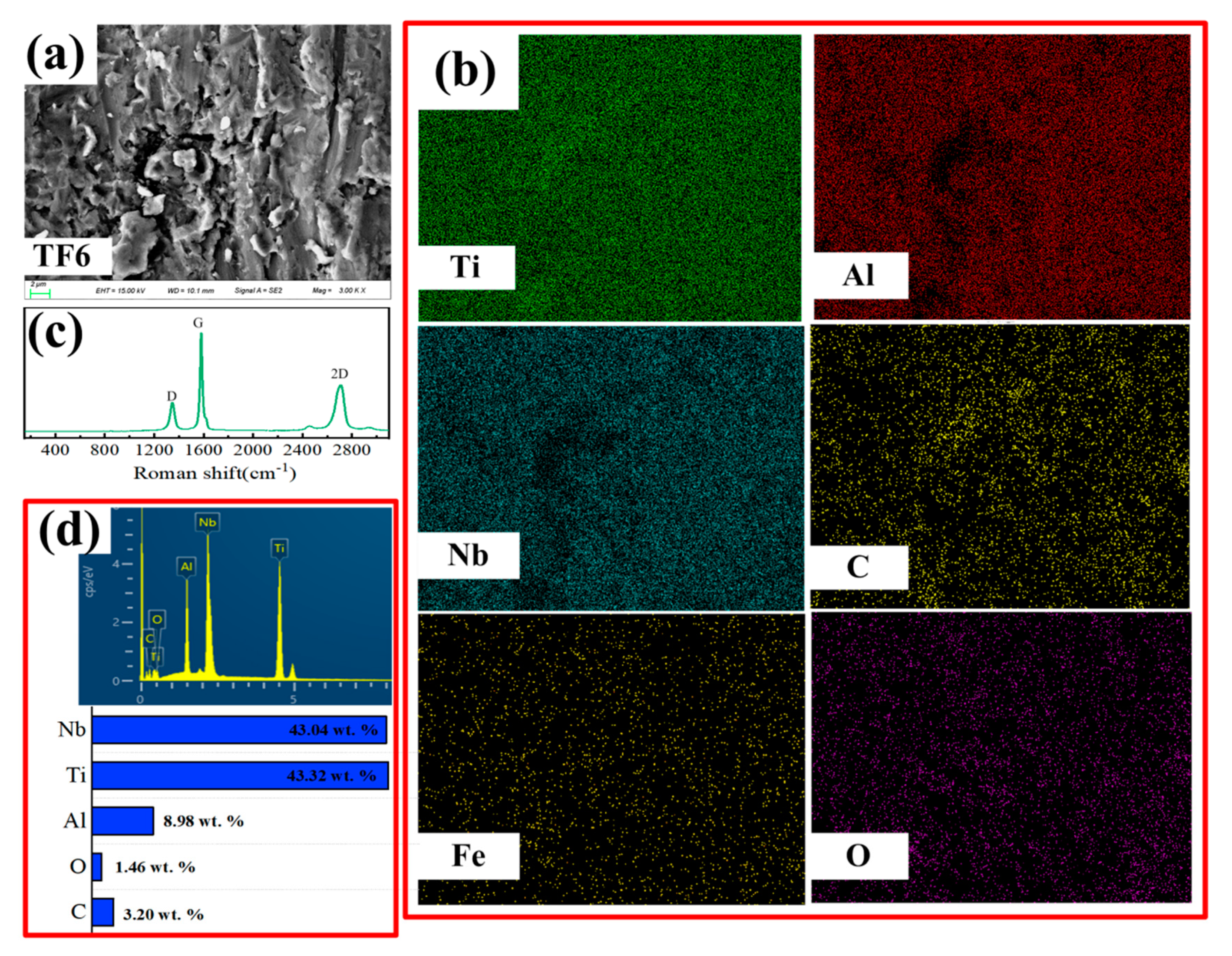
In order to understand the friction-wear mechanism of this process, SEM, EDS and Raman analysis (Figure 7) were performed on the surface of TF6 enlargement. As can be seen in Figure 7b, the C elements were not uniformly distributed. Since the peaks in D, G and 2D, detected by Raman spectroscopy (Figure 7c) on the worn surface, correspond to the characteristic peaks in the original FLG, the existence of FLG at the wear track is proved. The friction film formed by FLG is discontinuous. Fe element was also detected in this area, indicating that adhesive wear occurred. It can be seen from the mass percentage of surface elements (Figure 7d) that the content of the C element is higher than the mass percentage of FLGs which were added into the composites. This shows that FLG will be squeezed to the friction surface in the process of friction. With the addition of the FLG, tribofilm were formed on the wear track area. Fewer and shallower scratches on the worn surface of TF8 (Figure 6e) and TF10 (Figure 6f) were covered by a continuous tribofilm, which demonstrated that the main wear mechanism has changed to the cooperation of abrasive wear and adhesive wear.
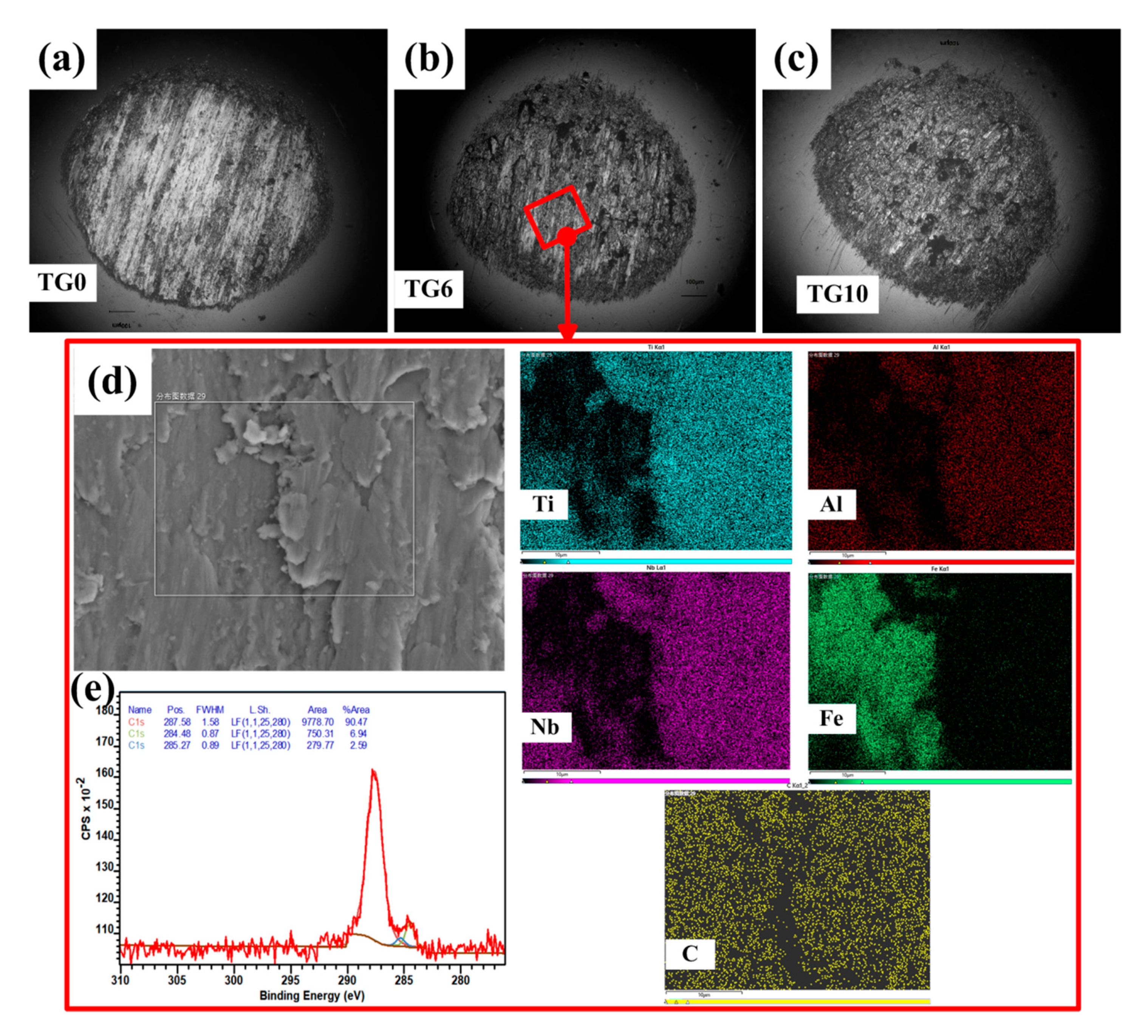
In order to explore the wear mechanism in the sliding friction process, the wear scars (Figure 8) and wear debris (Figure 9) of TF0, TF8 and TF10 were further analyzed by SEM and EDS. It can be seen that (Figure 8a) many deep scratches and furrows along the sliding direction were present on the worn surface of TF0. With the addition of FLGs, the adhered black substances were appeared on the wear scars of GCr15 balls for TF8 (Figure 8b) and TF10 (Figure 8c), and there were also wear particles and protrusions on the worn surface. However, as the content of FLGs increased, the wear scars of TF8 and TF10 along the sliding direction became shallower. It is even difficult to find wear scars in TF10 (Figure 8c). From Figure 8d, it can be seen that a large amount of Ti, Al and Nb elements were distributed on the worn area, which indicated that the adhesion wear was taken in the Ti2AlNb matrix composites. Meanwhile, C element was detected on the surface of wear scars of the GCr15 ball (Figure 8d), which was due to the transformation of C element from FLG to the grinding ball during the friction process. Figure 8e was the XPS spectra of C elements on the worn surface of GCr15 ball of TF6. As can be seen, there were three peaks in the C1s spectrum, the positions of which were 287.58, 284.48 and 285.27 eV. Among them, 285 eV was the standard peak in C and 287.6 eV was the state of C=O, and 284.48 eV was the binding energy of graphene. It indicated that there was a trace of graphene on the worn surface. It is further proved that the graphene in the composite formed a transfer film of C elements on the surface of the wear surface of the GCr15 ball during the friction process. An anti-wear protective layer that can decrease shear and normal stress was formed on the sliding contact interface [19,32,33,34], which is beneficial for the reduction in COF and the wear rate of the FLG/Ti2AlNb composites. Since TiC and residual FLGs were found in the XRD patterns of the composites, it was speculated that the synergistic effect of TiC and residual FLG could improve the TP of the composite materials. The lower wear rate of TF8 and TF10 might be due to the homogeneous distribution of residual graphene in the friction layers, which will increase the TP of TF8 and TF10. Based on the above results, TF10 has the best tribological performance.
SEM and EDS images of the wear debris were shown in Figure 9. The Ti2AlNb alloy (TF0) has a large abrasive particles and wear debris. The wear debris was formed by the microcutting and abrasive. Thus, the mechanism of the FLG/Ti2AlNb composites fabricated by SPS during friction process is abrasive wear. Figure 9b indicated that the main wear debris received from TF6 were fine particles. Compared with TF0, the lamellar particles of TF6 are significantly smaller. The SEM and EDS images (Figure 9d) showed that the Fe element was detected in the abrasive particles. The trace amounts of C were detected in the abrasive particles due to the addition of FLGs. It can be concluded that the wear debris of TF6 should be the mixture of the scrap from the GCr15 ball and Ti2AlNb-based alloy, and the tiny and flattened TiC particles. For TF10, the tiny debris was produced and most of the debris were lamellar (Figure 9c). This shows that the debris was mainly produced from the friction layer of TF10, and not the matrix of TF10. Multilayer substances which attached to extremely fine particles in the abrasive debris of TF10 were found. From the results of EDS in Figure 9c, the smog-like substance contained extremely high C content, it further confirmed that the residual FLGs were present in TF10. The surface of TF10 was crushed and destroyed in the friction process, and the FLGs in the composites were released. With the continuous grinding of GCr15 ball, FLGs, which were evenly ground and attached to the friction layer, played a good lubrication role.
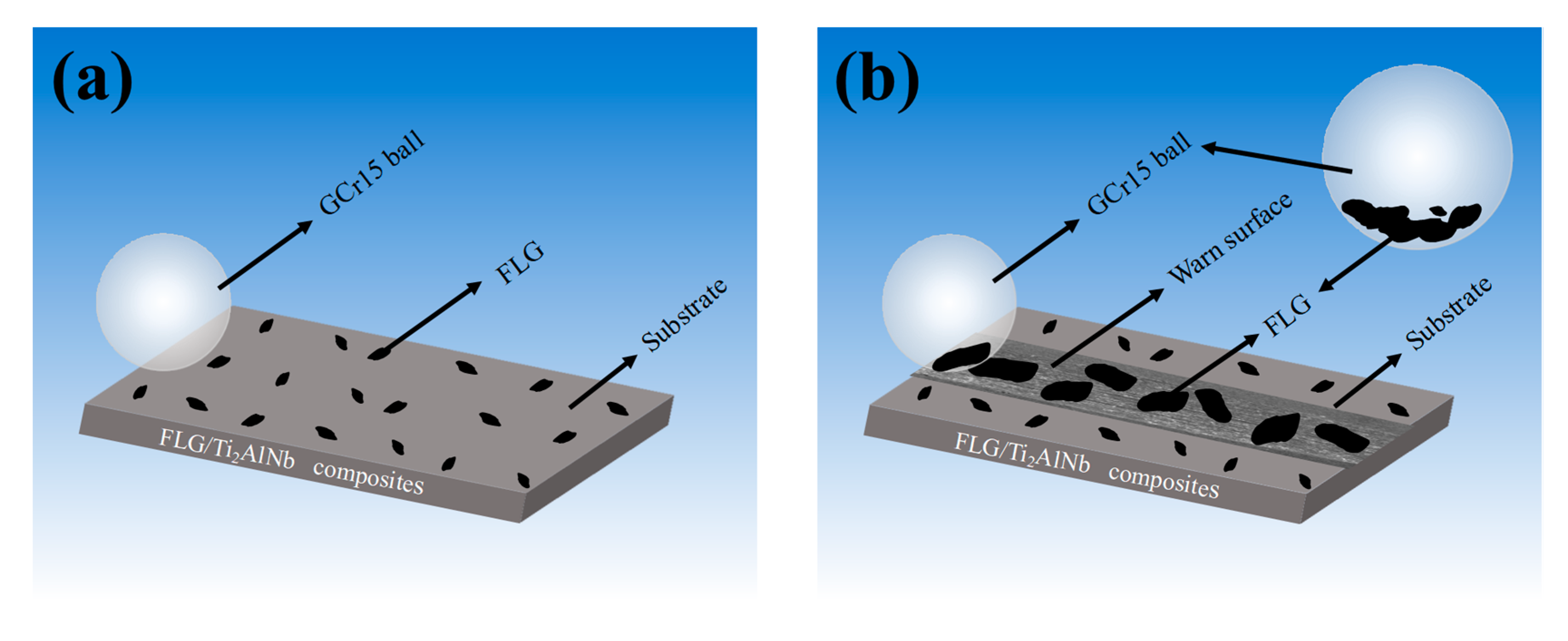
According to these results, it can be proposed that FLGs have the benefit of improving the TP of the FLG/Ti2AlNb during the wear process. Figure 10 shows the anti-friction mechanism diagram of FLG/Ti2AlNb composites. As was shown in Figure 10a, FLGs were evenly distributed on the unworn surface of the FLG/Ti2AlNb composites (seen in Figure 2). In this investigation, the hardness of GCr15 pellets was 62HRc (760 Hv), which was higher than that of FLG/Ti2AlNb (424.3 Hv–557.6 Hv). At the beginning of the wear process, under constant pressure, the raised portion of the GCr15 ball would penetrate the surface of the FLG/Ti2AlNb composites by ploughing, removing the softer matrix material and forming a rough worn surface. It is also the reason that the COFs of the FLG/Ti2AlNb composites fluctuated greatly at the beginning of the frictional process (about 0–5 min). Due to the excellent lubrication properties of FLGs, the large FLGs can be retained on the worn surface [19,32,33,34]. With cyclic stress of the subsequent friction process, a small amount of FLGs would be exfoliated along with the Ti2AlNb matrix and become wear debris during wear. The remaining FLGs could be expanded along the sliding direction (Figure 10b). Finally, as seen from Figure 6d–f and Figure 10b, the different contents of the island-like plates of FLGs were evenly distributed on the wear surface. During the stable friction process (5–30 min), the thin transfer films of C elements were formed on the surface of the grinding GCr15 ball in contact with the composite material (Figure 8a–c). An anti-wear protective layer that can decrease shear stress and normal stress is formed on the sliding contact interface [19], thus greatly reducing the COF and the wear rate of FLG/Ti2AlNb matrix (Figure 5).

4. Conclusions

The Ti2AlNb matrix composites containing different contents of FLGs were mixed by ball-milling and fabricated by SPS. During the process of SPS, most of the FLGs were still retained at high pressure and temperature, and a new phase of TiC was present due to the in-situ reaction between Ti2AlNb and FLGs. The results showed that the addition of FLGs and in-situ TiC can improve the ultimate compressive strength of composite materials. It is also beneficial for improving the wear resistance of materials. By comprehensive analysis of the microstructure and friction behavior of the composite, TF10 has the best TP. Under the normal load of 800 g and the sliding velocity of 200 r/min, the average COF and wear rate of TF10 are 0.63 and 0.73 × 10⁻⁵ mm3·N−1·m−1, respectively. When the content of FLG was less than 0.6 wt.%, the main wear mechanisms of the FLG/Ti2AlNb composites were the synergistic effect of abrasive wear and adhesive wear. The wear surface could not form a complete and continuous anti-friction layer. While the addition of the FLG increased (TF8 and TF10), the friction surface of the composite material formed a continuous friction layer. For TF10, most of the debris was mainly caused by the peeling of the friction layer.

Author Contributions

W.W., S.X. and Q.W. conceived and designed the experiments; W.W., Q.W., B.W., Y.G., and Z.H. performed the experiments and analyzed the data; W.W. and Z.H. wrote this paper. All authors have read and agreed to the published version of the manuscript.

Funding

This research was funded by the Research Fund for the Tribology Science Fund of State Key Laboratory of Tribology (Grant No. SKLTKF18B02), the National Natural Science Foundation of China (Grant No. 51605249, 51975450), International Scientific and Technological Cooperation Program of the Shaanxi Province (Grant No. 2019KW-026) and Basic Project of Education Department of Shaanxi Province (Grant No. 19JK0458).

Acknowledgments

The authors thank the National Key Laboratory of Tribology (SKLT) from Tsinghua University for performing various tribological experiments.

Conflicts of Interest

The authors declare no conflict of interest.

References

  1. Wang, W.; Zeng, W.D.; Sun, Y.L.; Zhou, H.X.; Liang, X.B. Microstructure, Tensile, and Creep Behaviors of Ti-22Al-25Nb (at.%) Orthorhombic Alloy with Equiaxed Microstructure. Materials 2018, 11, 1244. [Google Scholar] [CrossRef] [Green Version]
  2. Wang, W.; Zhou, H.X.; Wang, Q.J.; Jin, J.; Sun, Y.L.; Wang, K.S. High-Temperature Tribological Behavior of the Ti-22Al-25Nb (at. %) Orthorhombic Alloy with Lamellar O Microstructures. Metals 2019, 9, 5. [Google Scholar] [CrossRef] [Green Version]
  3. Liu, X.L.; Shi, X.L.; Huang, Y.C.; Lu, G.C.; Deng, X.B.; Yan, Z.; Zhou, H.Y.; Chen, Y.; Xue, B. Tribological behavior of TiAl-multilayer graphene-silver composites at different sliding speeds. Mater. Chem. Phys. 2018, 213, 368–373. [Google Scholar] [CrossRef]
  4. Su, Y.F.; Zhang, Y.S.; Song, J.J.; Hu, L.T. Tribological behavior and lubrication mechanism of self-lubricating ceramic/metal composites: The effect of matrix type on the friction and wear properties. Wear 2017, 272, 130–138. [Google Scholar] [CrossRef]
  5. Liu, X.Y.; Shi, X.L.; Wu, C.H.; Yang, K.; Huang, Y.C.; Deng, X.B.; Yan, Z.; Xue, B. Tribological Behavior of M50-MoS2 Self-Lubricating Composites from 150 °C to 450 °C. Mater. Chem. Phys. 2017, 198, 145–153. [Google Scholar] [CrossRef]
  6. Liu, W.G.; Liu, X.B.; Zhang, Z.G. Development and characterization of composite Ni-Cr-C-CaF2 laser cladding on γ-TiAl intermetallic alloy. J. Alloys Compd. 2009, 470, 25–28. [Google Scholar] [CrossRef]
  7. Zeng, S.W.; Zhao, A.M.; Jiang, H.T. Oxidation of conventional and nanostructured 8 wt.% yttria-stabilized zirconia coating surface coatings on γ-TiAl. Appl. Surf. Sci. 2015, 332, 362–367. [Google Scholar] [CrossRef]
  8. Pu, N.W.; Wang, C.A.; Sung, Y.B.; Liu, Y.M. Production of few-layer graphene by supercritical CO2 exfoliation of graphite. Mater. Lett. 2009, 63, 1987–1989. [Google Scholar] [CrossRef]
  9. Cheng, J.; Li, F.; Liu, W.M. Dry-sliding tribological properties of TiAl/Ti2AlC composites. Tribol. Lett. 2014, 53, 457–467. [Google Scholar] [CrossRef]
  10. Xu, Z.S.; Shi, X.L.; Zhai, W.Z. Preparation and tribological properties of TiAl matrix composites reinforced by multilayer graphene. Carbon 2014, 67, 168–177. [Google Scholar] [CrossRef]
  11. Wei, W.; Guoxin, X.; Jianbin, L. Black phosphorus as a new lubricant. Friction 2018, 6, 116–142. [Google Scholar]
  12. Zhang, Y.Y.; Wang, C.M.; Cheng, Y.; Xiang, Y. Mechanical properties of bilayer graphene sheets coupled by sp3 bonding. Carbon 2011, 49, 4511–4517. [Google Scholar] [CrossRef]
  13. Xu, Z.S.; Zhang, Q.X.; Jing, P.X.; Zhai, W.Z. High-Temperature Tribological Performance of TiAl Matrix Composites Reinforced by Multilayer Graphene. Tribol. Lett. 2015, 58, 3–11. [Google Scholar] [CrossRef]
  14. Xu, Z.S.; Chen, L.; Shi, X.L.; Zhang, Q.X.; Ibrahim, A.M.M.; Zhai, W.Z.; Yao, J.; Zhu, Q.S.; Xiao, Y.C. Formation of Friction Layers in Graphene-Reinforced TiAl Matrix Self-Lubricating Composites. ASLE Trans. 2015, 58, 668–678. [Google Scholar] [CrossRef]
  15. Zhou, H.Y.; Shi, X.L.; Liu, X.Y.; Lu, G.C.; Chen, Y. Tribological Properties and Self-Repairing Functionality of Ti6Al4V-Multilayer Graphene-Ag Composites. J. Mater. Eng. Perform. 2019, 28, 3381–3392. [Google Scholar] [CrossRef]
  16. Yan, Z.; Shen, Q.; Shi, X.L.; Yang, K.; Zou, J.L.; Huang, Y.C.; Zhang, A.; Ibrahim, A.M.M.; Wang, Z.H. Tribological Behavior of γ-TiAl Matrix Composites with Different Contents of Multilayer Graphene. J. Mater. Eng. Perform. 2017, 26, 2776–2783. [Google Scholar] [CrossRef]
  17. Yang, Y.F.; Imai, H.; Kondoh, K.; Qian, M. Comparison of spark plasma sintering of elemental and master alloy powder mixtures and prealloyed Ti-6Al-4V powder. Powder Metall. 2014, 50, 41–47. [Google Scholar]
  18. Wang, F.C.; Zhang, Z.H.; Sun, Y.J.; Liu, Y.; Hu, Z.Y.; Wang, H.; Korznikov, A.V.; Korznikova, E.; Liu, Z.F.; Osamu, S. Rapid and low temperature spark plasma sintering synthesis of novel carbon nanotube reinforced titanium matrix composites. Carbon 2015, 95, 396–407. [Google Scholar] [CrossRef]
  19. Berman, D.; Erdemir, A.; Sumant, A.V. Few layer graphene to reduce wear and friction on sliding steel surfaces. Carbon 2013, 54, 454–459. [Google Scholar] [CrossRef]
  20. Zhang, Z.; Wang, Q.J.; Mo, W. Metallization and Heat Treatment of Titanium; Metallurgical Industry Press: Beijing, China, 2009; pp. 20–127. [Google Scholar]
  21. Liu, J.; Wu, M.X.; Yang, Y.; Yang, G.; Yan, H.X.; Jiang, K. Preparation and mechanical performance of graphene platelet reinforced titanium nanocomposites for high temperature applications. J. Alloys Compd. 2018, 765, 1111–1118. [Google Scholar] [CrossRef]
  22. Mu, X.N.; Cai, H.N.; Zhang, H.M.; Fan, Q.B.; Zhang, Z.H.; Wu, Y.; Ge, Y.X.; Wang, D.D. Interface evolution and superior tensile properties of multi-layer graphene reinforced pure Ti matrix composite. Mater. Des. 2018, 140, 431–441. [Google Scholar] [CrossRef]
  23. Chase, M.W. NIST-JANAF Themochemical Tables, 4th ed.; American Institute of Physics: College Park, ML, USA, 1998; pp. 1–1951. [Google Scholar]
  24. Dong, L.L.; Chen, W.T.; Deng, N.; Zheng, C.H. A novel fabrication of graphene by chemical reaction with a green reductant. Chem. Eng. J. 2016, 306, 754–762. [Google Scholar] [CrossRef]
  25. Dong, L.L.; Xiao, B.; Jin, L.H.; Lu, J.W.; Liu, Y.; Fu, Y.Q.; Zhao, Y.Q.; Wu, G.H.; Zhang, Y.S. Mechanisms of simultaneously enhanced strength and ductility of titanium matrix composites reinforced with nanosheets of graphene oxides. Ceram. Int. 2019, 45, 19370–19379. [Google Scholar] [CrossRef]
  26. Zhou, H.T.; Su, Y.J.; Liu, N.; Kong, F.T.; Wang, X.P.; Zhang, X.; Chen, Y.Y. Modification of microstructure and properties of Ti-47Al-2Cr-4Nb-0.3W alloys fabricated by SPS with trace multilayer graphene addition. Mater. Charact. 2018, 138, 1–10. [Google Scholar] [CrossRef]
  27. Zhang, F.M.; Liu, T.F. Nanodiamonds reinforced titanium matrix nanocomposites with network architecture. Compos. Part B 2019, 165, 143–154. [Google Scholar] [CrossRef]
  28. Kumar, S.; Sarma, V.S.; Murty, B.S. Influence of in situ formed TiB2 particles on the abrasive wear behaviour of Al-4Cu alloy. Mater. Sci. Eng. A 2007, 465, 160–164. [Google Scholar] [CrossRef]
  29. Tijo, D.; Waghmare, D.T.; Kaladharan, D.; Masanta, M. Effect of TiC content on Sliding Wear Behavior of TiC-Ti Metal Matrix Composite. Mater. Today Proc. 2018, 5, 19848–19853. [Google Scholar] [CrossRef]
  30. Zheng, B.W.; Dong, F.Y.; Yuan, X.G.; Huang, H.J.; Zhang, Y.; Zuo, X.J.; Luo, L.S.; Wang, L.; Su, W.D.; Liaw, P.K.; et al. Microstructure and tribological behavior of in situ synthesized (TiB+TiC)/Ti6Al4V (TiB/TiC¼1/1) composites. Tribol. Int. 2020, 145, 106177. [Google Scholar] [CrossRef]
  31. Wang, Y.; Lei, K.; Ruan, Y.; Dong, W. Microstructure and wear resistance of c-BN/Ni–Cr–Ti composites prepared by spark plasma sintering. Int. J. Refract. Met. Hard Mater. 2016, 54, 98–103. [Google Scholar] [CrossRef]
  32. Wang, L.; Cheng, J.; Qiao, Z.H.; Yang, J.; Liu, W.M. Tribological behaviors of in situ TiB2 ceramic reinforced TiAl-based composites under sea water environment. Ceram. Int. 2017, 43, 4314–4323. [Google Scholar] [CrossRef]
  33. Shi, X.L.; Xu, Z.S.; Wang, M.; Zhai, W.Z.; Yao, J.; Song, S.Y. Tribological behavior of TiAl matrix self-lubricating composites containing silver from 25 to 800 °C. Wear 2013, 303, 486–494. [Google Scholar] [CrossRef]
  34. Balandin, A.A.; Ghosh, S.; Bao, W.; Calizo, I.; Teweldebrhan, D.; Miao, F. Superior thermal conductivity of single-layer graphene. Nano Lett. 2008, 8, 902–907. [Google Scholar] [CrossRef]
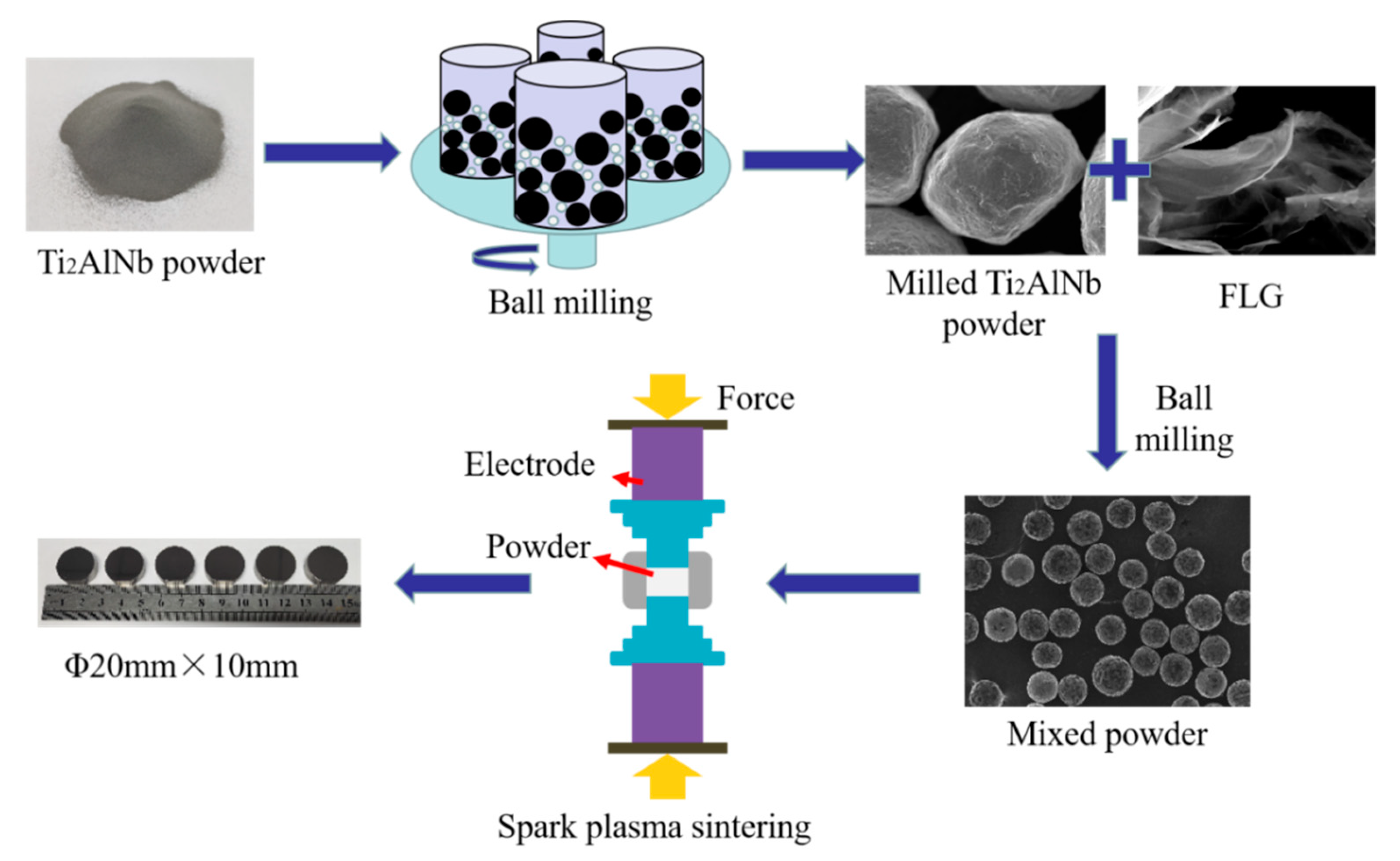
Figure 1. Schematic diagram of the preparation process of the composites.
Metals 10 00924 g001
Figure 2. SEM image of the raw Ti2AlNb pre-alloy powders (a); SEM images of few-layer graphene (FLG) (b); SEM images of TF10 mixed powders (c); XRD patterns of the raw Ti2AlNb pre-alloy powders (d); Raman spectra of FLG (e); EDS of TF10 mixed powder (f).
Metals 10 00924 g002
Figure 3. Characterization of the FLG/Ti2AlNb composites: Macroscopic morphology of the sintered composites (a); SEM image of the sintered composites: TF2 (b); TF6 (c); TF10 (d); BSE image of the sintered composites: TF2 (e); TF6 (f); TF10 (g); XRD patterns of TF2, TF6 and TF10 (h); Micro-area Raman spectra of TF2, TF6 and TF10 (i).
Metals 10 00924 g003
Figure 4. The typical friction coefficient curves of the composites: TF0 (a); TF2 (b); TF4 (c); TF6 (d); TF8 (e); TF10 (f).
Metals 10 00924 g004
Figure 5. Average coefficients of friction (COFs) of the composite materials (a); Wear rates of the composite materials (b).
Metals 10 00924 g005
Figure 6. SEM images of worn surfaces of the composites, TF0 (a); TF2 (b); TF4 (c); TF6 (d); TF8 (e) and TF10 (f).
Metals 10 00924 g006
Figure 7. SEM images of TF6 (a); EDS images of TF6 (b); Raman spectra of TF6 (c); Weight percentages of the elements in the worn surface of TF6 (d).
Metals 10 00924 g007
Figure 8. OM (Optical microscope) images of worn surfaces of the TF0, TF8 and TF10 GCr15 ball (ac); SEM and EDS images of the enlarged TF8 (d); XPS spectra of C elements on the worn surface of TF6 ball (e).
Metals 10 00924 g008
Figure 9. SEM images of the wear debris of TF0-TF10 (ac); SEM and EDS images of the enlarged TF6 (d).
Metals 10 00924 g009
Figure 10. Antifriction mechanism diagram of FLG/Ti2AlNb materials: before the friction (a) after the friction (b).
Metals 10 00924 g010
Table 1. Chemical composition of GCr15 steel.
CSiMnSMoPCrNiCu
0.95–1.050.15–0.350.20–0.400.020≤0.100.0271.30–1.65≤0.30≤0.25
Table 2. Density and densification of FLG/Ti2AlNb composites.
SampleTheoretical Density (g/cm3)Actual Density (g/cm3)Densification (%)Porosity (%)
TF05.2105.09297.742.26
TF25.1975.16899.450.55
TF45.1835.16699.670.33
TF65.1705.15799.750.25
TF85.1575.14699.790.21
TF105.1435.12299.580.42
Table 3. Effects of different additives on wear resistance of the composites.
Composite MaterialsBased AlloyReinforced PhaseContentWear PropertiesAnti-Friction Effect of Average Unit Mass Fraction
Present WorkTi2AlNbFLG
(wt.%)
0Wear Rate
(×10−5 mm3·N−1·m−1)
6.8173.49%
0.25.34
0.44.22
0.64.06
0.84.19
1.03.47
[28]TiTiC
(%)
30Wear Mass Loss
(m/mg)
4.380.07%
402.55
501.5
600.92
[29]Ni-Cr-TiC-BN
(wt.%)
20Wear Mass Loss
(m/mg)
2.352.23%
250.75
300.2
350.5
401.5
[30]Ti-46Al-2Cr-2NbTiB20Wear Rate
(×10−5 mm3·N−1·m−1)
15.32.25%
208.22
401.98
[31]Ti6Al4VTiB+TiC
(%)
0Wear Rate
(×10−5 mm3·N−1·m−1)
6.817.35%
25.34
44.22
64.06
84.19
103.47
Table 4. Ultimate compressive strength of (RT) of TF0-TF10.
SamplesTF0TF2TF4TF6TF8TF10
Ultimate compressive strength1407.701515.381445.371463.131398.681389.93
Enhancement effect-7.1%2.6%3.8%−0.6%−1.2%