Abstract
The fatigue fracture mechanism of a nickel-based single crystal (NBSC) superalloy with recrystallized grains was studied at 550 °C by in situ observation with a scanning electron microscope (SEM) for the first time. Multiple crack initiations associated with recrystallized grain boundaries and carbides were observed. By analysis of the slip traces and crack propagation planes, the operated slip systems were identified to be octahedral for both single crystal substrate and recrystallized grains. Distinct crystallographic fractures dominated, accompanied by recrystallized grain boundary associated crack initiations. This is different from the widely reported solely intergranular cracking at high temperature. Fatigue crack growth rate curves showed evident fluctuation, due to the interaction of fatigue cracks with local microstructures and the crack coalescence mechanism. Both the recrystallized grains and the competition between different slip systems were responsible for the deceleration and acceleration of fatigue microstructurally small crack behavior.
1. Introduction
Nickel-based single crystal (NBSC) superalloys have been widely used as high temperature materials in aircraft turbines as well as in land-based gas turbines [1], due to its excellent mechanical properties under high temperature. For NBSC superalloys, since the grain boundaries have been removed, grain boundary strengthening elements, such as Hafnium, and Boron, etc. have been removed or greatly reduced to increase the melting temperature of the superalloy [2,3]. Hence, it makes single crystal superalloy susceptible to transverse grain boundaries, for instance recrystallization (RX) [2,3]. Generally, recrystallization is formed in nickel-based single crystal superalloy due to plastic deformation and subsequent exposure to high temperature [2,3]. In the turbine industry, there have been some reports on recrystallization-induced turbine blade accidents in China and other countries [4,5,6,7]. It is generally accepted that recrystallized grains may act as potential crack initiation sites and hence would be harmful to the fatigue properties of single crystal superalloys. However, little research has been found in open literature regarding the effect of RX on the fatigue behavior of NBSC superalloy [8] or directionally solidified (DS) alloys [9,10,11].
Among the limited studies on the fatigue issues of recrystallization, some essential questions have not yet been addressed. For instance, the primary influence factors for the fatigue fracture mechanism of recrystallized NBSC superalloy are still unclear. The conditions which determine if the partial recrystallization grains are fatal or insignificant to fatigue performance remain unknown, to the author’s knowledge. Bürgel et al. [8] performed fatigue tests on recrystallized single crystal superalloy at 950 °C, suggesting the insignificant influence of recrystallization on crack initiation life, although the recrystallized sample showed higher crack density. Previous studies on partially recrystallized NBSC superalloy also suggested that 150 μm recrystallization layers could remarkably reduce the low cycle fatigue life at 550 °C [2]. Meng J et al. [5] and Zhang B et al. [7] reported that the recrystallized grains would lead to a remarkable decrease in creep life, due to the early cracking of recrystallized grain boundaries perpendicular to the loading direction. Xie G et al. [6] studied the characteristics of recrystallized grain boundaries in the creep crack initiation behavior of a directionally solidified Ni-base superalloy. The recent studies on directionally solidified DZ4 superalloy indicated that the influence of recrystallization was closely related to the microstructure of recrystallized grains. It may evidently decrease the fatigue life of DZ4 [10,12] or even increase the fatigue life by a dense recrystallized layer composed of refined grains [13]. Zhao Y et al. [11] reported that the effect of recrystallized grains led to an evident decrease in fatigue life in directionally solidified superalloy DZ40M. They suggested the effects of the cracking of recrystallized grain boundaries and twin boundaries on fatigue life. Jia B et al. [12] studied directionally Solidified DZ4 superalloy with different recrystallized layer thicknesses by shot peening and annealing, suggesting that thicker recrystallized layer leads to a larger drop in fatigue life. There are quite limited studies on the fatigue failure mechanism of partially recrystallized single crystal superalloys. The noteworthy research of Sehitoglu H. on single crystals using an in situ technique [14,15] provides good insights into the deformation and slip activities associated with fatigue crack advance. Besides, recent studies [9] have indicated that temperature played an important role in altering the fatigue fracture mode of recrystallization. Nevertheless, the effects of temperature have not yet brought conclusive results. Besides, the authors are unaware of any in situ studies on fatigue crack growth (FCG) in the RX layer of single crystal superalloy. Sehitoglu H. [16] has studied the difference between single crystal and polycrystalline Haynes 230 alloy in terms of tensile curves, slip activity, and local plastic deformation accumulation occurring in the grains and along grain boundaries, which can shed lights on the recrystallization issue. Understanding of fatigue crack initiation and propagation behavior in RX layer can be crucial for the safety evaluation of turbine blades with recrystallization issues.
In this work, the fatigue deformation and fracture behavior of a nickel-based single crystal superalloy with recrystallized grains were studied at 550 °C by in situ SEM. The real time observations were used to identify the operated slip systems and the shear stress responsible for growing fatigue crack tip. The effects of recrystallized grains and the competition between different slip systems on fatigue small crack growth behavior were analyzed based on in situ studies. The underlying mechanism for the variation of crack path and small crack growth rates was discussed accordingly.
2. Material and Experimental
The material used in this study was a nickel-based single crystal superalloy, which was developed for fabricating high-performance gas-turbine blades [17]. The nominal composition of this NBSC alloy is (in wt.%): 0.067 C, 3.9 W, 12.0 Cr, 9.0 Co, 3.6 Al, 5.0 Ta and the remainder is Ni. The slab specimen had a dog-bone shape with a 2.5 mm by 0.4 mm gauge cross section, as shown in Figure 1. In the present experimental study, the specimen/loading axis is along [011], with the transverse orientation (crack growth direction) along [100], as shown in Figure 2. It is known that multiple octahedral slip systems, i.e., {111} <110>, can be activated in the NBSC alloy. Figure 4 shows the duplex octahedral slip planes and the corresponding slip directions, respectively.
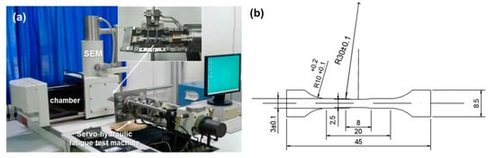
Figure 1.
Fatigue test setup and specimen: (a) In situ SEM fatigue testing facility; (b) Fatigue test specimen geometry (dimensions in mm).
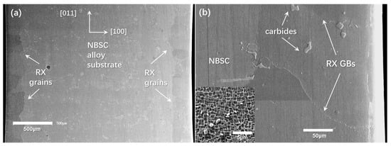
Figure 2.
Single crystal superalloy with surface recrystallized grains: (a) top view showing recrystallized layer of 200 μm thickness; (b) recrystallized grain boundaries and carbides (the insert is high magnification of the γ/γ’ microstructure of single crystal superalloy).
The specimen was subjected to shot peening (0.5 MPa, 20 min) on the later edge to introduce plastic deformation. A solution heat treatment was performed at 1220 °C for 4 h, followed by air cooling. To prevent oxidization, the specimens were enclosed in a quartz cuvette and slight argon gas was maintained. It has also been used in the previous studies of recrystallized DZ4 alloy [13].
The fatigue specimen was grinded and polished following general procedure until it was a 1 μm diamond paste. To reveal the prevailing microstructure for in situ observations, the specimen was etched in an aqueous solution of 4 g CuSO4 + 20 mL HCl + 20 mL H2O prior to fatigue tests. No effect of the etching on the crack path was found. The fatigue crack propagation tests were performed in the vacuum chamber of the SEM using a specially designed servo-hydraulic testing system (Shimadzu, Kyoto, Japan). This machine provided pulsating (sinusoidal wave) loads at 10 Hz of ±1 kN maximum capacity and a displacement range of ±25 mm. The signal of the SEM was directly transferred to a computer via a direct memory access type A/D converter, making it possible to sample 960 × 1280 frames of SEM images successively. The SEM was operated at secondary electronic mode with an accelerating voltage of 15 kV.
A constant maximal stress of 750 MPa was adopted throughout the test to study the fatigue crack propagation process at 550 °C. The selected temperature of the local region of the turbine blade where recrystallized grains were found was 550 °C. The waveform utilized was sinusoidal. All fatigue tests were load controlled at a stress ratio of 0.1 with a loading frequency of 2 Hz. Three samples were tested for the present temperature and stress. Images of fatigue crack with different lengths were taken in situ at different cycles of loading and hence the crack growth rate can be calculated from the measured crack lengths. By comparing with the propagation process, the dependence on the local structures and cracking manner can be analyzed and disclosed.
3. In Situ Observation Results
3.1. Fatigue Crack Initiation Mechanism
Figure 3a shows that duplex slip traces were formed in the nickel-based single crystal superalloy substrate, with the loading axis along the vertical direction. The slip traces were measured to be about 35°, inclined with respect to the loading direction. It was due to the fact that two octahedral slip systems have the same value of maximal Schmid factor, as shown in Figure 4. The dominated slips occurred on the two octahedral planes, i.e., () and (111), by searching all possible slip systems, either octahedral or cube. In Figure 3b, the slip traces interacted with recrystallized grains; however, they failed to enter the recrystallized grains, showing the blocking effect of recrystallized grain boundaries (GBs). After another hundred loading cycles, a crack was noticed at the NBSC/RX interface in Figure 3c, due to the impingement of slip bands against the recrystallized GBs. The intrusion and extrusion formed at the recrystallized GB would finally evolve into a micro-crack along the GB. This phenomenon has been well described in other metals by Zhang Z.F. et al. [18]. Aside from the cracking of the NBSC/RX interface, cracks were also formed at the horizontal recrystallized GB, as shown in Figure 3d, due to the deformation mismatch of adjacent grains with different crystal orientation. Besides, the blocky carbides located at the recrystallized grain boundaries were primary crack initiators due to the stress concentration and the brittleness of carbides. It is favorable for the trend of multiple crack initiation sites [2,3]. Figure 3e,f show two typical examples, which are similar to those reported in the fatigue fracture of the recrystallized directionally solidified DZ4 superalloy. Crystal plasticity finite element simulation studies [19] also indicated that the modulus, strength, and shape of carbides, and grain orientations would affect the maximal cyclic plastic strain occurring in the neighborhood of carbide and thus promote the fracture of carbide, leading to earlier crack initiation.
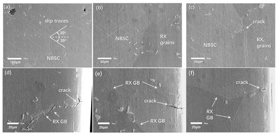
Figure 3.
Fatigue deformation and crack initiation features: (a) duplex slip traces in single crystal substrate; (b) RX grains free of slip traces; (c) crack initiation at the interface between RX grains and single crystal substrate; (d) crack initiation at recrystallized grain boundary; (e,f) crack initiation by fracture of carbides at recrystallized grain boundary. (The loading direction is vertical.)
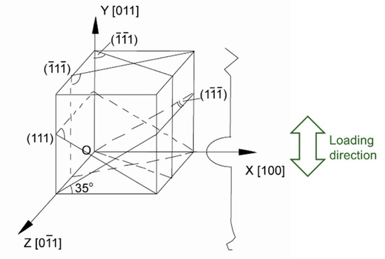
Figure 4.
Crystallographic representation and slip systems of nickel-based single crystal superalloy with loading along [011] orientation.
3.2. Fatigue Crack Propagation Behavior
In spite of multiple crack initiations in the recrystallized layer, most of the cracks appeared to be non-propagating or propagate at extremely slow growth rate in the whole period of fatigue life. Two propagating cracks of importance were identified. The propagation behavior was carefully examined to show the fatigue cracking features and to understand the underlying fracture mechanism.
Figure 5 depicts the evolution of the fatigue crack shown in Figure 3e. It is evident that, although the crack nucleation was caused by the carbide at the grain boundary, the subsequent propagation followed an evidently transgranular cracking manner, via the crystallographic slip mechanism, which was different from the widely reported intergranular fracture. Single slip trace was observed in the recrystallized grain, which was related to the grain orientation. The crystallographic crack appeared sharp with small crack opening displacement (COD), due to its shearing dominated nature, as shown in Figure 5d,e. While the crack approached the interface between RX and single crystal substrate, a secondary crack emerged following the same shearing direction, as shown in Figure 5e,f. The secondary crack was also associated with the carbide at the RX/NBSC interface. In the following loading cycles, the crack did not evolve into a primary crack.
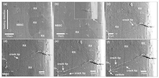
Figure 5.
Fatigue crack initiation and propagation at surface recrystallized grains of nickel-based single crystal superalloy: (a) 0 cycle; (b) 392 cycles; (c) 31,036 cycles; (d) 62,956 cycles; (e) 115,004 cycles; (f) 126,276 cycles.
The corresponding fatigue crack growth rate (FCGR) was by the slope (da/dN) of crack length increment per cycle, given by:
(da/dN)i = (ai+1 − ai)/(Ni+1 − Ni)
The stress intensity factor (SIF) range for a single edge crack plate of finite width is given by:
where Δσ is the stress range, a is the crack length defined as the projected length vertical to the loading axis, and is the width of the specimen. Let ξ = a/W, the function of F(ξ) (ξ = a/W) is defined as in [20].
As adopted in many studies, the crack growth rate (da/dN) was plotted against the stress intensity range (ΔK), as first proposed by Paris and Erdogan [21]. The fatigue crack growth rate curve is shown in Figure 6. The initial propagation of fatigue crack was fast at “b” and showed deceleration afterwards. The fatigue crack propagated at a slow rate, until an evident crystallographic crack tip was formed, shown in Figure 5c. The crack propagated obviously along the crystallographic plane in the next thousand cycles, shown in Figure 5c–e, at a relatively stable propagation rate, as shown in Figure 5d–e. Afterwards, as shown in Figure 5f, a secondary crack nucleating from the carbide at recrystallized GB was formed, following the same direction as the prior crack. In the remaining fatigue life cycles, these two fatigue cracks did not merge with each other and the fatigue cracks were almost non-propagating, or the propagation was negligible, as shown in Figure 5f.
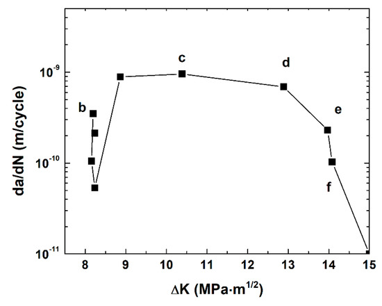
Figure 6.
Fatigue crack growth rate of Crack-1 in recrystallized nickel-based single crystal superalloy.
Figure 7 shows the propagation behavior of the primary fatigue crack, which is responsible for the final fracture of the fatigue sample. Figure 7b–j correspond to “b” to “j” in the fatigue crack growth rate curve of primary crack in Figure 8. In Figure 7a, fatigue crack initiated at the RX grain boundary, due to the strain mismatch caused by different orientations of adjacent grains [19]. Of interest is that the following crack propagation exhibited transgranular mode, which was distinct from the previously reported intergranular fracture. Fatigue crack extended into both grains via crystallographic mode, as shown in Figure 7b. In Figure 7c, the primary crack tip “T1” was arrested and a secondary crack “T2” was formed. It is inferred that duplex slip systems can be preferably activated in the RX grain, similar to the [011] oriented single crystal substrate. The fatigue crack “T2” was also arrested, shown in Figure 7d, corresponding to a small FCGR marked as “d” in the FCGR curve in Figure 8. A crack, “T3”, was initiated from another RX GB, as shown in the inserted micrograph of Figure 7d. Crack “T4” was formed with a direction parallel to Crack “T1”. Crack “T2” become non-propagating for a long time until coalescence with Crack “T4”, as shown in Figure 7e, which leads to remarkable increase in the primary crack length. It corresponds to a peak of FCGR, marked as “e” in the FCGR curve in Figure 8. A high magnification examination showed that the primary crack tip penetrated the RX/NBSC interface. In Figure 7f,g, the primary crack showed an evident increase in crack opening displacement and out of plane displacement. It is associated with the fact: (i) the primary crack is long enough to provide a higher ∆K and a larger COD; (ii) the NBSC substrate has different activated slip orientations, causing a deceleration of crack propagation in the substrate, corresponding to “g” in the FCGR curve in Figure 8. Figure 7h show the high magnification examination of the primary crack tip in the NBSC substrate, revealing that the crack move forward again, depicted by “h” in Figure 8. The fatigue crack was overall along the horizontal, but microscopically following a zig-zag mode via operation of duplex slip systems in Figure 4. In Figure 7i, the fatigue crack was shifted to another octahedral slip plane, which decreased the FCGR, marked as “i” in Figure 8. The slip bands become denser compared with that in Figure 7f, and the COD was remarkably large, with the crack mating surfaces partly contacted with each other, as arrowed in Figure 7f. As shown in Figure 7j, the crack propagation came back to the zig-zag cracking mode via duplex slip systems, as marked by the dashed lines “C3”. For the carbides perpendicular to slip bands “C2”, the interaction of slip bands against carbide led to the opening of the interface and a crack was formed.
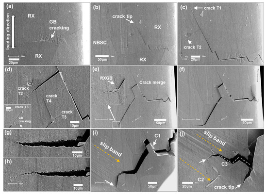
Figure 7.
Fatigue propagation behavior of recrystallized single crystal superalloy: (a) 115,004 cycles; (b) 125,316 cycles; (c) 137,266 cycles; (d) 149,841 cycles; (e) 152,223 cycles; (f) 157,161 cycles; (g)158,531 cycles; (h) 159,858 cycles; (i) 162,326 cycles; (j) 163,571 cycles.
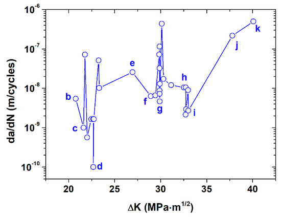
Figure 8.
Fatigue crack growth rate curves of the primary crack (da/dN in terms of ∆K).
Figure 9 shows the fatigue crack features before the final rupture of the recrystallized single crystal superalloy in Figure 7. The slip bands in the NBSC substrate became more intense and the cracking of the carbide/NBSC interface (“C4”) was more evident than that of Figure 7j. The zig-zag cracking (“C5”) was quite pronounced, following () and (111), alternatively. River patterns were clearly observed on the fractured crystallographic plane “C6”, indicating cleavage fracture along a slip plane. The octahedral plane was identified to be (), according to the configuration in Figure 4, by searching all possible octahedral slip systems.
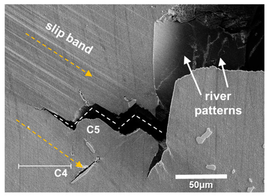
Figure 9.
Fatigue crack features before final rupture of recrystallized single crystal superalloy.
4. Discussion
4.1. Effect of Temperature
It is revealed from the above in situ observations that octahedral slip induced cracking is the dominant fatigue fracture mode in the present study. This failure mode was also reported in the PWA1480 superalloy by Telesman et al. [22]. This supports that, at low or intermediate temperatures, the crack growth of NBSC superalloy would occur either on a single octahedral slip plane or on several octahedral slip planes, resulting in crystallographic {111} facets on the fracture surface [17]. Different octahedral slip systems may be operated, controlled by both crystal orientation and test conditions [23,24]. The fatigue failure on specified slip planes is known to be governed by the resolved shear stress, instead of the maximum principle stresses in conventional polycrystalline materials. The dominated deformation mechanism is the shearing of γ/γ’ at this temperature, as observed in the studies of low cycle fatigued NBSC specimens at 600 °C [17].
The author’s previous studies [2] indicated that intergranular cracks were just occasionally observed, and crystallographic cracking was dominant for fatigue failure of recrystallized NBSC superalloy at 550 °C. At higher temperature, for instance at 850 °C [25], intergranular fracture along recrystallized grain boundaries would be preferred. Figure 10 shows the longitudinal section microstructure of recrystallized NBSC superalloy after conventional strain-controlled fatigue testing at 850 °C. Both oxidation-assisted grain boundary degradation and strength decrease in the grain boundary would lead to intergranular cracking [25]. For this study at 550 °C in vacuum, it is evidently revealed that the recrystallized grain boundary and the associated carbides played an important role in the fatigue crack initiation process. The subsequent crack propagation was overall dominated by crystallographic cracking via one or multiple slip systems. It is expected that, at higher temperature, intergranular cracking will play a more and more important role in the failure analysis of recrystallized single crystal superalloys.
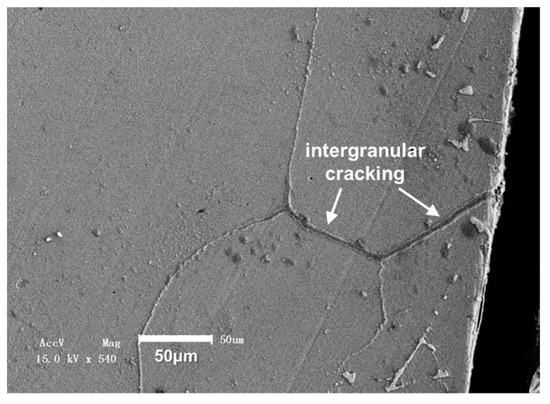
Figure 10.
Intergranular cracks observed in the recrystallized single crystal superalloy after fatigue testing at 850 °C [25].
4.2. Microstructurally Small Crack Behavior
In the above in situ observations, the fatigue crack growth behavior in Figure 5 and Figure 7 show evident dependence on the microstructure of recrystallized grains and NBSC substrate. First of all, for the original NBSC superalloy, casting porosity has been reported to be the primary crack initiation site [2,17]. In contrast, for the recrystallized NBSC superalloy, it showed evident multiple crack initiation related to recrystallized GBs and carbides. Hence, the recrystallized grain orientation, misorientation, and carbide property would affect the fatigue crack initiation process.
For the small crack growth behavior within the recrystallized grains, the fatigue crack paths were strongly dependent on the local recrystallized grain orientation, as shown in both Figure 5 and Figure 7. Especially in Figure 7, the fatigue crack path showed an evident bifurcation phenomenon and secondary cracking, which was closely related to the cracking of recrystallized GBs and the blocking effect of the RX/NBSC interface. This process is essentially affected by the local cyclic plastic strain distribution within the recrystallized grains, as indicated by crystal plasticity finite element simulation [19].
Referring to Figure 6 and Figure 8, both FCGR curves showed remarkable fluctuations, which is indicative of microstructural fatigue and small crack behavior. The deceleration of FCGR was usually related to the blocking of the recrystallized GBs or interfaces. While the crack came across the RX/NBSC interface, different slip planes in the NBSC substrate also led to the temporary arrest of small crack growth. Even when the fatigue crack propagated in the [011] substrate, there was competition between different octahedral slip systems, as shown in Figure 7 and Figure 9. The alternate operation of duplex slip planes, i.e., () and (111), were commonly observed, following secondary cracking in Figure 7c, or zig-zag cracking mode in Figure 7g,j. According to Telesman et al. [22], the slip systems with high resolved shear stress intensity are preferential to be operated during cyclic loading. When the operated slip system was not efficient in extending the fatigue crack length, as shown in Figure 7i, the fatigue crack would return to propagate along the duplex slip planes soon, as shown in Figure 7j. For the acceleration of FCGR in this study, it was usually related to the overcoming of microstructural barriers, such as recrystallized GBs or interfaces, as shown in Figure 7b,f. Another important mechanism of accelerated crack growth is via the coalescence of primary cracks with the secondary cracks, as shown in Figure 7e.
5. Conclusions
The fatigue fracture behavior of nickel-based single crystal superalloy with surface recrystallized grains was studied at 550 °C by in situ SEM investigations. The following conclusions were obtained:
- (1)
- Multiple crack initiation was observed at the recrystallized grain boundaries, either by intergranular cracking of grain boundaries, or by the fracture of carbides at the grain boundaries.
- (2)
- The operated slip systems for both the nickel-based single crystal superalloy and the recrystallized grains were identified to be octahedral slips, by analysis of surface slip trace and crystallographic configuration.
- (3)
- The recrystallized nickel-based single crystal superalloy showed distinct fatigue fracture mechanisms at 550 °C. Crystallographic slip deformation is responsible for all fatigue cracks in the present study. The intergranular cracking of the recrystallized grain boundary was due to the impingement of intensive slip bands against the grain boundary. The subsequent fatigue crack propagation was dominated by transgranular cracking manner. At high temperature, commonly reported intergranular cracking would be expected.
- (4)
- Fatigue crack propagation exhibited microstructural small crack behavior. Local microstructural inhomogeneities, such as recrystallized grain boundaries or interfaces, were found to expressly alter the propagation path as well as the crack growth rate. Besides, the competition between different slip systems and the crack coalescence mechanisms were another two important factors responsible for the evident fluctuation in fatigue crack growth rate curve.
Author Contributions
Conceptualization, X.M. and H.-j.S.; Data curation, H.Y., J.T. and H.Z.; Formal analysis, H.Y., J.J., Z.W., X.M., J.T., H.Z. and W.Z.; Investigation, H.Y., X.M., H.-j.S. and W.Z.; Methodology, J.J., Z.W., X.M. and W.Z.; Resources, X.M., H.-j.S.; Supervision, H.-j.S.; Validation, X.M. and J.J.; Writing—original draft, H.Y. and X.M.; Writing—review and editing, X.M. All authors have read and agreed to the published version of the manuscript.
Funding
This research was funded by National Natural Science Foundation of China (No. 11902370), Guangdong Project of Basic and Applied Basic Research (No. 2019B030302011, 2019A050510022, 2019B010943001, 2017B020235001), China Postdoctoral Science Foundation (No. 2019M653173 and 2019TQ0374), Guangdong Education Department Fund (No. 2016KQNCX005), and Fundamental Research Funds for the Central Universities (No. 19lgpy304).
Acknowledgments
This project is supported by the National Science Foundation of China (No. 11902370), Guangdong Major Project of Basic and Applied Basic Research (2019B030302011), International Sci and Tech Cooperation Program of GuangDong Province (2019A050510022), Key-Area Research and Development Program of GuangDong Province (2019B010943001), Guangdong Provincial Basic and Applied Basic Research (2017B020235001), China Postdoctoral Science Foundation (2019M653173 and 2019TQ0374), Guangdong Education Department Fund (2016KQNCX005), and Fundamental Research Funds for the Central Universities (19lgpy304).
Conflicts of Interest
The authors declare no conflict of interest.
References
- Joyce, M.R.; Wu, X.; Reed, P.A.S. The effect of environment and orientation on fatigue crack growth behaviour of CMSX-4 nickel base single crystal at 650 °C. Mater. Lett. 2004, 58, 99–103. [Google Scholar] [CrossRef]
- Ma, X.; Shi, H.J.; Gu, J.L.; Yang, Z.; Chen, G.F.; Luesebrink, O.; Harders, H. Influence of surface recrystallization on the low cycle fatigue behavior of a single crystal superalloy. Fatigue Fract. Eng. Mater. 2015, 38, 340–351. [Google Scholar] [CrossRef]
- He, Y.H.; Hou, X.Q.; Tao, C.H.; Han, F.K. Recrystallization and fatigue fracture of single crystal turbine blades. Eng. Fail. Anal. 2011, 18, 944–949. [Google Scholar] [CrossRef]
- Li, Z.; Xu, Q.; Liu, B. Experimental investigation on recrystallization mechanism of a Ni-base single crystal superalloy. J. Alloy. Compd. 2016, 672, 457–469. [Google Scholar] [CrossRef]
- Meng, J.; Jin, T.; Sun, X.; Hu, Z. Effect of surface recrystallization on the creep rupture properties of a nickel-base single crystal superalloy. Mater. Sci. Eng. A 2010, 527, 6119–6122. [Google Scholar] [CrossRef]
- Xie, G.; Lou, L.H. Influence of the characteristic of recrystallization grain boundary on the formation of creep cracks in a directionally solidified Ni-base superalloy. Mater. Sci. Eng. A 2012, 532, 579–584. [Google Scholar] [CrossRef]
- Zhang, B.; Lu, X.; Liu, D.L.; Tao, C.H. Influence of recrystallization on high-temperature stress rupture property and fracture behavior of single crystal superalloy. Mater. Sci. Eng. A 2012, 551, 149–153. [Google Scholar] [CrossRef]
- Bürgel, R.; Portella, P.D.; Preuhs, J. Recrystallization in Single Crystals of Nickel Base Superalloys. In Superalloys 2000; Pollock, T.M., Kissinger, R.D., Bowman, R.R., Eds.; TMS: Warrendale, PA, USA, 2000; pp. 229–238. [Google Scholar]
- Ma, X.F.; Shi, H.J.; Gu, J.L. In-situ scanning electron microscopy studies of small fatigue crack growth in recrystallized layer of a directionally solidified superalloy. Mater. Lett. 2010, 64, 2080–2083. [Google Scholar] [CrossRef]
- Shi, H.J.; Zhang, H.F.; Wu, Y.Q. Effect of recrystallization on low-cycle fatigue behavior of DZ4 directionally-solidified superalloy. Key Eng. Mater. 2006, 306–308, 175–180. [Google Scholar] [CrossRef]
- Zhao, Y.; Wang, L.; Li, H.Y.; Yu, T.; Liu, Y. Effects of recrystallization on the low cycle fatigue behavior of directionally solidified superalloy DZ40M. Rare Met. 2008, 27, 425–428. [Google Scholar] [CrossRef]
- Jia, B.; Li, C.G.; Li, H.Y. Influence of Recrystallization Layer at Surface on Fatigue Behaviors of Directionally Solidified DZ4 Superalloy. Mater. Eng. 2008, 6, 64–71. [Google Scholar]
- Ma, X.; Shi, H.J. In situ SEM studies of the low cycle fatigue behavior of DZ4 superalloy at elevated temperature: Effect of partial recrystallization. Int. J. Fatigue 2014, 61, 255–263. [Google Scholar] [CrossRef]
- Rabbolini, S.; Luccarelli, P.G.; Beretta, S.; Foletti, S.; Sehitoglu, H. Near-tip closure and cyclic plasticity in Ni-based single crystals. Int. J. Fatigue 2016, 89, 53–65. [Google Scholar] [CrossRef]
- Rabbolini, S.; Pataky, G.J.; Sehitoglu, H.; Beretta, S. Fatigue crack growth in Haynes 230 single crystals: An analysis with digital image correlation. Fatigue Fract. Eng. Mater. 2015, 38, 583–596. [Google Scholar] [CrossRef]
- Luccarelli, P.G.; Pataky, G.J.; Sehitoglu, H.; Foletti, S. Finite element simulation of single crystal and polycrystalline Haynes 230 specimens. Int. J. Solids Struct. 2017, 115, 270–278. [Google Scholar] [CrossRef]
- Ma, X.F.; Shi, H.J.; Gu, J.L.; Wang, Z.X.; Harders, H.; Malow, T. Temperature effect on low-cycle fatigue behavior of nickel-based single crystalline superalloy. Acta Mech. Solida Sin. 2008, 21, 289–297. [Google Scholar] [CrossRef]
- Zhang, Z.F.; Wang, Z.G. Dependence of intergranular fatigue cracking on the interactions of persistent slip bands with grain boundaries. Acta Mater. 2003, 51, 347–364. [Google Scholar] [CrossRef]
- Ma, X.; Wei, D.; Han, Q.; Rui, S. Parametric study of cyclic plasticity behavior in a directionally solidified superalloy with partial recrystallization by crystal plasticity finite element simulation. J. Mater. Eng. Perform. 2019. [Google Scholar] [CrossRef]
- Wang, X.S.; Fan, J.H. An evaluation on the growth rate of small fatigue cracks in cast AM50 magnesium alloy at different temperatures in vacuum conditions. Int. J. Fatigue 2006, 28, 79–86. [Google Scholar] [CrossRef]
- Paris, P.; Erdogan, F. A critical analysis of crack propagation laws. J. Basic Eng. Dec. 1963, 85, 528–533. [Google Scholar] [CrossRef]
- Telesman, J.; Ghosn, L.J. Fatigue crack growth behavior of PWA 1484 single crystal superalloy at elevated temperatures. J. Eng. Gas Turbines Power 1996, 118, 399–405. [Google Scholar] [CrossRef]
- Henderson, M.B.; Martin, J.W. The influence of crystal orientation on the high temperature fatigue crack growth of a Ni-based single crystal superalloy. Acta Mater. 1996, 44, 111–126. [Google Scholar] [CrossRef]
- Suresh, S. Fatigue of Materials, 2nd ed.; Cambridge University Press: New York, NY, USA, 1998. [Google Scholar]
- Ma, X.; Jiang, J.S.; Zhang, W.J.; Shi, H.J.; Gu, J.L. Effect of Local Recrystallized Grains on the Low Cycle Fatigue Behavior of a Nickel-Based Single Crystal Superalloy. Crystals 2019, 9, 312. [Google Scholar] [CrossRef]


© 2020 by the authors. Licensee MDPI, Basel, Switzerland. This article is an open access article distributed under the terms and conditions of the Creative Commons Attribution (CC BY) license (http://creativecommons.org/licenses/by/4.0/).