Abstract
This study compared the mechanical properties of the NAB (Ni-Al-bronze) material fabricated using wire arc additive manufacturing (WAAM) technology with those of the cast NAB. Using a CMT (cold metal transfer) welding process, this study analyzed the bead shape for six welding conditions, determined an appropriate bead shape, and fabricated a square bulk NAB material using the bead shape. For a mechanical properties comparison, the study obtained two test specimens per welding direction from the fabricated bulk NAB material, and compared those with the cast NAB materials. In the tensile test, the deposited NAB material showed significantly better results than the cast NAB; furthermore, the deposited NAB material showed better performance than the cast NAB material in the Vickers hardness test, impact test and wear test. In addition, the deposited NAB showed anisotropy depending on the welding direction, and showed high tensile strength, hardness and shock absorption in the longitudinal direction of the welding line.
1. Introduction
WAAM (wire arc additive manufacturing) is one of the three-dimensional metal printing technologies that uses arc heat sources to melt metal wires in making shapes [1]. The American Society for Testing and Materials (ASTM) classifies three-dimensional deposition methods into seven types, regardless of the material [2]. Of these, dual metal based additive manufacturing technology is categorized into four types according to the heat source, processing method, etc. The most dominant technologies are the powder bed fusion (PBF) method that shoots a laser on metal powder, and direct energy deposition (DED) that supplies materials to a direct heat source. WAAM technology falls under the DED category as classified by ASTM, and employs gas metal arc welding (GMAW) and gas tungsten arc welding (GTAW) processes that use arc heat sources. This added the deposition technique to the existing welding process, and was also called a metal rapid porotype or metal cladding process. It appeared with the name of WAAM as the 3D metal deposition industry market expanded.
In powder-type metal deposition, which has been studied a significant amount to date, the surface shape is very smooth because the fine powders of 50 μm~150 μm are deposited through a laser heat source, but the amount of metal deposited is 5 g/min~10 g/min, making it difficult to fabricate large parts [3]. Meanwhile, WAAM uses off-the-shelf 1.2 Ø~2.4 Ø welding wires and supplies the wire at a rate of about 5 m/min for deposition, so it has the advantage of being able to deposit large parts in a short time. In addition, although the precision of parts is low, it uses a wire that costs only 1/2~1/3 the cost of the metal powder for DED, and does not require the use of expensive laser power sources. WAAM technology is advantageous for fabricating large parts with complex shapes that are difficult to fabricate using conventional metal powder deposition technology, and has been recognized as an alternative to the general casting method or methods that have a large material loss caused by cutting. In recent years, WAAM technology has been becoming popular at industrial sites, and studies on metal deposition using existing commercial welding technology have been ongoing [4,5,6,7,8,9].
In WAAM technology, the deposition wires are mostly based on welding wires. There have been studies on the deposition of parts using commercial welding wire. In addition, because WAAM is used to minimize the bulk material loss caused by commercial cutting technologies, there have been studies on high cost materials such as Ti alloy [10,11,12,13], high-nickel alloy [14,15], magnesium alloy [16,17], managing steel [18], etc. rather than the low-cost steels.
Recently, the materials for WAAM have been expanded to include bronze alloys, brass alloys, etc. The Ni-Al-bronze (NAB) alloy has a low corrosion rate and high cavitation resistance in a seawater environment, so it is often used as a material to fabricate marine propellers, seawater pump impellers, valves, and underwater fasteners [19]. Ni-Al-bronze (NAB) alloy is a material that is used to fabricate marine impellers because of its excellent yield strength, tensile strength, and endurance in seawater compared to the manganese bronze alloys that have been commonly used [20]. Lv et al. [21] stretched the cast NAB alloy to observe the corrosion state and residual stress in a seawater environment, and reported that the stress generated in the seawater environment improved the resistance to the corrosion environment. Ship propellers have a very complex shape and are made by assembling separately fabricated shafts and blades with a diameter of more than 10 m, or by investing a lot of time and cost through sand casting [22]. If a complex part is fabricated by casting, differences in casting structure may occur depending on thickness and location. Hazra et al. [23] reported that damage to the NAB impeller fabricated by casting may be caused by the difference in compound composition and cooling speed in the casting environment. Zhao et al. [24] explained, through a histological analysis, that differences in mechanical properties occur depending on the location of the NAB material fabricated by casting due to processing hardening and grain refinement after machining. Attempts have been made to fabricate parts by applying WAAM technology to overcome the non-uniformity and productivity, etc. of the physical properties of NAB materials fabricated by casting.
Li et al. [25] evaluated the corrosion properties by reinforcing the surface of cast NAB material using a FSW (friction stir welding) process, and reported that the corrosion performance was improved by 41% compared to the cast NAB. Dharmendra et al. [26,27] attempted to identify interfacial characterization, prospects and problems by laminating NAB material on STS 316L substrate, and explained the cause of liquation cracking in the HAZ (heat affect zone) section. Chen Shen [28] used GMAW to fabricate parts used in the actual marine industry and reported metallurgical differences according to post-heat treatment conditions. A range of studies have been conducted, and it is necessary to compare the mechanical properties of the cast NAB material and the NAB material fabricated by WAAM to expand the applicability of NAB alloy to WAAM.
This study conducted an ASTM B 150 (NAB) alloy deposition experiment using WAAM, and analyzed the shape of a single bead according to welding conditions and the mechanical properties (tensile, yield, elongation, hardness, impact, wear) of the cast NAB material and the NAB material fabricated by WAAM.
2. Experiment Method
2.1. Experiment Preparation
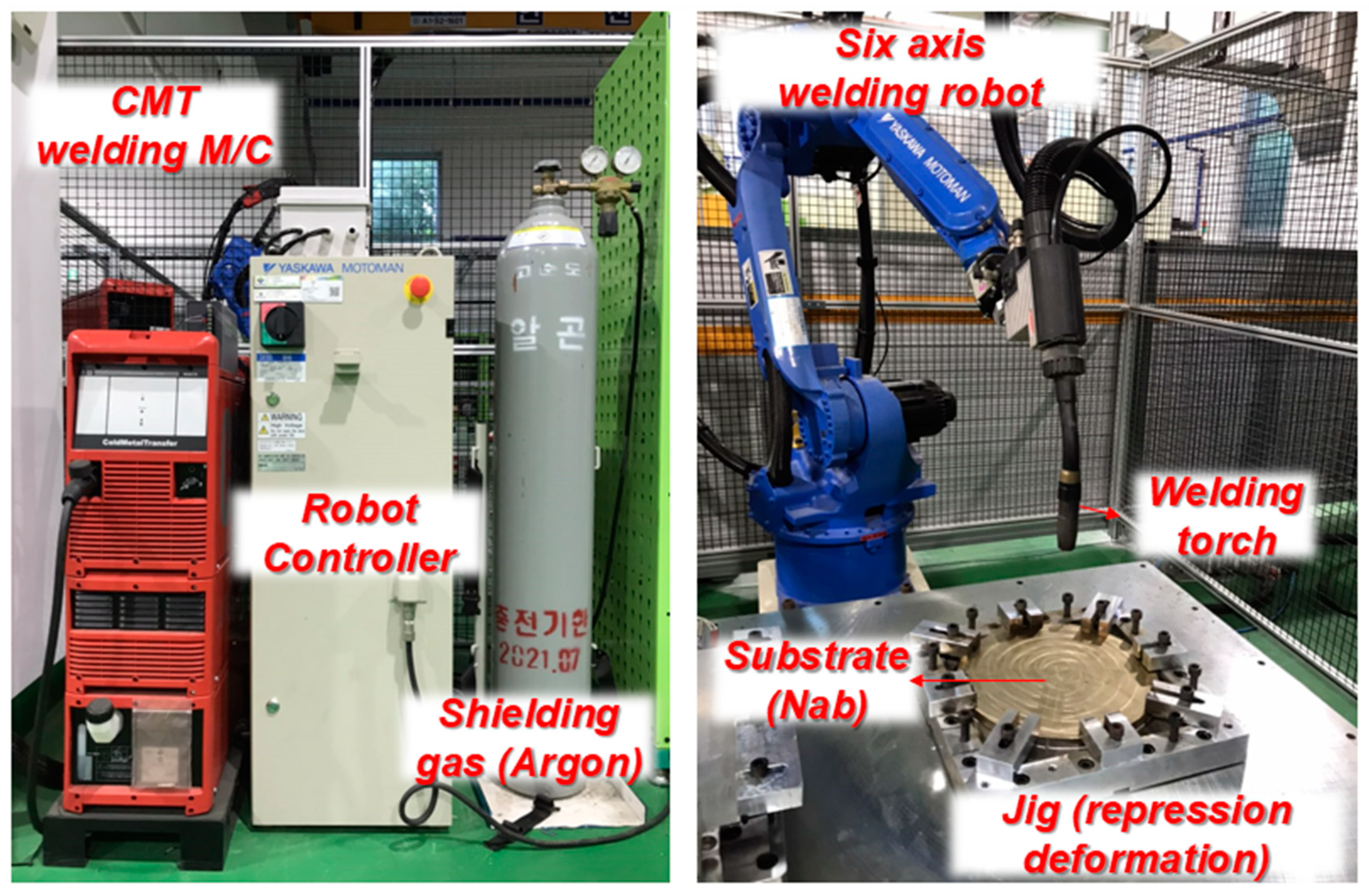
In general, the WAAM system uses a robotic system to maximize the degrees of freedom in part shape. The combination of the robot system, CAD (computer aided design) and CAM (computer aided manufacturing) allows the optimization of stacking order and deposition path. Figure 1 shows the combination of the robot system and MIG (metal inert gas) welding machine used in the welding experiment. A Fronius CMT (cold metal transfer) welding machine was used and a Motorman HP20D six-axis robot (Yaskawa, Kitakyushu, Japan) was employed as the motion provisioning unit. The accuracy of the motion system was 0.06 mm.
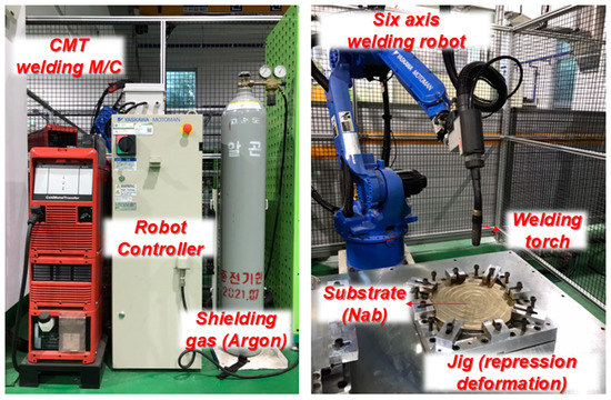
Figure 1.
Wire arc additive manufacturing (WAAM) system configuration adopted in the experiment.
The jig used in the welding experiment was designed to clamp at 8 points to minimize the deformation of the substrate (cast NAB alloy). When fabricating a part using WAAM, the deformation of the substrate is severe due to the long welding time and continuous heat input. For this reason, a jig that can suppress deformation is essential because the deformation may cause deviation from the deposition path. The substrate was made of cast NAB (CAC703C) round rod material of 250 mm (D) × 25 mm (T), and America welding society (AWS) 5.1 certified 1.2 mm diameter ERCuNiAl solid wire was used for the deposition experiment.
2.2. Substrate and Deposition Material
The substrate is made of C63000 material as defined in ASTM B 150. C63000 material is one of the most frequently used materials in industrial sites, in areas such as general aerospace, construction, marine (defense industry), shipbuilding, desalination (salt environment), and machinery (oil room, piston, etc.). C63000 is one of the copper alloys, and is fabricated by continuous casting. Its compositions are shown in Table 1. It is a Ni-Al-bronze alloy containing 4.28% nickel, 9.11% aluminum, and 3.3% iron. The solid wire used in this experiment is ERCuNiAl with AWS (America welding society) 5.1 approval, and contains 5.2% nickel, 8.8% aluminum, and 3.3% iron, which is almost the same as the substrate.

Table 1.
Compositions of the Ni-Al-bronze (NAB) substrate and deposition wire (wt %).
2.3. Deposition Parameters of the WAAM Process
This study performed two experiments. One is a pre-experiment (single layer) to observe the bead shape, and the other is a main experiment to evaluate the mechanical properties. Table 2 is a pre-experiment condition table for bead shape observation. The pre-experiment used six welding conditions according to the wire feed rate for BOP (bead-on-plate) experiments. In the CMT welding process, the magnitude of the current and voltage is determined according to the feed amount of wire. In addition, the magnitude of voltage can be adjusted by finely adjusting the arc length. The process conditions of WAAM based on GAMW are the same as general welding conditions. The difference between general welding conditions and WAAM process conditions is that the distance between beads is added for multi-pass deposition, and a path must be considered to implement the part shape.

Table 2.
Deposition parameters of the single layer (single bead) experiment.
In the main experiment (multi-layer), a bulk material was made to obtain a specimen coupon that will be used for the mechanical properties test using one condition of a pre-experiment. As shown in Table 3, there are two experiments according to the deposition path, and one condition was used to make a wear test specimen. In both the pre-experiment and the main experiment, a contact tip to walk distance (CTWD) of 15 mm, an Ar 100% shielding gas of 15 L/min and a deposition speed of 30 cpm were used.

Table 3.
Deposition parameters of the multi-layer experiment.
2.4. Material Assessment
A total of four mechanical properties tests (tensile strength evaluation, hardness evaluation, impact evaluation, wear evaluation) were performed. The mechanical properties test was performed to compare the NAB materials fabricated by cast NAB and WAAM. For the tensile strength test, a sub-size specimen of ASTM E8 standard was used and a 100-ton class KDMT100 model was used.
ASTM E92 was used to compare the hardness of the NAB materials fabricated by cast NAB and WAAM. The hardness tests were performed using HMV-G (Shimadzu scientific Korea corp., Seoul, Korea). The experiment was performed by applying an indentation load of 980.7 mN (HV0.1) and an indentation time of 10 s.
The impact tests were performed using TO-700CD (Testone, Seoul, Korea); load: 300 J (30 kgf). The standard applied to the experiment was ASTM E23. The maximum impact speed was 5.47 m/s and a V-notch standardized test specimen was used.
The wear tests were performed using MTF-5000 (Rudolph Technologies, Inc., Budd Lake, NJ, USA). The test load was 100 N and the disk rotation speed was 100 rpm (0.15 m/s (clockwise)). The sliding distance was 500 m and the abrasion ball was an alumina oxide ball (diameter: 7.14 mm). The standard applied to the abrasion test was ASTM G-115-10.
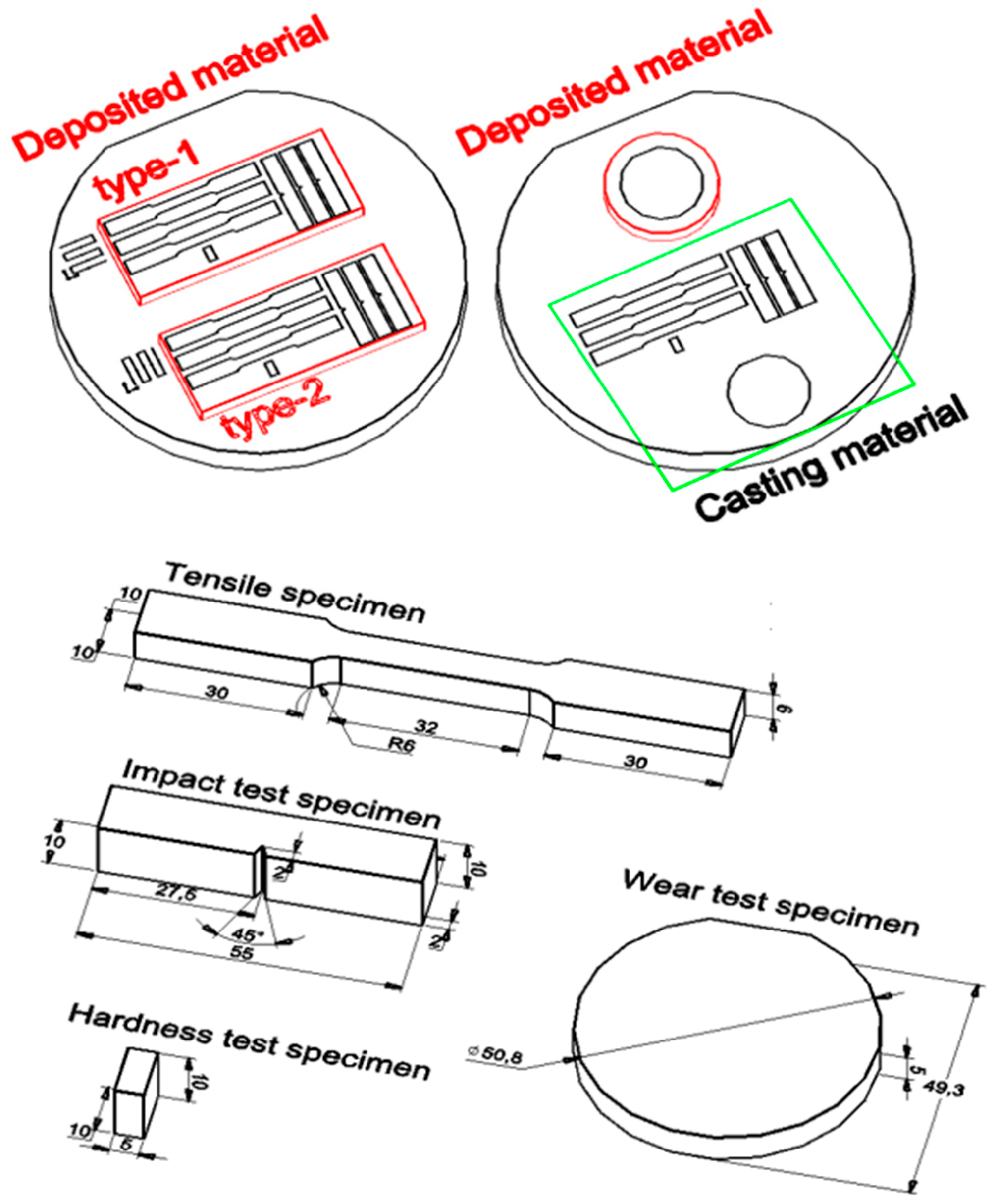
All mechanical properties experiments were performed at room temperature (26 °C), and they were performed to relatively compare the mechanical properties of NAB materials fabricated by cast NAB and WAAM. The specimen coupons for each test were collected from the deposition layer as shown in Figure 2. There are three types of test specimens. These were classified into type 1 and type 2 according to the deposition path, and the substrate was classified as the casting material.
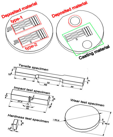
Figure 2.
Definition of measurement points on the bead cross-section (unit: mm).
Wear test specimens were divided into the deposited material and the casting material because they were deposited in a columnar shape, as shown in Table 3.
3. Results and Discussion
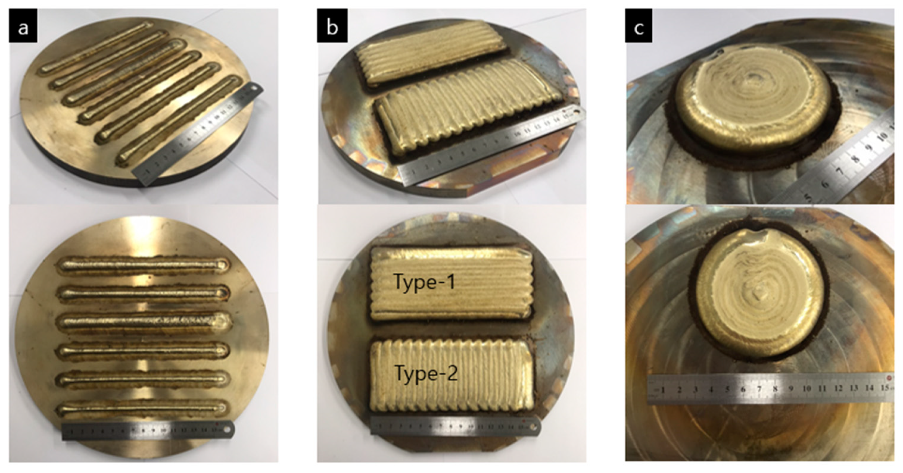
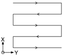
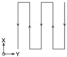
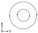
Figure 3 shows the NAB material deposited using WAAM. In all the experiments, the cast NAB was used as a substrate. In Figure 3a, a single bead of about 160 mm was deposited on a round substrate. A total of six conditions were used, and each single bead was tested when the substrate temperature was 26~27 to prevent the base material from preheating. Figure 3b shows a block-type NAB alloy of 150 mm (L) × 60 mm (W) × 25 nm (H) after deposition. The two blocks of the same size have different stacking paths. Welding or deposition by melting a metal causes anisotropy of the metal. When a molten metal is solidified, strong dendrites are formed around a small nucleus, which leads to metal anisotropy [29]. The dendrite direction is determined by the welding direction [30]. Wang modeled the laser heat source and studied the orientation of dendrite around the moving heat source, and Wei [31] reported that in the lamination process using arc welding, the dendrite is determined by the lamination direction. In Figure 3b, type 1 and 2 are deposited in different welding directions; that is, the dendrite direction is different. Figure 3c is a test specimen made by applying a circular deposition path to fabricate a standardized wear test specimen.
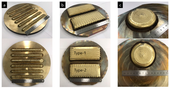
Figure 3.
Three types of test specimens fabricated using WAAM. (a) Bead-on-plate (BOP) test specimens to compare six welding conditions; (b) Two types of test specimen per deposition path; (c) Round test specimen for the wear test.
3.1. Effect of Wire Feed Rate for Single Bead
In the CMT welding process, the wire feed amount is a very critical variable, and its welding conditions are changed according to the wire feed rate. In the CMT welding process, the current and voltage values are determined by wire feed rate through the optimized database. The relationship between the wire feed rate and the current is that a current (A) of 22.50 times that of the wire feed rate (m/min) is supplied. The current amount depends on the welding material type. The average heat input (kJ) per wire feed amount (m/min) is 0.564 kJ·s/cm2, and the standard error is 0.02645 kJ·s/cm2. In addition, a minimum heat input amount of 0.564 kJ·s/cm2 is required to stably melt the wire.
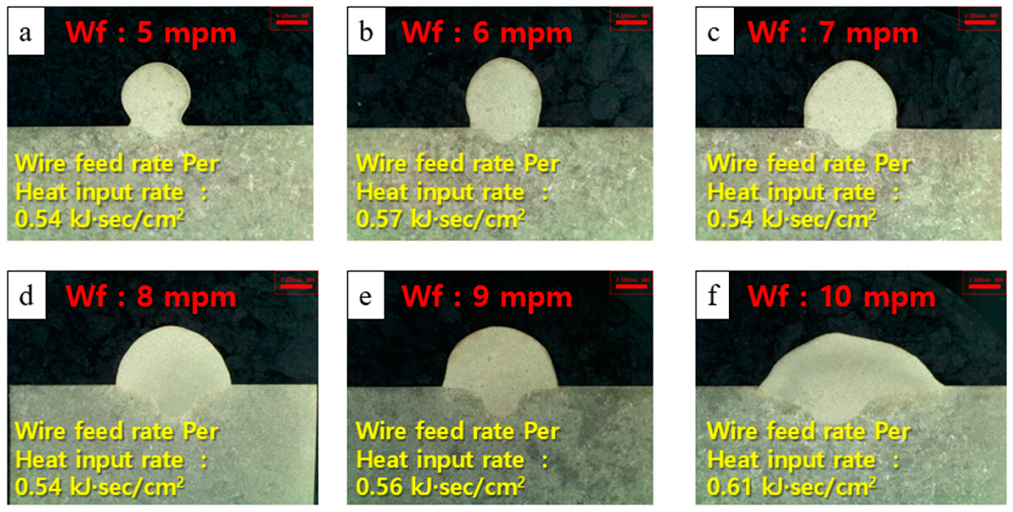
Figure 4 shows the cross-section of a single bead deposited by WAAM for six different wire feed rates. As shown in Figure 4, the bead shape varies depending on wire feeding speed. In Figure 4a,c,d, the wire feed rate per heat input is the same as 0.54 kJ·s/cm2, but the bead shape is different. In Figure 4f, the wire feed rate per heat input rate is larger than the average wire feed rate per heat input rate of 5.6 kJ·s/cm2 by 0.51 kJ·s/cm2. An excessive heat input weakens the surface tension of a bead, and this weakened surface tension causes a non-uniform bead shape.
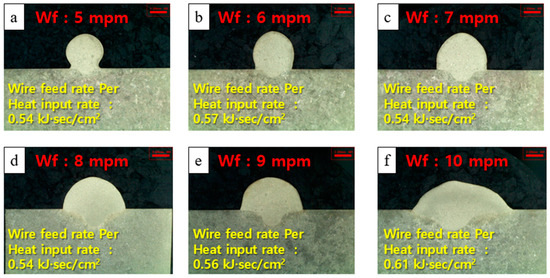
Figure 4.
Macro-section images of single beads according to wire feed rate. (a) Wire feed rate: 5 m/min; (b) Wire feed rate: 6 m/min; (c) Wire feed rate: 7 m/min; (d) Wire feed rate: 8 m/min; (e) Wire feed rate: 9 m/min; (f) Wire feed rate: 10 m/min.
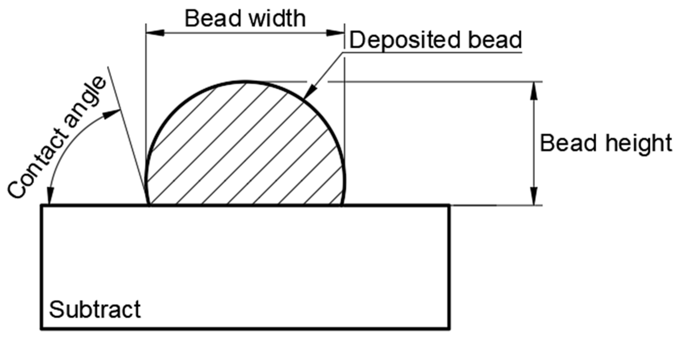
In this study, bead width (mm), bead height (mm), and contact angle (°) were measured as shown in Figure 5 to analyze the effects of welding conditions on the shape of a single bead. The bead width and bead height are very important factors in metal lamination. The width and height of a bead are related to stacking efficiency. Width is a factor that is used to determine the overlap amount of each bead during continuous stacking. Bead height is a factor that determines the number of layers when making a part using WAAM.
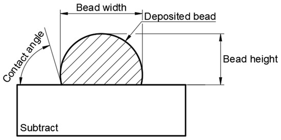
Figure 5.
Measurement points on the bead cross-section.
To analyze the effect of conditions on the shape of a single bead, bead width (mm), bead height (mm), and contact angle (°) were measured, as shown in Figure 5. Bead width and bead height are very critical factors in metal deposition, and are both related to deposition efficiency. The width is a reference factor in determining the overlap amount of each bead during continuous deposition. The bead height is a factor that determines the number of layers when making a part using WAAM.
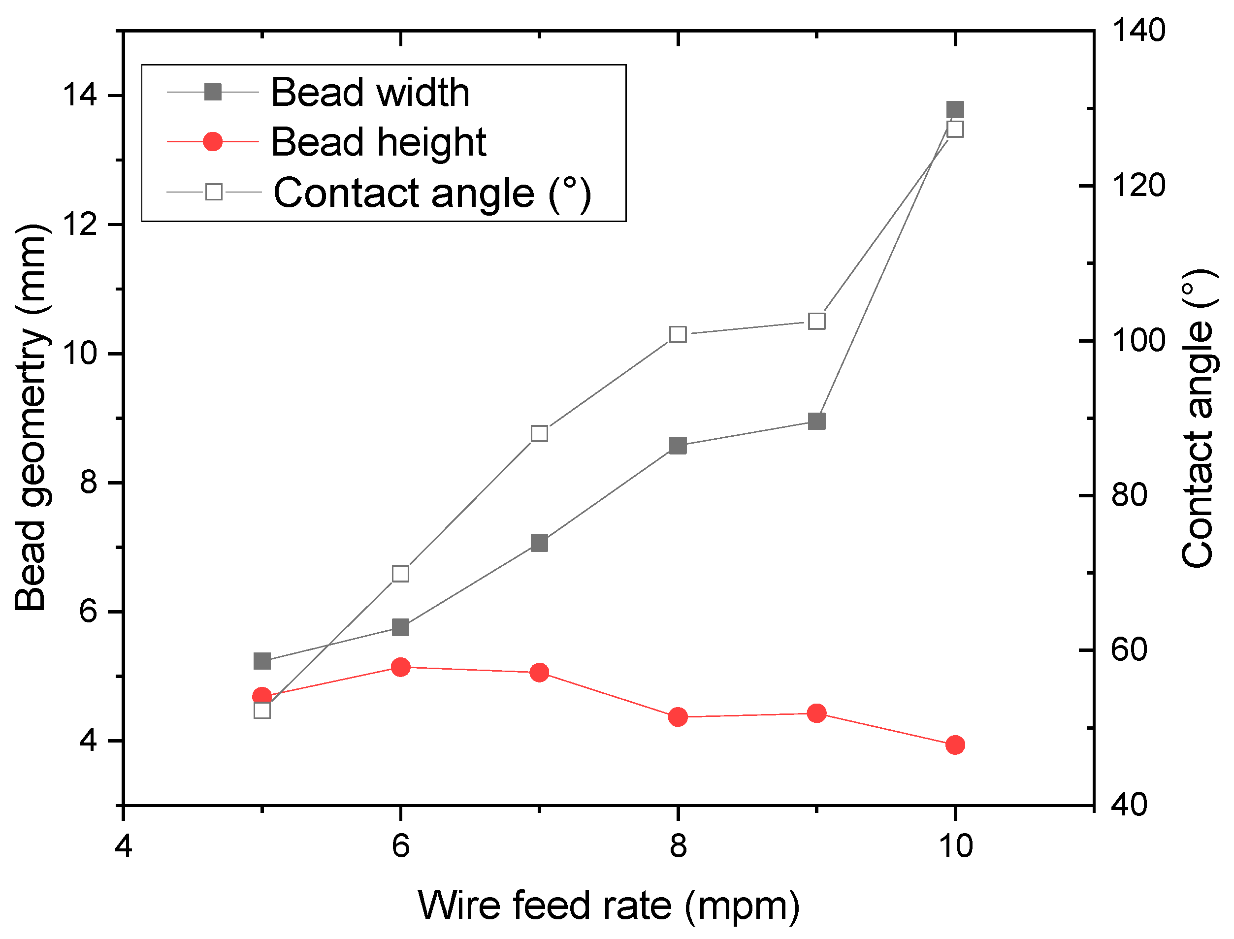
Figure 6 shows the quantitatively measured bead width and contact angle. The bead width increases as the wire feed rate increases; however, the bead height decreases. In addition, as the wire feed rate increases, the contact angle increases. The height and width of a bead are inversely proportional, while the height and contact angle are proportional. The contact angle is an important factor in brazing and cladding [32]. When the contact angle is too large, the individual beads are deposited continuously. As the width of the overlap between the beads increases when the beads are deposited continuously, there is a high possibility that non-uniform beads will be formed [33]. In addition, when the deposition path is bent at 90° or the deposition path is changed, the width of the overlap of beads increases toward the inner diameter direction, which may lead to asymmetry. To minimize the non-uniformity and asymmetry of beads, the contact angle should be close to 90°. Of the six conditions, the contact angle was close to 90° when the wire feed rate is 7 m/min. This study used a wire feed rate of 7 m/min, which supports a contact angle close to 90° for continuous deposition of a single bead.
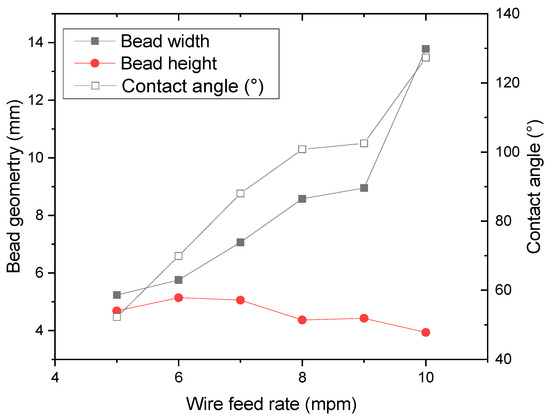
Figure 6.
Geometry fluctuation of beads according to wire feed rate.
3.2. Tensile Strength Results
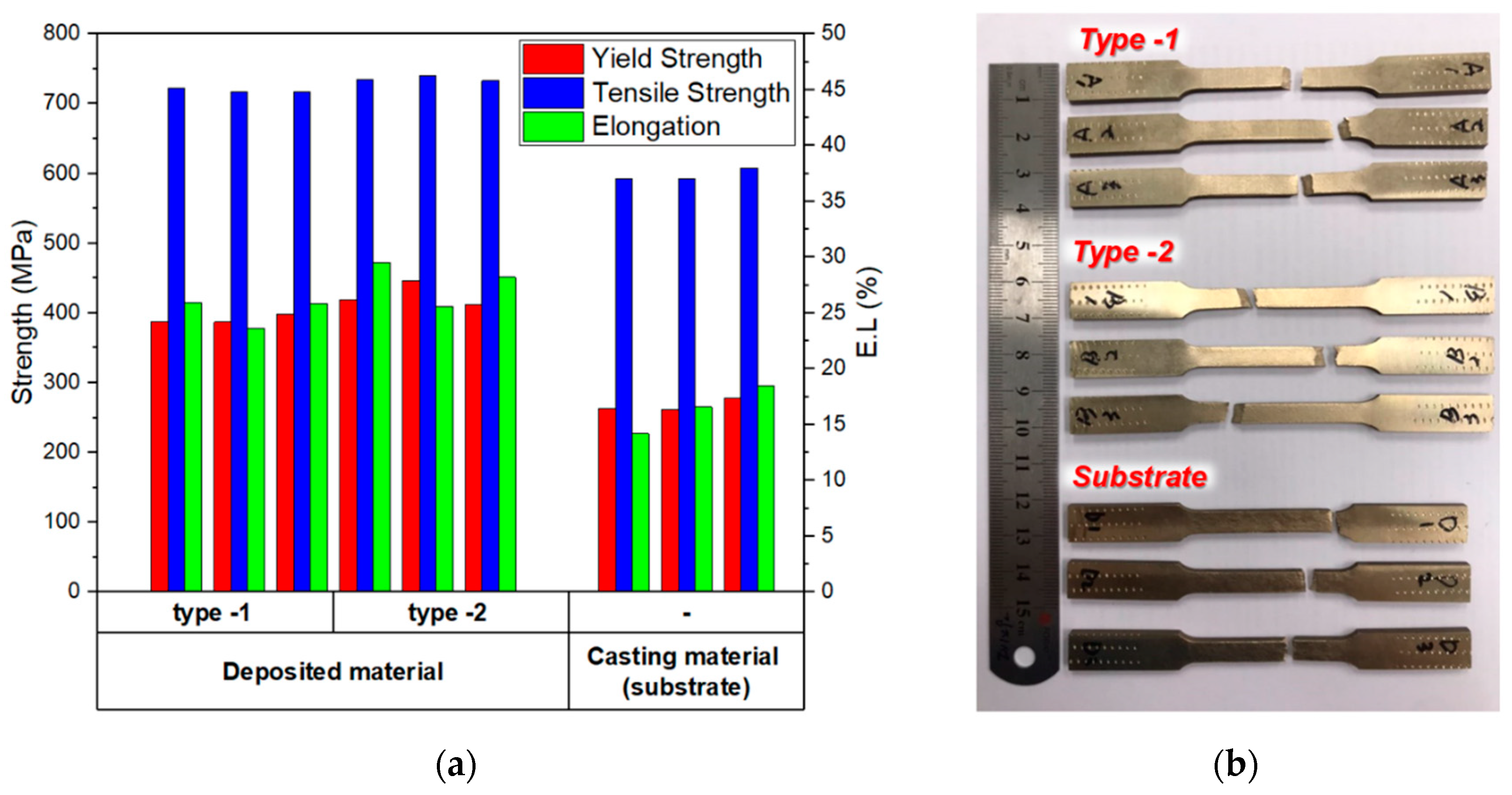
Figure 7 shows the tension testing results. Three specimens were collected from each deposited area as shown in Figure 7b to perform tension testing. In terms of yield strength, tensile strength and elongation, the laminated NAB alloy showed excellent properties. For the cast NAB (substrate), the average tensile strength was 597 MPa, the average yield strength was 267 MPa, and the average elongation was 16.4%. For the deposited NAB, the average tensile strength was 727 MPa, the average yield strength was 408 MPa, and the average elongation was 26.4% regardless of the type. The deposited NAB showed a tensile strength that was increased by 50%, an average yield strength that was increased by 20% and an average elongation that was increased by 60% compared to the cast NAB (substrate) material. In addition, the deposited NAB material is anisotropic. The tensile testing of the deposited NAB materials was performed in two directions. These two directions are divided into type 1 and type 2, where type 1 represents the horizontal direction (transverse) of the welding line and type 2 represents the longitudinal direction of the welding line (longitudinal). The stress differed depending on the tensile direction of the laminated area. Type 1 (transverse direction) showed an average tensile strength of 718 MPa, an average yield strength of 391 MPa and an average elongation of 25.1%. Type 2 (transverse direction) showed an average tensile strength of 735 MPa, an average yield strength of 425 MPa, and an average elongation of 27.7%. The mechanical strength of type 2 showed overall high numbers in the test. The cast alloy has no directionality and has overall uniform strength, ductility and toughness. Stable materials, such as non-directional cast alloys, give us confidence in safety when designing parts. The fact that the deposited NAB material has anisotropy and its mechanical properties differ according to the stacking direction is an important factor to be considered in an actual structural design. It is necessary to design a part by considering material anisotropy after carefully checking the directions of the internal and external forces that the part should withstand.
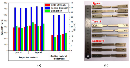
Figure 7.
Comparison of tensile properties in the WAAM-fabricated NAB and the cast NAB (substrate). (a) Results of tensile properties; (b) Specimen after test.
3.3. Hardness
Figure 8 shows four types of specimens for the Vickers hardness test. Figure 8A shows three types of test specimens fabricated to compare the hardness of the deposited NAB material and the cast NAB (substrate) material, while Figure 8B shows a test specimen fabricated to check the hardness distribution of a single bead. The specimens were fabricated through mounting and polishing after sampling.

Figure 8.
Test specimens for hardness measurement. (A) The deposited NAB and the casting material (substrate); (B) Single bead cross-sectional specimen.
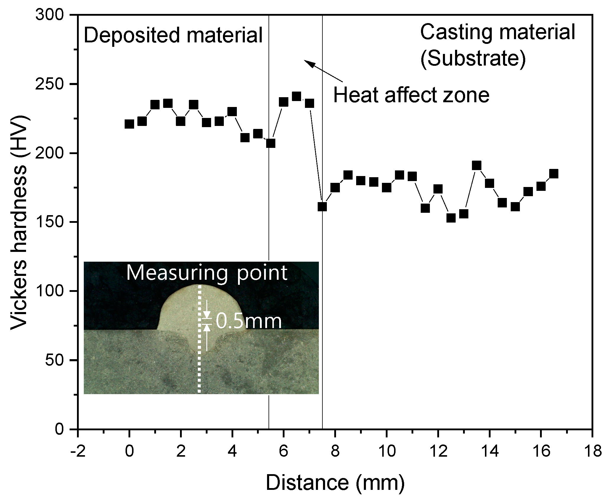
Figure 9 shows the hardness measurement result for a single bead. The hardness was continuously measured from the top of the bead to the bottom of the substrate at 0.5 mm intervals. As shown in Figure 9, the hardness of the deposited material is higher than that of the substrate. The hardness of the HAZ area is similar to or slightly higher than that of the deposited material.

Figure 9.
Hardness of the additively fabricated single bead on the cast NAB alloy.
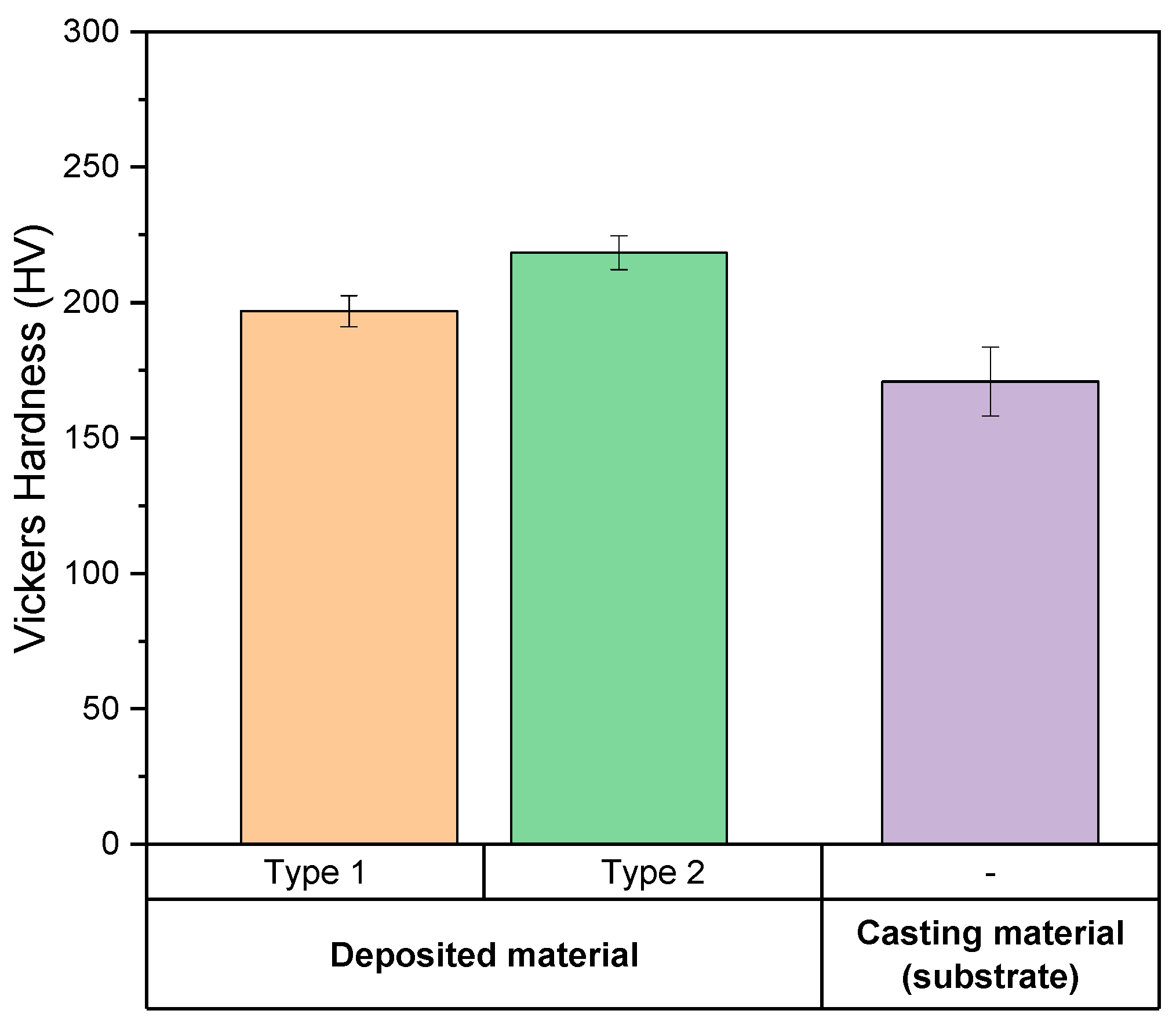
Figure 10 compares the hardness of the deposited NAB material according to stacking direction and the hardness of the casting material. Regarding the hardness test results, type 2 (longitudinal) showed higher numbers, such as the tensile strength test. The average hardness of type 1 (transverse) was 196.8 HV and the average hardness of type 2 (longitudinal) was 218.4 HV. The average hardness of the casting material (substrate) was 170.8 HV. The hardness of type 2 (longitudinal) was improved by 10% compared to type 1 (transverse), and was about 28% improved compared to the casting material (substrate).
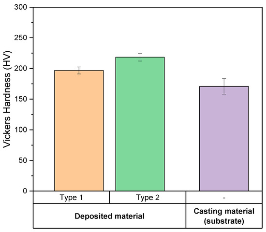
Figure 10.
Comparison of hardness in the WAAM-fabricated NAB (two deposition types) and the cast NAB.
3.4. Impact Test Results
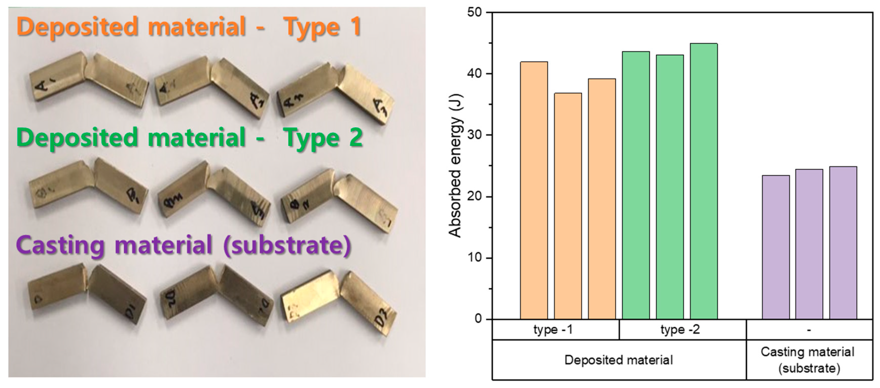
Figure 11 shows the impact test to evaluate the impact strength of the deposited material. The average absorbed energy (J) of the deposited material is about 41.61 J. The average absorbed energy (J) of the deposited material is significantly higher than that (24.3 J) of the casting material. In addition, the impact strength of the deposited NAB material showed differences depending on the impact direction (stacking direction). The average absorbed energy (J) of type 1 (transverse) is 39.32 J, and the average hardness of type 2 (longitudinal) is 43.86 J, which is about an 11.6% improvement.
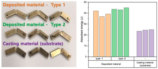
Figure 11.
Comparison of absorbed energy in the WAAM-fabricated NAB (two deposition type) and the cast NAB.
3.5. Wear Test Results
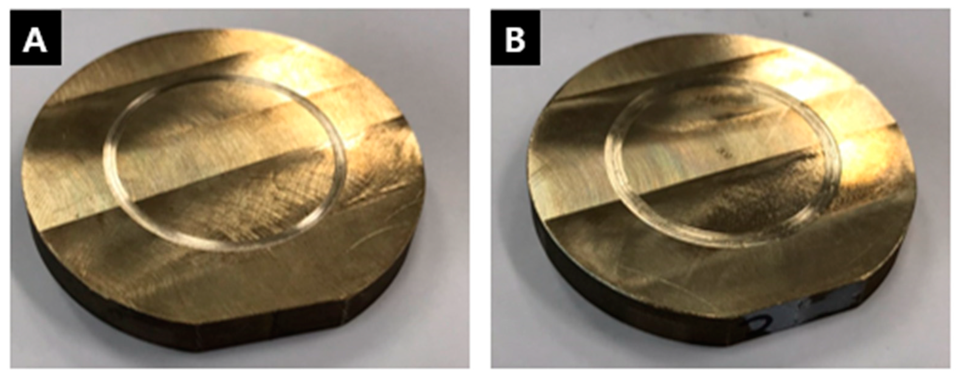
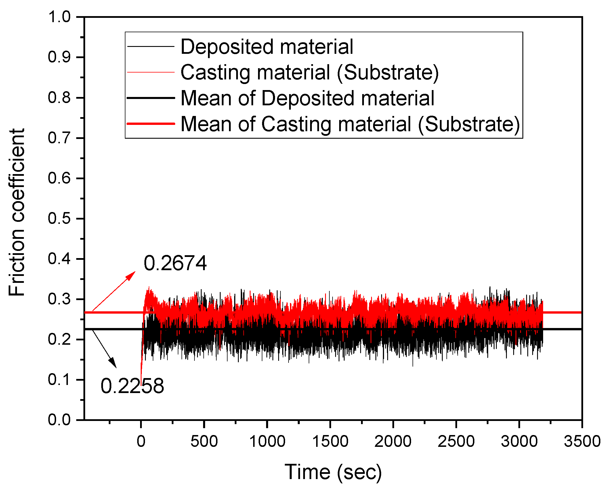
The NAB alloy is commonly used in abrasion environments, such as impellers for seawater pumps, propellers for ships, oil chambers, and landing gear and wing flap bearings of aircraft. This study compared the abrasion performance of the deposited NAB material and the casting material. Figure 12 shows a test specimen that has gone through a ball-on-disk wear test. Figure 12A displays the NAB material fabricated by casting, and Figure 12B displays the deposited NAB material fabricated by WAAM. Both specimens were tested in the same environment to evaluate friction coefficient, wear depth, and weight loss. Figure 13 shows the friction coefficient of the two materials. The friction coefficient was measured as 0.2258 for the deposited material and 0.2674 for the cast NAB. The friction coefficient is a coefficient of physical friction between the alumina oxide ball and the NAB material. The deposited material showed better performance that the cast NAB material in terms of the wear loss and frictional heat resistance that can occur due to friction.
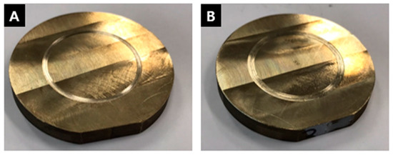
Figure 12.
Wear tested specimens: (A) Casting material (substrate); (B) Deposited material.
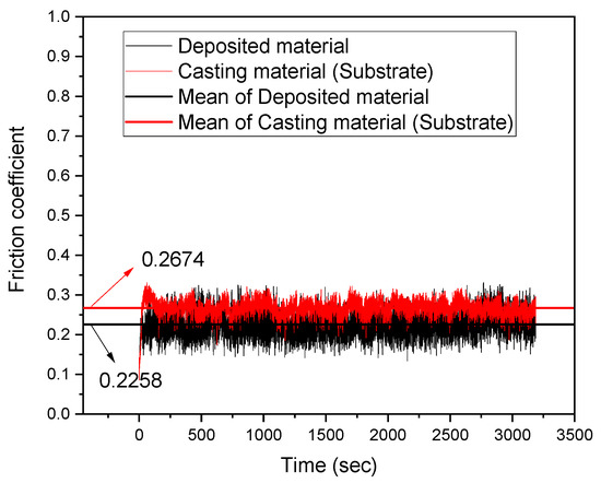
Figure 13.
Comparison of the friction coefficient in the WAAM-fabricated NAB and the cast NAB (substrate).
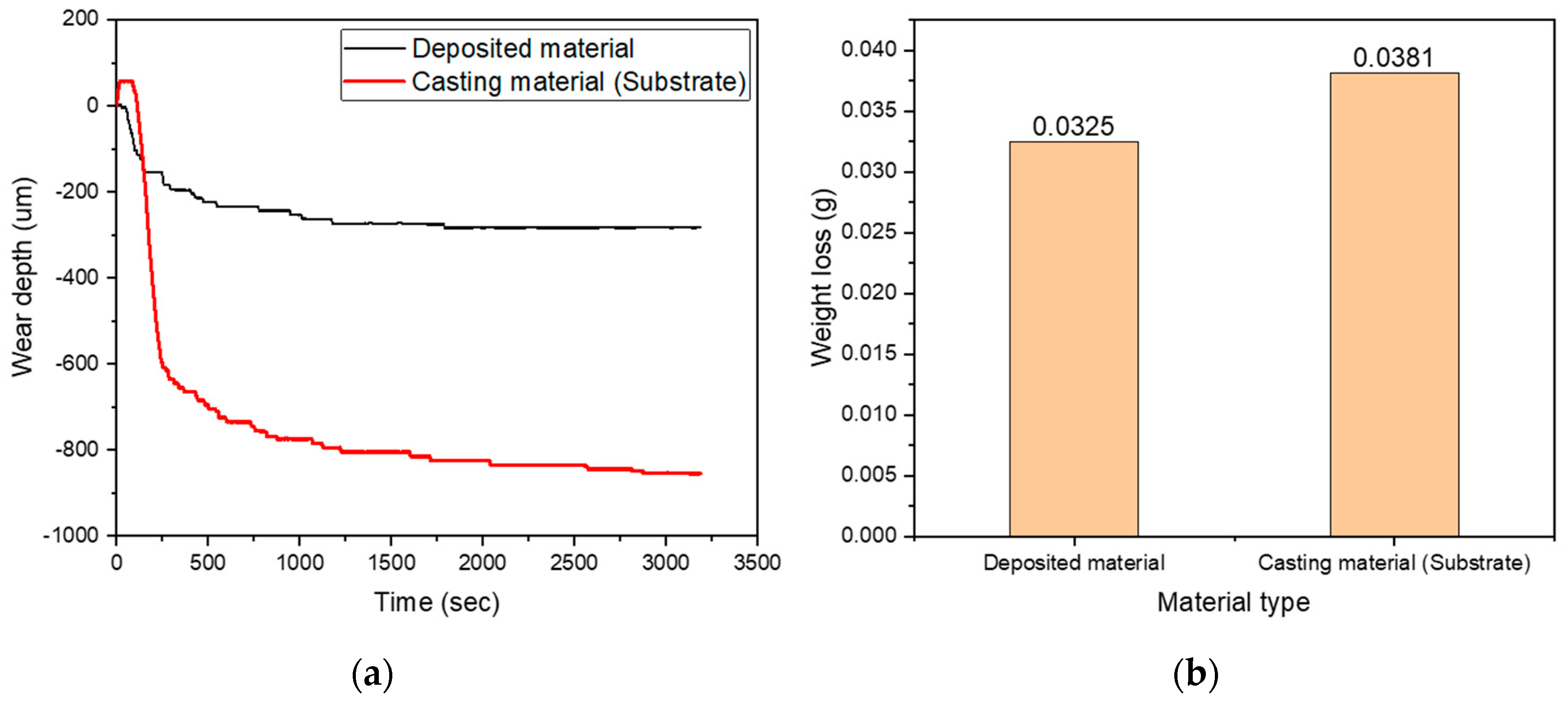
Figure 14a shows the measured wear depth of the deposited NAB and the cast NAB. When friction occurs for 500 m under the pressure of final 100 N force, the deposited NAB material showed an indentation mark of 200 μm. However, the cast NAB showed an indentation of 800 μm. In addition, although the indentation depth continuously increased as time passed for the cast NAB material, the indentation depth of the deposited NAB material was stable after 2000 s. As shown in Figure 14b, the difference in weight loss occurred as much as the difference in the indentation amount, and the deposited NAB material showed a weight loss of 0.0325 g. The weight loss of the cast NAB was 0.0381 g, which is a relatively large amount compared to the deposited NAB material.

Figure 14.
Comparison of wear properties in the WAAM-fabricated NAB and the cast NAB (substrate): (a) Wear depth; (b) Weight loss.
4. Conclusions
This study fabricated a block bulk material to evaluate the shape of a single bead and mechanical properties by depositing the Ni-Al-bronze alloy using WAAM (wire arc additive manufacturing) technology, analyzed the cross-section of a single bead, and performed mechanical and physical properties tests. The study obtained the following conclusions:
- The study analyzed the shape of an NAB single bead using the CMT process and found that the wire feed rate per heat input needs a minimum heat input of 0.54 kJ·s/cm2, and that the contact angle becomes closer to 90° when the wire feed rate is about 7 m/min. A contact angle close to 90° is required to make a single bead shape suitable for the deposition process.
- Regarding the tensile strength results, the deposited NAB showed 50% higher tensile strength, 20% higher average yield strength, and 60% higher average elongation compared to the cast NAB (substrate). The NAB material fabricated by WAAM has anisotropy, and the stress results differed depending on the tensile direction of laminated part. The average tensile strength was 718 MPa, the average yield strength was 391 MPa, and the average elongation was 25.1% for type 1 (transverse direction). For type 2 (transverse direction), the average tensile strength was 735 MPa, the average yield strength was 425 MPa, and the average elongation was 27.7%.
- Regarding the Vickers hardness measurement results, type 2 (longitudinal) showed higher hardness, which is similar to the tensile strength test results. The average hardness of type 1 (transverse) was 196.8 HV, and the average hardness of type 2 (longitudinal) was 218.4 HV. The average hardness of the casting material (substrate) was 170.8 HV. The hardness of type 2 (longitudinal) was improved by 10% compared to type 1 (transverse), and by about 28% compared to the casting material (substrate).
- Regarding the wear test results, the abrasion resistance of the deposited NAB material showed better performance than that of the casting material (substrate) in terms of indentation depth and weight loss. In addition, the friction coefficient of the deposited NAB was smaller than that of the casting material (substrate), so there is less part damage caused by friction.
In a general welding process, the deposited NAB’s mechanical properties were better than those of the casting material (substrate), and the deposited NAB showed anisotropy. Although the mechanical properties are excellent, it is necessary to consider anisotropy when designing a part.
Author Contributions
Conceptualization, J.K. (Jisun Kim), J.K. (Jaewoong Kim) and C.P.; experiment, J.K. (Jisun Kim); software, C.P.; validation, C.P., J.K. (Jaewoong Kim) and J.K. (Jisun Kim); paper research, C.P., J.K. (Jaewoong Kim) and J.K. (Jisun Kim); data analysis, J.K. (Jisun Kim) and J.K. (Jaewoong Kim); writing—original draft preparation, J.K. (Jisun Kim); writing—review and editing, J.K. (Jisun Kim) and C.P.; supervision, J.K. (Jaewoong Kim); project administration, J.K. (Jaewoong Kim). All authors have read and agreed to the published version of the manuscript.
Funding
This study has been conducted with the support of the Korea Institute of Industrial Technology as “Development of Core Technologies for a Smart Mobility (PJA20073)”.
Conflicts of Interest
The authors declare no conflict of interest.
References
- Shahrubudin, N.; Lee, T.; Ramlan, R. An Overview on 3D Printing Technology: Technological, Materials, and Applications. Procedia Manuf. 2019, 35, 1286–1296. [Google Scholar] [CrossRef]
- Nichols, M.R. How does the automotive industry benefit from 3D metal printing? Met. Powder Rep. 2019, 74, 257–258. [Google Scholar] [CrossRef]
- Kim, S.; Lim, S.; Chun, C.-K. Repair Properties of Desulfurization Pump Part Layers by Direct Energy Deposited Additive Manufacturing Process. J. Weld. Join. Soc. 2020, 38, 92–97. [Google Scholar] [CrossRef]
- Byun, J.-G.; Cho, S.M. Trend of Metal 3D Printing by Welding. J. Weld. Join. Soc. 2016, 34, 1–8. [Google Scholar] [CrossRef][Green Version]
- Hwa, L.C.; Rajoo, S.; Noor, A.M.; Ahmad, N.; Uday, M. Recent advances in 3D printing of porous ceramics: A review. Curr. Opin. Solid State Mater. Sci. 2017, 21, 323–347. [Google Scholar] [CrossRef]
- Kam, D.-H.; Kim, Y.-M.; Kim, C. Recent Studies of Laser Metal 3D Deposition with Wire Feeding. J. Weld. Join. Soc. 2016, 34, 35–40. [Google Scholar] [CrossRef]
- Karakurt, I.; Lin, L. 3D printing technologies: Techniques, materials, and post-processing. Curr. Opin. Chem. Eng. 2020, 28, 134–143. [Google Scholar] [CrossRef]
- Cunningham, C.; Flynn, J.; Shokrani, A.; Dhokia, V.; Newman, S. Invited review article: Strategies and processes for high quality wire arc additive manufacturing. Addit. Manuf. 2018, 22, 672–686. [Google Scholar] [CrossRef]
- Wu, B.; Pan, Z.; Ding, D.; Cuiuri, D.; Li, H.; Xu, J.; Norrish, J. A review of the wire arc additive manufacturing of metals: Properties, defects and quality improvement. J. Manuf. Process. 2018, 35, 127–139. [Google Scholar] [CrossRef]
- Lin, J.; Lv, Y.; Liu, Y.; Xu, B.; Sun, Z.; Li, Z.; Wu, Y. Microstructural evolution and mechanical properties of Ti-6Al-4V wall deposited by pulsed plasma arc additive manufacturing. Mater. Des. 2016, 102, 30–40. [Google Scholar] [CrossRef]
- Wu, B.; Pan, Z.; Ding, D.; Cuiuri, D.; Li, H. Effects of heat accumulation on microstructure and mechanical properties of Ti6Al4V alloy deposited by wire arc additive manufacturing. Addit. Manuf. 2018, 23, 151–160. [Google Scholar] [CrossRef]
- Bermingham, M.; Nicastro, L.; Kent, D.; Chen, Y.; Dargusch, M. Optimising the mechanical properties of Ti-6Al-4V components produced by wire + arc additive manufacturing with post-process heat treatments. J. Alloys Compd. 2018, 753, 247–255. [Google Scholar] [CrossRef]
- Wu, B.; Pan, Z.; Ding, D.; Cuiuri, D.; Li, H.; Fei, Z. The effects of forced interpass cooling on the material properties of wire arc additively manufactured Ti6Al4V alloy. J. Mater. Process. Technol. 2018, 258, 97–105. [Google Scholar] [CrossRef]
- Wang, J.; Sun, Q.; Wang, H.; Liu, J.; Feng, J. Effect of location on microstructure and mechanical properties of additive layer manufactured Inconel 625 using gas tungsten arc welding. Mater. Sci. Eng. A 2016, 676, 395–405. [Google Scholar] [CrossRef]
- Rojas, J.M.; Wolfe, T.; Fleck, B.; Qureshi, A.J. Plasma transferred arc additive manufacturing of Nickel metal matrix composites. Manuf. Lett. 2018, 18, 31–34. [Google Scholar] [CrossRef]
- Yang, X.; Liu, J.; Wang, Z.; Lin, X.; Liu, F.; Huang, W.; Liang, E. Microstructure and mechanical properties of wire and arc additive manufactured AZ31 magnesium alloy using cold metal transfer process. Mater. Sci. Eng. A 2020, 774, 138942. [Google Scholar] [CrossRef]
- Takagi, H.; Sasahara, H.; Abe, T.; Sannomiya, H.; Nishiyama, S.; Ohta, S.; Nakamura, K. Material-property evaluation of magnesium alloys fabricated using wire-and-arc-based additive manufacturing. Addit. Manuf. 2018, 24, 498–507. [Google Scholar] [CrossRef]
- Xu, X.; Ganguly, S.; Ding, J.; Guo, S.; Williams, S.; Martina, F. Microstructural evolution and mechanical properties of maraging steel produced by wire + arc additive manufacture process. Mater. Charact. 2018, 143, 152–162. [Google Scholar] [CrossRef]
- Yang, F.; Kang, H.; Chen, Z.; Guo, E.; Zeng, Y.; Wang, W.; Wang, T. Electrochemical corrosion mechanisms of nickel-aluminium bronze with different nickel contents using the rotating disc electrode. Corros. Sci. 2019, 157, 438–449. [Google Scholar] [CrossRef]
- Wharton, J.A.; Barik, R.; Kear, G.; Wood, R.J.K.; Stokes, K.; Walsh, F. The corrosion of nickel–aluminium bronze in seawater. Corros. Sci. 2005, 47, 3336–3367. [Google Scholar] [CrossRef]
- Lv, Y.; Ding, Y.; Cui, H.; Liu, G.; Wang, B.; Cao, L.; Li, L.; Qin, Z.; Lu, W. Investigation of microscopic residual stress and its effects on stress corrosion behavior of NiAl bronze alloy using in situ neutron diffraction/EBSD/tensile corrosion experiment. Mater. Charact. 2020, 164, 110351. [Google Scholar] [CrossRef]
- Cunningham, C.; Wikshåland, S.; Xu, F.; Kemakolam, N.; Shokrani, A.; Dhokia, V.; Newman, S. Cost Modelling and Sensitivity Analysis of Wire and Arc Additive Manufacturing. Procedia Manuf. 2017, 11, 650–657. [Google Scholar] [CrossRef]
- Hazra, M.; Balan, K. Failure of a nickel aluminium bronze (NAB) canned motor pump impeller working under polluted sea water–Influence of material selection, section thickness dependent microstructure and temper annealing heat treatment. Eng. Fail. Anal. 2016, 70, 141–156. [Google Scholar] [CrossRef]
- Zhao, B.; Lv, Y.; Ding, Y.; Wang, L.; Lu, W. The grain refinement mechanisms of various phases in shot-peened Nickel-Aluminum bronze (NAB) alloy. Mater. Charact. 2018, 144, 77–85. [Google Scholar] [CrossRef]
- Li, Y.; Lian, Y.; Sun, Y. Cavitation erosion behavior of friction stir processed nickel aluminum bronze. J. Alloys Compd. 2019, 795, 233–240. [Google Scholar] [CrossRef]
- Dharmendra, C.; Shakerin, S.; Ram, G.J.; Mohammadi, M. Wire-arc additive manufacturing of nickel aluminum bronze/stainless steel hybrid parts–Interfacial characterization, prospects, and problems. J. Mater. 2020, 13, 100834. [Google Scholar] [CrossRef]
- Dharmendra, C.; Hadadzadeh, A.; Amirkhiz, B.; Ram, G.J.; Mohammadi, M. Microstructural evolution and mechanical behavior of nickel aluminum bronze Cu-9Al-4Fe-4Ni-1Mn fabricated through wire-arc additive manufacturing. Addit. Manuf. 2019, 30, 100872. [Google Scholar] [CrossRef]
- Shen, C.; Pan, Z.; Ding, D.; Yuan, L.; Nie, N.; Wang, Y.; Luo, D.; Cuiuri, D.; Van Duin, S.; Li, H. The influence of post-production heat treatment on the multi-directional properties of nickel-aluminum bronze alloy fabricated using wire-arc additive manufacturing process. Addit. Manuf. 2018, 23, 411–421. [Google Scholar] [CrossRef]
- Li, Y.; Li, S.; Yang, L.; Zhong, H. Microstructure and properties of twinned dendrites in directionally solidified A356 alloy. Mater. Sci. Eng. A 2018, 734, 7–19. [Google Scholar] [CrossRef]
- Wang, L.; Wei, Y.; Zhan, X.; Yu, F.; Cao, X.; Gu, C.; Ou, W. Simulation of dendrite growth in the laser welding pool of aluminum alloy 2024 under transient conditions. J. Mater. Process. Technol. 2017, 246, 22–29. [Google Scholar] [CrossRef]
- Wei, H.L.; Mazumder, J.; Debroy, T. Evolution of solidification texture during additive manufacturing. Sci. Rep. 2015, 5, 16446. [Google Scholar] [CrossRef] [PubMed]
- Dinovitzer, M.; Chen, X.; Laliberte, J.; Huang, X.; Frei, H. Effect of wire and arc additive manufacturing (WAAM) process parameters on bead geometry and microstructure. Addit. Manuf. 2019, 26, 138–146. [Google Scholar] [CrossRef]
- Spaniol, E.; Ungethüm, T.; Trautmann, M.; Andrusch, K.; Hertel, M.; Füssel, U. Development of a novel TIG hot-wire process for wire and arc additive manufacturing. Weld. World 2020, 64, 1329–1340. [Google Scholar] [CrossRef]
© 2020 by the authors. Licensee MDPI, Basel, Switzerland. This article is an open access article distributed under the terms and conditions of the Creative Commons Attribution (CC BY) license (http://creativecommons.org/licenses/by/4.0/).

