Article

On the Effect of Electron Beam Melted Ti6Al4V Part Orientations during Milling

Industrial Engineering Department, College of Engineering, King Saud University, PO Box 800, Riyadh 11421, Saudi Arabia
*
Author to whom correspondence should be addressed.
Metals 2020, 10(9), 1172; https://doi.org/10.3390/met10091172
Submission received: 27 July 2020 / Revised: 25 August 2020 / Accepted: 26 August 2020 / Published: 1 September 2020
(This article belongs to the Special Issue Electron Beam Treatment Technology in Metals)

Abstract

:
The machining of the electron beam melting (EBM) produced parts is a challenging task because, upon machining, different part orientations (EBM layers’ orientations) produce different surface quality even when the same machining parameters are employed. In this paper, the EBM fabricated parts are machined in three possible orientations with regard to the tool feed direction, where the three orientations are “tool movement in a layer plane” (TILP), “tool movement perpendicular to layer planes” (TLP), and “tool movement parallel to layers planes” (TPLP). The influence of the feed rate, radial depth of cut, and cutting speed is studied on surface roughness, cutting force, micro-hardness, microstructure, chip morphology, and surface morphology of Ti6Al4V, while considering the EBM part orientations. It was found that different orientations have different effects on the machined surface during milling. The results show that the EBM parts can achieve good surface quality and surface integrity when milled along the TLP orientation. For instance, surface roughness (Sa) can be improved up to 29% when the milling tool is fed along the TLP orientation compared to the other orientations (TILP and TPLP). Furthermore, surface morphology significantly improves with lower micro-pits, redeposited chips, and feed marks in case of the TLP orientation.

1. Introduction

Titanium alloys have gained significant interest in recent years with the advent of additive manufacturing (AM) techniques. Ti6Al4V titanium alloy is extensively used in biomedical implants [1], marine applications [2], and the aerospace industry [3]. This is due to its favorable properties, such as good biocompatibility, corrosion resistance, and high performance at elevated temperatures [4]. However, Ti6Al4V is considered a difficult-to-machine material. This is because of its low thermal conductivity and high affinity with tool materials and its tendency to cold weld on the tool edges during machining processes, which causes chipping and premature tool failure as explained by Sharif and EA Rahim [5]. The high strain hardening deteriorates its machinability even further. To increase machining output, high-speed machining of different materials has been proposed and applied, but the use of high-speed machining for titanium alloys is not preferred because of the high thermal load produced in the cutting material [6]. Therefore, extensive work on the machinability of Ti6Al4V is required to achieve the desired surface integrity.
Several applications of additive manufacturing (AM) have been demonstrated in the medical and aerospace industries [7]. For example, Hassanin et al. [8] developed drug-delivering implant devices with titanium alloy the via selective laser melting (SLM) process for potential orthopedic or dental applications. They fabricated the internal reservoirs and releasing micro-channels within these devices. GE Aviation has demonstrated the use of AM for producing complex-shaped fan blades with optimized heat dissipation and airflow [9]. Furthermore, GE Aviation has also used the AM technologies to simplify parts design by combining multiple components, such as GE fuel nozzles [10]. AM has the potential to produce lighter and high strength parts compared to the conventional manufacturing methods. For instance, Airbus developed 30% lighter brackets for the A350 XWB and reduced the manufacturing time by about 75% [11]. AM also has the potential to create shapes that are optimized for multiple functions simultaneously. For example, Maloney et al. [12] developed multi-functional heat exchangers by employing 3D micro-lattice structures. In acoustic applications, such as sound insulation or sound cloaking, this can also be optimized with the help of AM [13]. Heinl et al. [14] used electron beam melting (EBM) to produce lattice structured porous implants with low stiffness and high strength to reduce the stiffness difference between the implant and the bone.
EBM is a direct metal layer by layer manufacturing method used to manufacture complicated 3D components such as surgical implants and conformal cooling channel tools [15]. The EBM technology selectively fuses the metal powder in layers between 0.07 and 0.25 mm in thickness. First, each layer is preheated by exposing the powder to a high-velocity and low-power beam to gently sinter the powder particles. EBM has a higher energy density compared to lasers, which results in lower costs and times, as mentioned by Parthasarathy et al. [16]. EBM distinguishes itself from other additive manufacturing processes by producing parts with low residual stresses and good dimensional accuracy. However, some defects remain, such as the high surface roughness [17], and the need for support structures [18]. In the following, some studies that have focused on improving the roughness of Ti6Al4V parts by tuning the process parameters of EBM are reviewed. Safdar et al. [19] studied the effect of EBM process parameters on roughness/topography of the Ti6Al4V parts. The surface roughness Ra ranged from 1 to 20 μm depending on the thickness and process parameter settings. It should be noted that for thicker parts, with thicknesses of 5.42 and 1.59 mm, the roughness was in the range of 4.29 and 17.25 µm, respectively. Their results show that increasing the scanning speed and offset concentration reduced the Ra value. The Ra value increased with the beam current and sample thickness. Wang et al. [20] focused on the difference between non-multi-spot and multi-spot EBM processing parameters for Ti6Al4V. They obtained improved surface roughness in both types of processing systems using the non-multi-spot contouring scanning technique. In optimized conditions, the horizontal and vertical surface roughness values were 20 and 24 μm, respectively. In comparison, the multi-spot processed counterparts had roughness values of approximately 27 μm for both the horizontal and vertical roughness under optimized conditions.
Greitemeier et al. [21] investigated the effects of inherent roughness on the fatigue performance of Ti6Al4V parts for both EBM and direct metal laser sintering (DMLS) with varying process machine type, power, scan speed, and layer thickness. The roughness of EBM parts was higher (Ra ≈ 27 µm) relative to the DMLS parts (Ra ≈ 13 µm). However, these surface roughness values are still high to be applied in several applications, e.g., implants [22] and aerospace parts [23]. Masuo et al. [24] investigated the influence of process defects, hot isostatic pressing (HIP), and surface roughness on the fatigue strength of Ti6Al4V fabricated by DMLS and EBM. The defects comprised gas pores resulting from a lack of fusion. They concluded that many pores formed near the surfaces were eliminated by HIP and that the roughness of the surface had a more damaging effect on the fatigue strength than other defects commonly found in additively manufactured materials. Ameen [17] investigated the impact of support structure design on roughness (Ra) and support removability in EBM of Ti6Al4V overhanging components. They found for the parts with the lowest support removal time had an Ra of 21.9 μm, while the parts with the highest support removal time had an Ra of 20.68 μm. In both cases, very high roughness was observed. Although some studies have been performed regarding minimizing the roughness of Ti6Al4V components produced by the process of EBM, there is still a need for secondary processing to decrease the high surface roughness (Ra ≈ 20 µm) of the EBM parts [25]. Biffi et al. [26] studied the effects of different EBM scanning strategies (factory parameters, full-hatch, full contour in-out, and out-in strategy) on the microstructure, surface morphology, relative density, and mechanical properties of theTi6Al4V EBM parts along the two principal orientations (XZ and XY planes). Their results showed that a minimum surface roughness of Sa = 7.5 µm and Sa = 21 µm was achieved on the top (XY plane) and side surfaces (XZ plane), respectively. However, their work was limited to study the effect of the scan strategies, and unlike in the current study, no machining trials were performed to improve the surface finish of the EBM parts. Gupta et al. [27] studied the impact of layer rotation on the microstructure, grain size, surface topography, residual stresses, and mechanical behavior of selective laser melted (SLM) Al-Si-10Mg alloy. They examined the process performance by varying the layer rotation values at three different angles i.e., 0°, 45°, and 90°. The result of the microstructural analysis revealed that the SLM Al-Si-10Mg having fewer pores and defects at the 90° layer rotation angle. Furthermore, the micro-hardness, tensile strength, percentage elongation, and relative density values were significantly enhanced at a higher angle of layer rotations. This is mainly due to the reduction in porosity and better interlayer metallurgical bonding.
Hassanin et al. [28] developed a hybrid approach to improve SLM productivity for shell-shaped parts by combining it with hot isostatic pressing (HIP). They performed the finite element (FE) analysis of the HIP process of shell parts encapsulating the Ti6Al4V powder and validated the simulations results with the experimental ones. Similar work was also reported by Qiu et al. [29] to produce in-situ powder-filled shells, which were later consolidated by the HIP process. They reported that the adopted route enhances productivity. They also conducted an FE analysis to choose the correct shell design. However, in both the previous works [28,29], the surface quality of the produced parts was not discussed.
Several studies on traditional titanium alloys have been carried out [30] to understand the machining integrity of induced surfaces, but very little knowledge is available for machining parts developed using additive manufacturing techniques [31]. Some milling studies on wrought Ti6Al4V have been performed; however, there is a difference between the machinability of EBM and wrought Ti6Al4V, as reported by Bordin et al. [32]. Compared to the conventional Ti6Al4V alloy, the EBM-fabricated materials show a unique microstructure and properties [33]. The EBM Ti6Al4V alloy showed better wear resistance than the conventional Ti6Al4V alloy, which correlates to their higher hardness and weaker delamination [34]. In addition, the microstructural features of EBM Ti6Al4V indicate lower machinability in comparison with conventional Ti6Al4V [32]. Ginta et al. [35] predicted the minimum surface roughness (0.17 μm) produced in end milling of titanium alloy Ti6Al4V using uncoated inserts under dry conditions. They employed a central composite design of response surface methodology to create an efficient analytical model for surface roughness in terms of cutting parameters: cutting speed, axial depth of cut, and feed per tooth. The results show that feed was the most dominant cutting condition on surface roughness. Furthermore, Zhang and Li [36] investigated the surface roughness, surface topography and tool wear during high-speed end milling of the Ti6Al4V alloy with uncoated carbide inserts. They achieved the minimum surface roughness (Ra) of 0.20 μm during the milling process.
Al-Rubaie et al. [37] evaluated the machinability of as-fabricated SLM Ti6Al4V parts (SLM-AB), stress-relief SLM parts (SLM-SR) and conventional Ti6Al4V parts on surface roughness, cutting force, tool wear, and chip morphology via milling. They concluded that the cutting parameters used to machine the conventionally Ti6Al4V alloy are also valid for machining the SLM Ti6Al4V alloy. However, this study did not consider the effect of the SLM part orientations during milling. Hassanin et al. [37] introduced a hybrid microfabrication technology that combines both the freedom design of SLM and the high surface quality of microwire electrical discharge machining (μ-WEDM). Their aim was to manufacture high-quality micro implantable components with the highest density and the best surface quality. They improved the surface quality and flatness of the SLM parts via μ-WEDM. They reported a high surface roughness of around 14.6 μm for the as-fabricated SLM part, while the roughness reduced between 0.6 and 0.8 μm after μ-WEDM. It should be noted that the EDM process removes materials by a thermal/melting phenomenon and a heat-affected zone (HAZ) is commonly reported by the EDM processes [38]. However, no results were presented in their work regarding the HAZ. Furthermore, this study did not take into account the effect of the EBM part orientations.
In addition, the EBM layers also have a significant effect on machinability. Only a few studies focusing on improving the surface quality of EBM-produced Ti6Al4V exist in the literature. In the following, studies reporting on the machining of EBM-produced Ti6Al4V are discussed. Bruschi et al. [39] studied the effects of cooling approaches and turning parameters on the wear behavior of EBM and wrought Ti6Al4V cylinders under conditions of cryogenic cooling and dry cutting. The study found that the wear behavior of the Ti6Al4V greatly improved with the implementation of cryogenic cooling during machining because of the reduced release of metal debris compared with dry cutting conditions. However, they did not consider improving the surface finish of EBM-produced Ti6Al4V or the effects of the EBM Ti6Al4V part orientation. Bordin et al. [32] compared the machinability of the wrought and EBM-produced Ti6Al4V in the external finish turning through evaluating the influence of the feed rate and cutting speed on surface integrity, microstructure, chip morphology, and tool wear. Their findings showed that the EBM alloy was higher in surface roughness. For both alloys, the surface quality was affected by the feed rate. The chips were segmented, and 20-μm-thick deformed microstructures were observed. In the wrought alloy, the periodicity of the chip profiles increased with feed rate and cutting speed, while in the EBM alloy, a transitional chip was discovered. The results of the previously reported studies indicate that the EBM produced alloys are harder to machine than wrought alloy, but they did not consider the EBM part orientations concerning the direction of tool feed. Bordin et al. [40] studied the effectiveness in using cryogenic cooling and dry cutting of EBM Ti6Al4V semi-finish turning as an alternative to standard flood cooling at different cutting speeds and feed rates. The results show that cryogenic cooling performed better than wet and dry machining by decreasing tool wear and enhancing the surface integrity and breakability of the chips. However, they did not focus on improving the EBM Ti6Al4V parts by employing the semi-finishing turning, with an emphasis on the EBM parts orientation with regard to the build direction.
Al-Ahmari et al. [41] studied the effect of the milling process parameters (spindle speed, feed rate, depth of cut, and coolant type) on the surface roughness of γ-TiAl EBM parts. However, this study did not take into account the effect of the EBM part orientations. Furthermore, the machining analysis was only limited to the surface roughness. Another study was reported on the milling of the γ-TiAl EBM parts by Anwar et al. [25]. They considered the effect of the EBM part orientations during milling on the machined surface roughness and morphology, and edge chipping. It was reported that the tool feed direction with respect to the EBM part orientations can produce different surface finishes with the same milling parameters. It is worth mentioning that there is a significant difference in the mechanical properties and machining behavior of the γ-TiAl (an intermetallic alloy) and Ti6Al4V [42]. No previous reports could be found in the literature which considered the part orientations effect during milling EBM-produced Ti6Al4V. In addition, unlike the reference [25], in this study a detailed machining analysis is presented for milling Ti6Al4V EBM parts, including the cutting forces, surface roughness, microstructure, microhardness, chip formation, and surface morphology.
From the literature review, we found that the surface roughness has a dominant influence on the quality and fatigue strength of parts produced by EBM. Despite the optimized EBM parameters employed by several researchers to produce Ti6Al4V parts, poor surface roughness (Ra = 10–27 µm) was still observed. This indicates the need for secondary processing operations to enhance the surface quality of EBM parts. The current study will aim to improve the surface quality of Ti6Al4V parts produced by EBM by employing the milling process, with an emphasis on the orientations of the components with respect to the EBM build direction. This paper will study the influence of the milling process parameters and the EBM part orientations during milling on the surface roughness, cutting forces, micro-hardness, microstructure, surface morphology, and chip formation.

2. Experimental Work

Three-dimensional (3D) 30 mm × 30 mm × 10 mm samples were produced (see Figure 1) using the ARCAM EBM machine at King Saud University. The Ti6Al4V powder had an average particle size of 71 μm. The chemical composition of Ti6Al4V powder is shown in Table 1. Table 2 shows the main EBM process parameters used to fabricate the Ti6Al4V parts. The EBM parameters in Table 2 were selected on the basis of previous studies, indicating that those parameters were suggested as default from ARCAM leading to good microstructures and mechanical properties [43,44]. Yield strength of 930 MPa and an elasticity modulus of 120,000 MPa were exhibited by the EBM-fabricated Ti6Al4V parts.
The surface finishes of the parts fabricated by EBM differ between the faces of the parts. For example, the top surfaces of the EBM Ti6Al4V parts have Sa = 6 μm, while the side surfaces have Sa = 21 μm. Although EBM parts were manufactured under the optimized parameters found in previous work [44] the average surface roughness value on the side surfaces is still Sa = 21 μm, which are too poor to be used in many applications. Similar values of the surface roughness on the top and sides faces (Sa = 7.5 µm and Sa = 21 µm, respectively) were observed by [26] after employed the optimized scan strategies. The large surface roughness lowers the fatigue strength of the parts [24]. Therefore, a secondary operation to the EBM parts is needed to impart a good surface finish. The secondary operation is performed by the traditional vertical milling process in this study.
A notable consideration when finishing EBM parts by milling is the optimal orientation of the 3D printed component with regard to the tool feed direction (TFD) to obtain the minimum surface roughness. There are three possible orientations of the EBM part for the machining (milling): (i) the milling tool is fed perpendicular to layer planes, (ii) milling parallel to layers planes, and (iii) milling in a layer plane. Figure 2 shows a schematic of these three-part orientations with respect to the TFD. The first orientation, in which the TFD is perpendicular to layer planes, is termed “tool movement perpendicular to layer planes” (TLP). The second orientation, in which the TFD is parallel to layers planes, is termed “tool movement parallel to layers planes” (TPLP). The third orientation, in which the tool feed direction is in a plane of an EBM layer, is termed “tool movement in a layer plane” (TILP). Figure 3a shows the milling setup and Figure 3b shows the three listed tool feed directions (TLP, TPLP, and TILP) on an EBM part. A pre-machining end milling operation was first carried out on the samples before the actual experiments by using a 50 m/min cutting speed, 10 mm tool diameter, 0.4 mm depth of cut, and 30 mm/min feed rate. This was done to create flat surfaces for subsequent machining by removing the uneven and rough surfaces produced by EBM. The milling was performed under the process parameters given in Table 3 to assess the effects of EBM part orientation on the milling quality. The process parameters listed in Table 3 fall within the range used in previous studies machining Ti6Al4V, such as shown by Sun et al. [30], Liu et al. [46], and Oosthuizen et al. [47]. To keep consistency during milling experiments, the up-milling rotational cutting direction was selected for all the experiments. Moreover, it has been demonstrated in the previous studies that for the same milling parameters, up-milling yields better surface finish as compared to down-milling [48].
The milling experiments were carried out using a vertical milling machine with three axes CNC (DMC 635 V Ecoline) from DMG Mori, Oelde, Germany. The milling machine has a maximum feed rate of 24 m/min, a positioning resolution of 1 μm, and 8000 rpm of maximum spindle speed. A four fluted 10 mm diameter solid carbide end mill tool was used. Six responses were measured, i.e., cutting forces, surface roughness, micro-hardness, microstructure, surface morphology, and chip morphology. The surface roughness for each of the three orientations was quantified by a surface roughness parameter called Sa. A 3D optical profilometer (Contour GT-K) from Bruker (Berlin, Germany) was employed to scan the surface roughness (Sa) of the machined parts. For filtering, the ISO 25178-2 standard was used. Five regions in the middle of the machined surface were scanned after every 3 mm for each of the three-part orientations (TILP, TLP, and TPLP) after milling. In each reading, Sa was obtained by scanning an area of 2.2 mm × 1.7 mm, and the average of the surface roughness measurements of five readings for each orientation was recorded. During the milling process, the specimen was mounted on a fixture and placed on a Kistler 5697A piezoelectric dynamometer (Kistler Instrumente AG, Winterthur, Switzerland) to measure the radial force (Fr), feed force (Ff), and axial force (Fa), as shown in Figure 3a. The force data sampling frequency was 1000 Hz. The micro-hardness of machined surfaces was evaluated by a Durascan 10 Vickers hardness (HV) device from Struers A/S, Ballerup, Austria, with a load of 0.2 N (200 gf) and dwell time of 15 s. The average of five micro-hardness readings taken 10 µm distance below the machined surface was used for the three-part orientations. A tabletop scanning electron microscope (SEM) (Model JCM 6000Plus) from Jeol, Tokyo, Japan was used to examine the chip morphology and the surface morphologies of produced and machined parts. To observe the microstructures of the parts, the metallographic specimens were prepared by first grinding the mounted samples with grade P220, P400, P600, P800, P1000, P1500, and P2500 silicon carbide paper, followed by polishing with alumina suspension, and finally by etching for 15 s with Kroll’s reagent. The microstructures were observed using a Metkon IMM 901 metallurgical microscope (Metkon, Bursa, Turkey).

3. Results and Discussions

3.1. Electron Beam Melting of Ti6Al4V

Figure 4 shows SEM micrographs of the top and side faces of an EBM-produced Ti6Al4V component. Both faces exhibit very poor surface roughness, with Sa = 6 μm on the top face and Sa = 21 μm on the side face. The electron beam scanning marks and the step-over distance between adjacent scanned tracks produced a crimped pattern on the top surface, leading to poor surface roughness. The side surface presents a worse surface roughness compared with the top surface. The main explanation for this high surface roughness on the side surface is the loose welding of the surrounding Ti6Al4V powder to the planar edge of each deposited layer at high temperature (Tm > 1650 °C). This phenomenon is absent on the top faces and only occurs on the sides (edges) of the melted layers. In addition, because of the differences in melting and heating of the layers during the electron beam melting process, the strength of the fabricated material can also vary with the orientations of the part. Differences in mechanical properties resulting from different part orientations of the EBM layer were also reported by Todai et al. [49]. Therefore, the material properties may also differ with the orientations of the 3D components, and the material will offer different strengths with respect to the cutting tool associated with the different orientations. Therefore, the proper orientation of the EBM component in the secondary finishing process with regard to the finishing tool (e.g., milling) should be considered carefully.
The microstructure of the EBM-produced Ti6Al4V part is shown in Figure 5. The microstructure is mostly composed of the refined lamellar α and β phases. The microstructure of a Ti6Al4V alloy fabricated by the EBM process has a refined morphology because of the intrinsically high solidification rate of the process [50]. It can be noted from Figure 5a that the α phase on the top face is more prominent because the electron beam provided a heat source from the top, resulting in more α grains on the top side. The bottom plate and the material deposited acted as heat sinks during deposition, resulting in more α grains on the top side, as shown in Figure 5a. Furthermore, the β phase is found to be more dominant on the side surface [51]. On this face, it cannot be determined where the layers occur because the powder was implemented in 50 μm thickness of layers; therefore, about two layers are seen in Figure 5b. Nevertheless, it is obvious, that columnar α and β grains are formed and spread over multiple layers [52]. The β grains are a direct product of the thermal gradient in the build direction, as commented by Al-Bermani et al. [53]. The microstructures show differences between the top and side faces due to the variations in thermal gradients that existed along these faces. Overall, the as-printed EBM samples exhibited superior strength compared to those of the wrought [32] and heat-treated samples [54] due to the refined lamellar α and β microstructure.

3.2. Surface Roughness Evaluation

An EBM-produced part was used for milling in the three different orientations, i.e., TLP, TPLP, and TILP. Figure 6 shows a pictorial comparison of the Sa surface roughness parameter for each of the three component orientations for two different sets of milling parameters. The surface roughness (Sa) of the EBM parts after milling vary between 0.11 and 0.17 µm. Similar roughness values after milling of conventional Ti6Al4V were achieved by Ginta et al. [35], Zhang and Li [36], and Al-Rubaie et al. [37].
The average roughness of the surface (Sa) is much lower when the tool movement is perpendicular to layer planes (TLP) than that the other two orientations (TPLP, and TILP). In Figure 6a, there is a significant difference of almost 24% between the highest roughness value (TILP) and the lowest value (TLP) and the difference is 15% between TPLP and TLP. In Figure 6b, the roughness difference between TLP, and TILP is 29%, and the difference between TLP, and TPLP is 26%. The surface roughness is minimized when the part fabricated by EBM is milled in such a way that the tool movement perpendicular to layer planes (TLP, as shown in Figure 2). This difference is because when the machining is performed along the TILP direction, the tool interacts with a single EBM layer (50 µm thick) and exerts forces on the EBM layer interface resulting in tearing of bonded layers which cause high roughness. However, when the tool is fed along TLP direction, the tool interacts/cuts the group of layers covered by the radial depth of cut while exerting compressive forces on the layers’ interfaces/interfaces hence avoiding the tearing of the interfaces layers. This could be because of the better interlayer metallurgical bonding, higher tensile strength, and lower porosity along the TLP orientation, as reported by Gupta et al. [27]. In the case of the TPLP orientation, although the tool movement perpendicular to layer planes, nevertheless the layer interfaces undergo the tensile forces and tearing of the interfaces may occur. The results in the intermediate roughness in case of the TPLP orientation. Figure 7 and Figure 8 show exemplary 3D scanned surfaces and the extracted 2D roughness profiles along the TILP, TLP, and TPLP orientations. It can be observed that the 2D roughness profile for the part machined in the TLP orientation is smoother as compared to the TILP, and TPLP orientations.

3.3. Cutting Force Evaluation

Figure 9 shows a comparison of the radial force (Fr), feed force (Ff), and axial force (Fa) against various part orientations for two different sets of milling parameters. The maximum values of the cutting force components are shown in Figure 9. TLP has the highest values for all three forces, followed by TPLP, while TILP has the lowest values. The axial force (Fa) has the highest value compared with the feed force (Ff) and the radial force (Fr) and was the dominant force during machining; a similar trend was identified by Wang et al. [55]. The cutting force can be seen to be maximized when the milling tool movement perpendicular to layer planes (TLP). In Figure 9a for axial force, there is a significant difference of almost 57% between the highest cutting force in the case of TLP and the lowest value TILP, and there is a difference of almost 42% between TPLP and TLP orientations. The cutting force results in axial force for TILP are consistent with those found by Al-Rubaie et al. [37] via milling of the SLM Ti6Al4V part. It appears that increased cutting force results in decreased surface roughness, as presented in Figure 6 in Section 3.2. In Figure 9, the highest cutting force in TLP yields the smallest roughness, i.e., the cutting forces are inversely proportional to the surface roughness [6]. When the machining is performed along the TLP orientation, the tool interacts with a group of EBM bonded layers without causing tensile stresses on the layers’ interfaces. This results in higher cutting forces in case of the TLP as compared to the TILP orientation, where the tool passes/cuts a single EBM layer while exerting the maximum tensile forces on the layers’ interfaces resulting in the lowest resistance to machining. On the contrary, in the case of TPLP orientation, the tool passes through multiple layers covered by the radial depth of cut. However, still, the layers’ interfaces are subjected to the tearing forces which weaken the material for cutting, and intermediate cutting forces are produced.
Another explanation for the difference in cutting forces when the tool moves along different orientations is presented as follows. When the tool moves across the build direction (TLP), the highest cutting forces are produced. This is because the tool moves along the length of the columnar grains, as shown in Figure 5b and Figure 10a. The columnar grains microstructure of the EBM part has a higher tensile strength than the lamellar (α + β) structure [56,57]. This means when the tool moves in this direction (TLP), it experiences high resistance due to cutting of the high strength columnar grains, as shown in Figure 10a. However, when the tool moves parallel to the planes of the layers (TPLP) it crosses the width of the columnar grains, which is significantly less than the length of these grains. Afterward, the tool passes through the lamellar region between the columnar grains, and so on, as shown in Figure 10a. Therefore, the tool experiences an intermediate resistance compared to moving across the build direction (TLP), i.e., while moving along the length of the columnar grains. Regarding the TILP orientation, the tool moves in a layer plane, which mainly comprises of lamellar grains, as shown in Figure 5a and Figure 10b, Therefore, the tool faces less resistance because there are no/negligible high strength columnar grains in TILP orientation. Therefore, the top face of the EBM part (TILP) with mainly lamellar grains offers less resistance to the tool during milling.

3.4. Microstructures

The optical micrographs of the cross-section of the EBM-produced Ti6Al4V after milling for the three orientations are presented in Figure 11. Different extents of the deformed (curling) microstructures are observed below the machined surfaces for each of the orientations. It can be noted from Figure 11a–c that short, long, and medium curling layers on the machined surface for α + β are present for TILP, TLP, and TPLP, respectively. This is in line with the cutting force results, where the largest cutting force for TLP resulted in long curling and the smallest force for TILP resulted in short curling. Furthermore, labels on the figures show that (a) is top face and (b) and (c) are side faces; that is why top looks more dark/blackish because of more beta phase and (b) and (c) appear more white/bright due to the presence of more alpha phase.

3.5. Micro-Hardness

Figure 12a shows the micro-hardness indentation approximately 10 µm beneath the machined surface. The machined workpiece shows an increase in the micro-hardness compared to the as-manufactured workpiece micro-hardness for all the part orientations. Figure 12b shows that the micro-hardness magnitudes vary between 264 and 326 HV for the different part orientations. The micro-hardness increases with increased cutting force (Figure 9) or more deformed microstructure (see Figure 11). The micro-hardness is highest for TLP, intermediate for TPLP, and lowest for TILP, which is in line with the cutting force results and the extent/curling of the deformed microstructure. The results indicate that the part orientations during machining affect the imparted hardness below the machined surface.

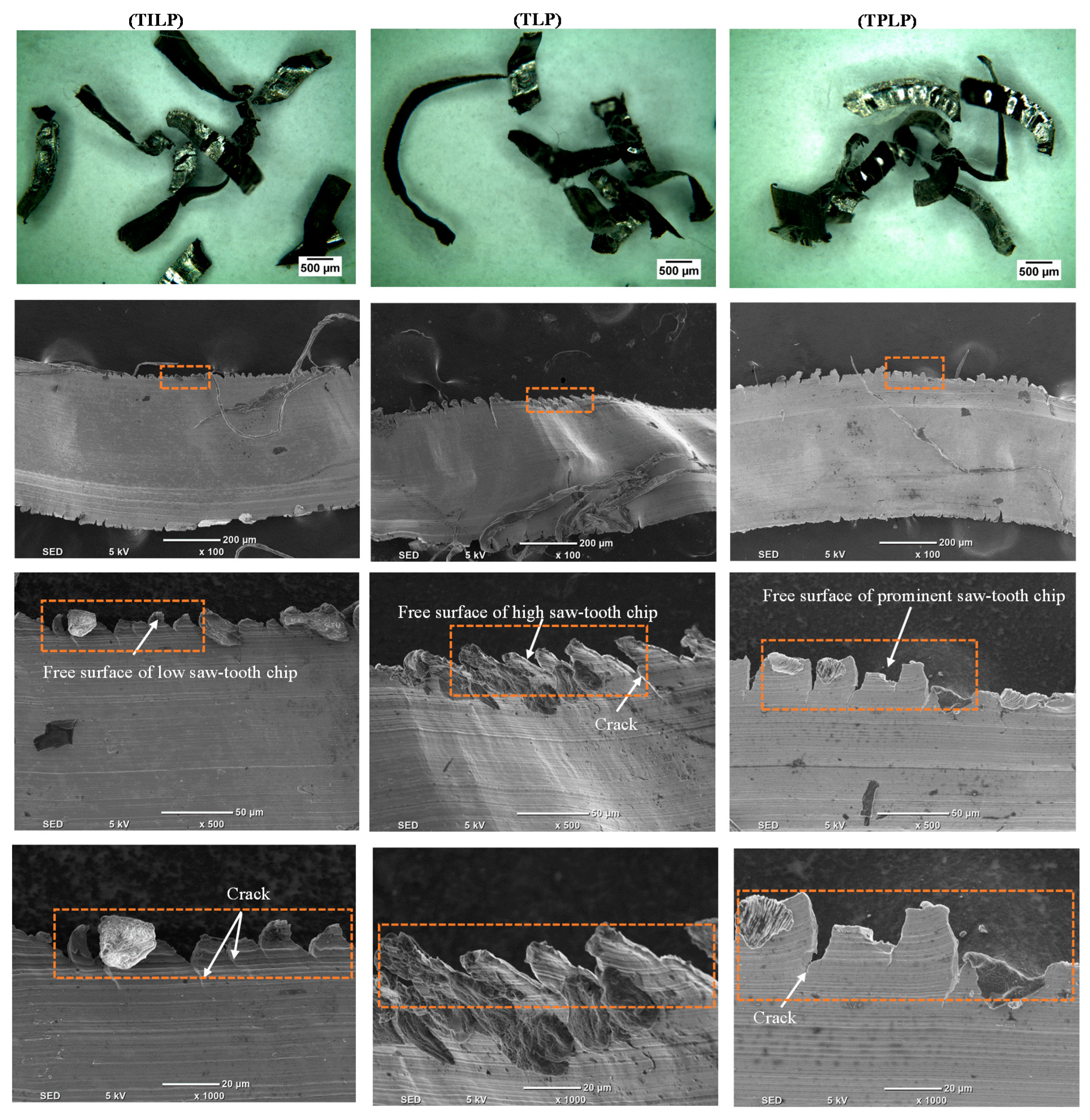
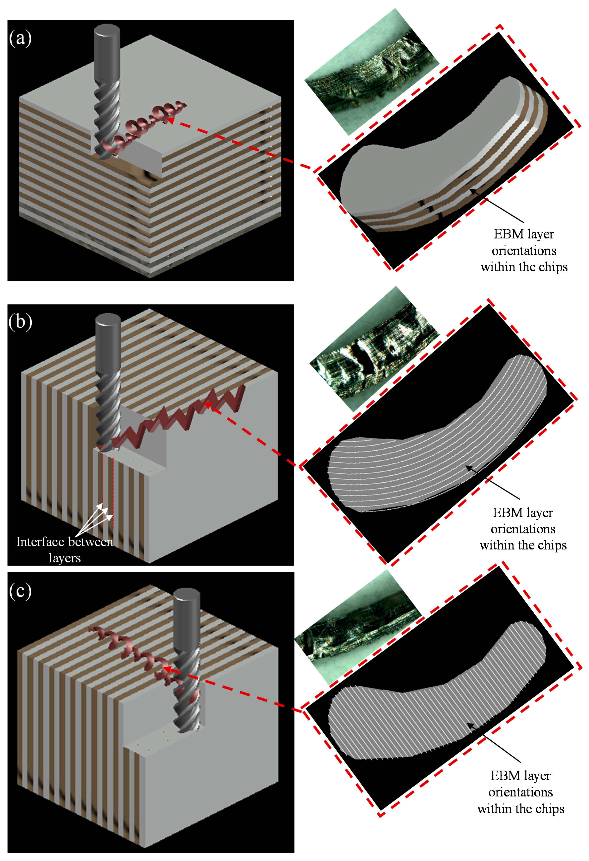
3.6. Chip Morphology Evaluation

Ti6Al4V titanium alloy often generates segmented chips (also called “saw-tooth” chips). These chips affect the cutting forces and temperatures in the machining process, and also the workpiece surface quality as explained in Calamaz et al. [58]. Discontinuous chips are produced during milling of the EBM Ti6Al4V part for three orientations, which are consistent with those found by Al-Rubaie et al. [37] during the milling of the SLM Ti6Al4V part. Chip formation studies are conducted for the three-part orientations at different milling parameters. Figure 13 shows the comparison of the shiny side of the chips that was in contact with the rake face of the tool. The cracks in the chips vary in size and numbers for different orientations of EBM layers. This is because the EBM layers within the chip offer different resistances to chip bending and curling. Therefore, different degrees of cracks are produced for the three orientations. The saw-tooth chips in Figure 13 are much higher for TLP because of the higher cutting forces. Although the tool movement perpendicular to layer planes causes higher saw-tooth chips, it gives a better surface. The saw-tooth chips are less prominent in the TPLP because of the reduced cutting force. The lowest saw-tooth chip height for TILP is also related to the cutting force, which is the lowest for this orientation. In Figure 14, we can see in the case of TILP, the chip formation is low saw-tooth where the machining is performed in the depth of cut 400 µm. In addition, the melting depth of Ti6Al4V powder in a layer during EBM is approximately 50 μm, so the depth of cut approximately encompasses eight EBM layers. The machining is performed in a plane of one layer, which exerts forces on the layer interfaces resulting in the tearing of layers, which cause high roughness. At the same time, in the case of TLP, the chip formation is high saw-tooth (more serrated). This happens because the machining is performed in such a way that both the feed force and the tool rotation put the compressive forces on the layers’ interfaces. This leads to better roughness because no/minimal tearing of layers’ interfaces happened compared with the case of TILP. In the case of TPLP, the saw-tooth pattern on chips and surface roughness are intermediate. This is because the tool rotation (cutting speed) exerts tensile forces, and the feed force exerts buckling load on the interfaces of the layers.

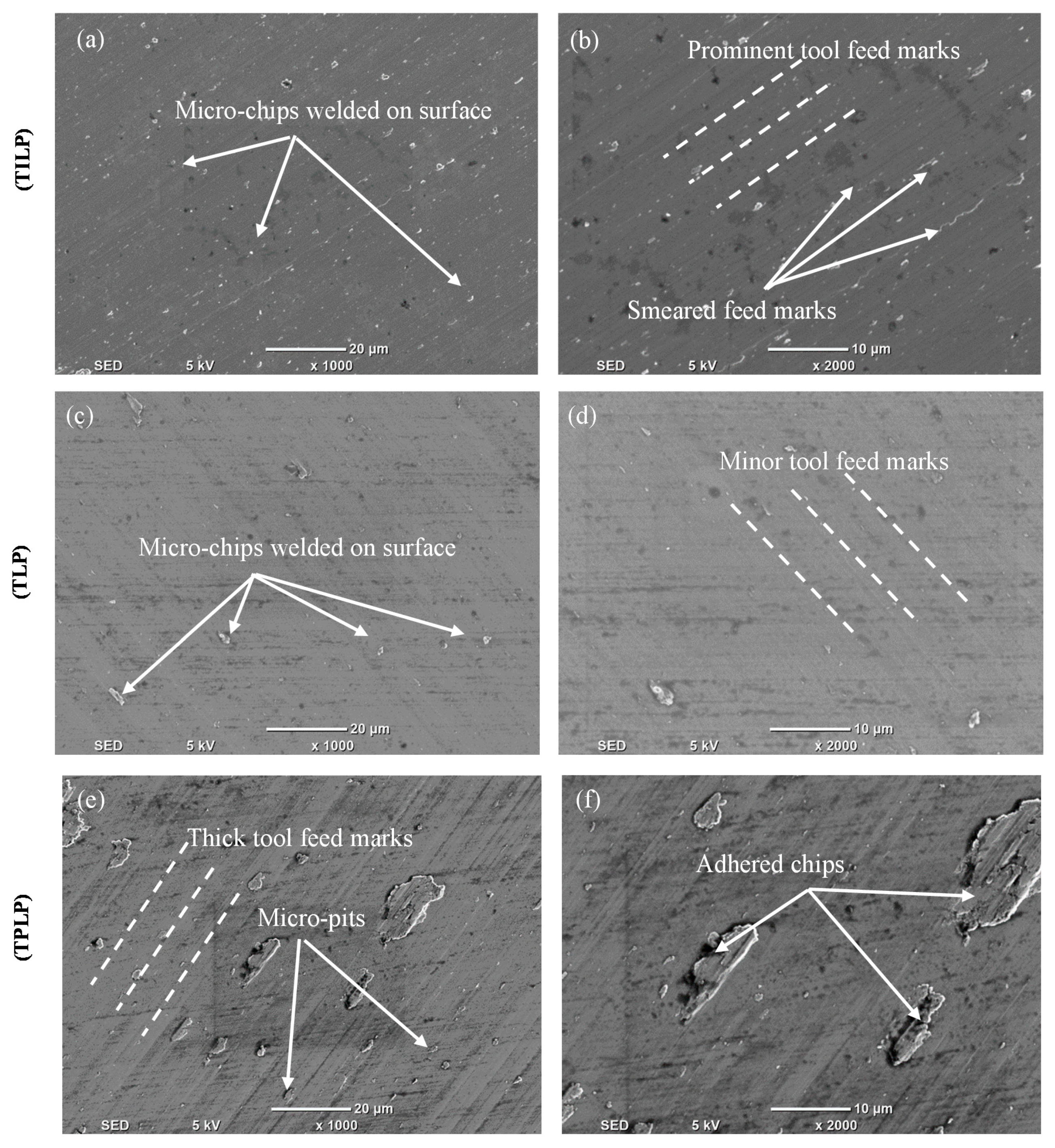
3.7. Surface Morphology of EBM Machined Parts

Figure 15 presents the surface morphology of the EBM parts milled in three-part orientations. The scanning electron micrographs obtained after milling for the three orientations are quite different with regard to tool feed marks, grooves, chips adherence to the milled surfaces, smeared feed marks, and micro-pits generated. For TILP, the EBM spread layers are in-plane to the TFD. The layer thickness of powder melted by the electron beam was set to 50 μm during the Ti6Al4V EBM, while the cutting depth was used at 0.4 mm (400 µm) during the milling process. A tool pass removes around eight layers in this way. However, the layer being cut exerts a tensile load on the underneath layer or layer interface, which deteriorates the surface quality. The effects of the tool feed direction TILP are shown in Figure 15a,b. In this case, smeared feed marks can be seen to impart a large surface roughness (after machining) compared with TLP and TPLP. Furthermore, the feed marks of the tool are more prominent compared with TLP and TPLP. Similar trends are observed for micro-chips adherence and a high number of micro-pits when the EBM parts were milled in the TILP orientation. Therefore, the TILP orientation is not suitable for milling to enhance the surface quality.
In the case of TLP, the interfaces between successive layers are perpendicular to the TFD. The layer interfaces of the multiple layers covered under the radial depth of cut collectively constituted a solid base for milling. The stress distributions and the tool forces were, therefore, more consistent, resulting in a smooth surface texture after machining, as shown in Figure 15c,d. It should also be noted that there is no supporting evidence or micro-pit generation on the machined surface. TLP is, therefore, the most suitable orientation of the component to improve the surface quality.
In the case of TPLP, where the milling tool was moved parallel to layers planes, machining resulted in thick tool feed marks that impart larger roughness on the surface after machining compared to the TLP case. The feed marks are higher than those in the TILP case. The micro-chips’ adherence and the number of micro-pits were high when the EBM parts were machined in the TPLP direction. In this TPLP, the layers stack in parallel with the TFD, and the thickness of a single layer is in the micron range along the build direction. When subjected to the buckling and tensile forces of the milling tool, heterogeneous stresses were subjected to each layer until the material eventually broke and was generated in chip form. Since the ultimate strength of the adjacent layers’ interface may be lower compared to the individual layer strength. Therefore, the mechanical stresses produced by the cutting tool would distribute non-uniformly across the layers. Higher-magnification SEM images (see Figure 15e,f) reveal that in this case, there is clear evidence of both chip adherence and micro-pit clusters that ultimately degrade the surface finish of the Ti6Al4V part. Therefore, the TPLP orientation is also not suitable for milling to improve the surface. TLP is the preferred orientation for finishing purposes. Table 4 summarizes the main surface integrity defects observed on the machined surfaces for the three orientations.

4. Conclusions

In this paper, a study on enhancing the surface quality of the EBM fabricated Ti6Al4V components by using the milling process is presented while considering the different part orientations. It is found that the EBM parts show different machining performance for different part orientations with regard to the tool feed direction even when the same milling conditions are employed. The following main conclusions are drawn from the current work.
(1)
EBM Ti6Al4V parts exhibited significantly higher surface roughness values on the side (Sa = 21 µm) and top faces (Sa = 6 µm) despite using the optimized ARCAM recommended process parameters.
(2)
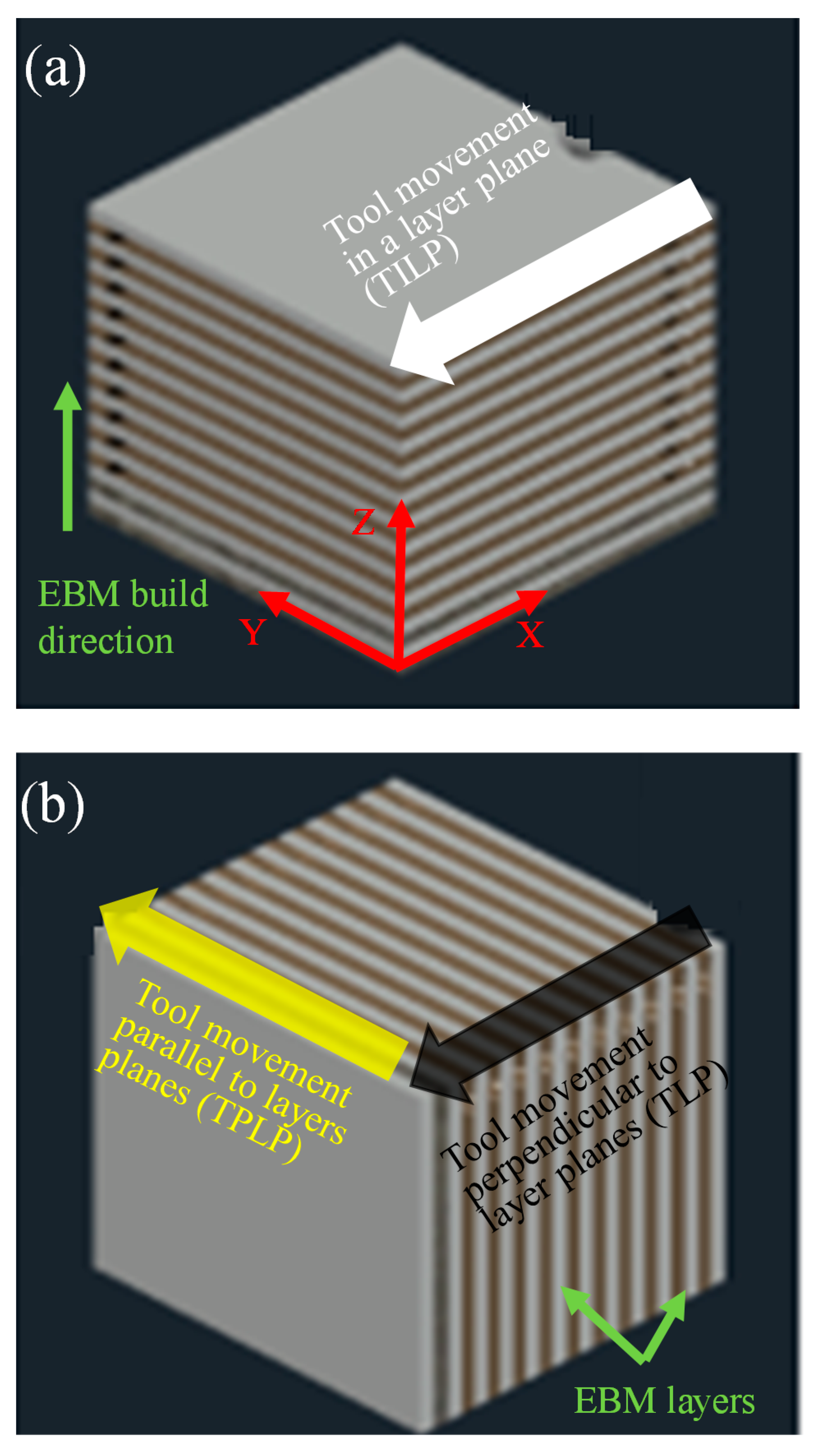
For improving the surface quality, milling was performed on the EBM Ti6Al4V parts in three orientations, namely “tool movement in a layer plane” (TILP), “tool movement perpendicular to layer planes” (TLP), and “tool movement parallel to layers planes” (TPLP).
(3)
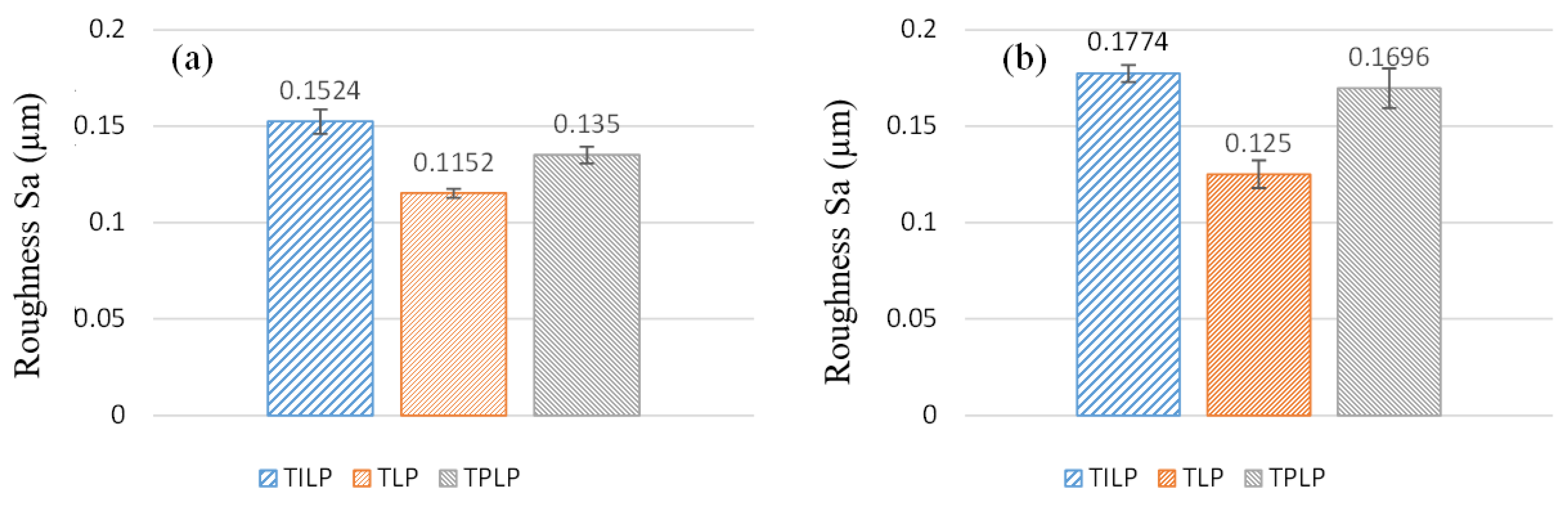
The results showed that considerably lower (improved) surface roughness (Sa = 0.11 µm) was achieved when the milling tool was fed along the TLP orientation as compared to the TILP (Sa = 0.13 µm) and TPLP (Sa = 0.15 µm) orientations, respectively. This is mainly due to the effect of the EBM layers, and α and β grains directionality.
(4)
Regarding the cutting forces, the highest cutting forces were observed when the parts were machined along the TLP orientation. In comparison, the intermediate forces were observed for the TPLP orientation, and the lowest cutting forces were recorded in the case of TILP orientation. For example, at the same milling parameters of V = 80 m/min, f = 30 mm/min, and dR = 4.8 mm, the cutting force in the case of TLP was 114 N, which was 42% and 57% higher compared to the forces recorded for TPLP and TILP orientations, respectively.
(5)
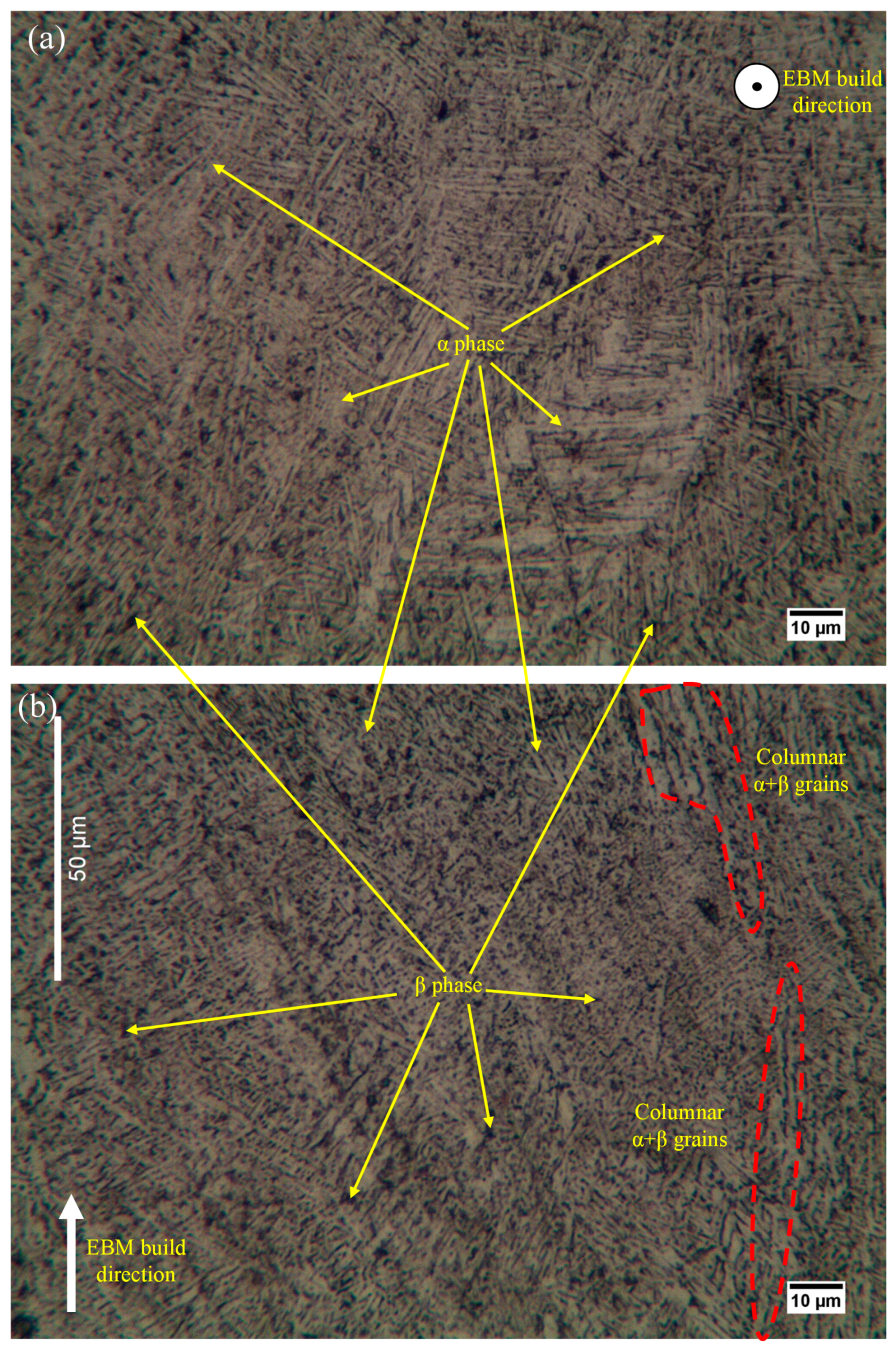
It was observed that the extent of the deformed microstructure beneath the machined surface varies for different part orientations. The highest depth of the deformation was found in the case of the TLP and then for TPLP, and the lowest deformation was found in the case of TILP. These results were in line with the trend of the cutting forces, i.e., the higher the cutting force produced more deformed microstructure. The increase in the sub-surface microhardness also followed the same trend as the deformation in the microstructure.
(6)
Regarding the chip formation, TLP produced the highest saw-tooth chips because of the large cutting force, followed by TPLP and then TILP.
(7)
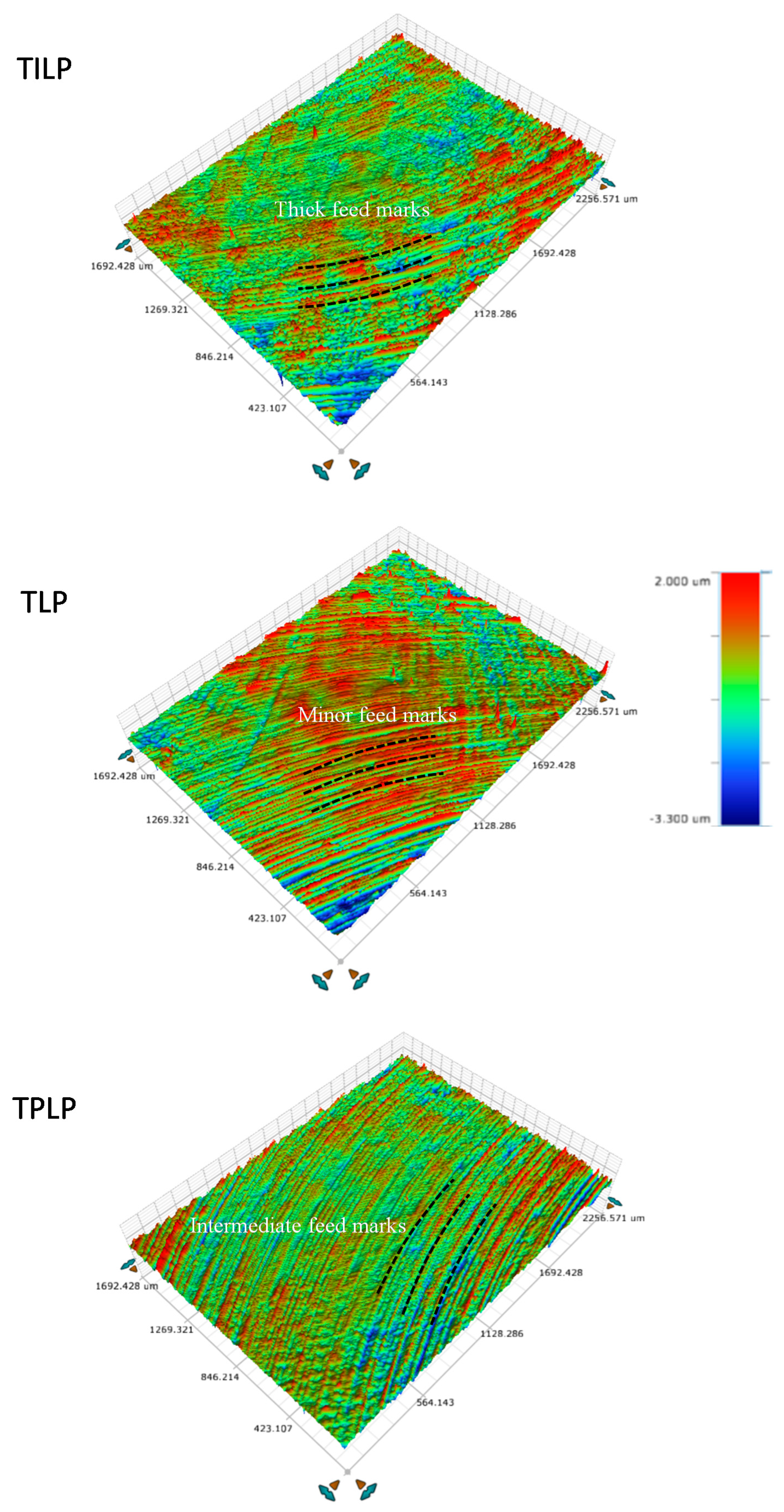
The surface morphology of the machined parts showed grooves, smeared feed marks, micro-chips deposition, micro-pits, and tool feed marks, which were minimum in the case of TLP.

Author Contributions

Conceptualization, A.D. and S.A.; methodology, A.D.; validation, A.D., S.A., and M.M.N.; formal analysis, A.D.; investigation, A.D., S.A., and M.M.N.; data curation, A.D. and S.A.; writing—original draft preparation, A.D.; writing—review and editing, A.D., S.A., and A.M.A.-S.; visualization, A.D.; supervision, S.A. and A.M.A.-S. All authors have read and agreed to the published version of the manuscript.

Funding

The authors extend their appreciation to the Deanship of Scientific Research at King Saud University for funding this work through research group no. RG-1438-088.

Acknowledgments

The authors thank the Deanship of Scientific Research and RSSU at King Saud University for technical support.

Conflicts of Interest

The authors declare no conflict of interest.

References

  1. Wally, Z.J.; van Grunsven, W.; Claeyssens, F.; Goodall, R.; Reilly, G.C. Porous titanium for dental implant applications. Metals 2015, 5, 1902–1920. [Google Scholar] [CrossRef]
  2. Iqbal, A.; Suhaimi, H.; Zhao, W.; Jamil, M.; Nauman, M.M.; He, N.; Zaini, J. Sustainable Milling of Ti-6Al-4V: Investigating the effects of milling orientation, cutter′s helix angle, and type of cryogenic coolant. Metals 2020, 10, 258. [Google Scholar] [CrossRef] [Green Version]
  3. Schulz, H.; Annals, T.M.-C. High-speed machining. CIRP Ann.-Manuf. Technol. 1992, 41, 637–643. [Google Scholar] [CrossRef]
  4. Ezugwu, E.; Bonney, J.; Yamane, Y. An overview of the machinability of aeroengine alloys. J. Mater. Process. Technol. 2003, 134, 233–253. [Google Scholar] [CrossRef]
  5. Sharif, S. EA Rahim Performance of coated-and uncoated-carbide tools when drilling titanium alloy—Ti–6Al4V. J. Mater. Process. Technol. 2007, 185, 72–76. [Google Scholar] [CrossRef] [Green Version]
  6. Safari, H.; Sharif, S.; Izman, S.; Jafari, H.; Kurniawan, D. Cutting force and surface roughness characterization in cryogenic high-speed end milling of Ti–6Al-4V ELI. Mater. Manuf. Process. 2014, 29, 350–356. [Google Scholar] [CrossRef]
  7. Additive Manufacturing for the Aerospace Industry—Google Books. Available online: https://books.google.com.sa/books?hl=en&lr=&id=IlSIDwAAQBAJ&oi=fnd&pg=PP1&dq=Additive+manufacturing+for+aerospace+industry&ots=BAIj8xFuVn&sig=t5np9Q3NDRF8-ws8NJRZSFbkfiA&redir_esc=y#v=onepage&q=Additivemanufacturingforaerospaceindustry&f=false (accessed on 22 August 2020).
  8. Hassanin, H.; Finet, L.; Cox, S.C.; Jamshidi, P.; Grover, L.M.; Shepherd, D.E.T.; Addison, O.; Attallah, M.M. Tailoring selective laser melting process for titanium drug-delivering implants with releasing micro-channels. Addit. Manuf. 2018, 20, 144–155. [Google Scholar] [CrossRef] [Green Version]
  9. Layer by Layer|MIT Technology Review. Available online: https://www.technologyreview.com/2011/12/19/20869/layer-by-layer/ (accessed on 22 August 2020).
  10. An Epiphany Of Disruption: GE Additive Chief Explains How 3D Printing Will Upend Manufacturing|GE News. Available online: https://www.ge.com/news/reports/epiphany-disruption-ge-additive-chief-explains-3d-printing-will-upend-manufacturing (accessed on 22 August 2020).
  11. A World First: Additively Manufactured Titanium Components Now Onboard the Airbus A350 XWB. Available online: https://www.etmm-online.com/a-world-first-additively-manufactured-titanium-components-now-onboard-the-airbus-a350-xwb-a-486310/ (accessed on 22 August 2020).
  12. Maloney, K.J.; Fink, K.D.; Schaedler, T.A.; Kolodziejska, J.A.; Jacobsen, A.J.; Roper, C.S. Multifunctional heat exchangers derived from three-dimensional micro-lattice structures. Int. J. Heat Mass Transf. 2012, 55, 2486–2493. [Google Scholar] [CrossRef]
  13. Ngo, T.D.; Kashani, A.; Imbalzano, G.; Nguyen, K.T.Q.; Hui, D. Additive manufacturing (3D printing): A review of materials, methods, applications and challenges. Compos. Part B Eng. 2018, 143, 172–196. [Google Scholar] [CrossRef]
  14. Heinl, P.; Müller, L.; Körner, C.; Singer, R.F.; Müller, F.A. Cellular Ti-6Al-4V structures with interconnected macro porosity for bone implants fabricated by selective electron beam melting. Acta Biomater. 2008, 4, 1536–1544. [Google Scholar] [CrossRef]
  15. Harrysson, O.L.A.; Cormier, D.R.; Marcellin-Little, D.J.; Jajal, K. Rapid prototyping for treatment of canine limb deformities. Rapid Prototyp. J. 2003, 9, 37–42. [Google Scholar] [CrossRef]
  16. Parthasarathy, J.; Starly, B.; Raman, S.; Christensen, A. Mechanical evaluation of porous titanium (Ti6Al4V) structures with electron beam melting (EBM). J. Mech. Behav. Biomed. Mater. 2009, 3, 249–259. [Google Scholar] [CrossRef] [PubMed]
  17. Ameen, W.; Khan Mohammed, M.; Al-Ahmari, A. Evaluation of support structure removability for additively manufactured Ti6Al4V overhangs via electron beam melting. Metals 2019, 9, 1211. [Google Scholar] [CrossRef] [Green Version]
  18. Dolimont, A.; Michotte, S.; Rivière-Lorphèvre, E.; Ducobu, F.; Vivès, S.; Godet, S.; Henkes, T.; Filippi, E. Influence on surface characteristics of electron beam melting process (EBM) by varying the process parameters. AIP Conf. Proc. 2017, 1896, 040010. [Google Scholar] [CrossRef] [Green Version]
  19. Safdar, A.; He, H.Z.; Wei, L.Y.; Snis, A.; Chavez De Paz, L.E. Effect of process parameters settings and thickness on surface roughness of EBM produced Ti-6Al-4V. Rapid Prototyp. J. 2012, 18, 401–408. [Google Scholar] [CrossRef]
  20. Wang, P.; Sin, W.J.; Nai, M.L.S.; Wei, J. Effects of processing parameters on surface roughness of additive manufactured Ti-6Al-4V via electron beam melting. Materials 2017, 10, 1121. [Google Scholar] [CrossRef] [Green Version]
  21. Greitemeier, D.; Dalle Donne, C.; Syassen, F.; Eufinger, J.; Melz, T. Effect of surface roughness on fatigue performance of additive manufactured Ti–6Al–4V. Mater. Sci. Technol. 2016, 32, 629–634. [Google Scholar] [CrossRef]
  22. Wennerberg, A.; Albrektsson, T. Effects of titanium surface topography on bone integration: A systematic review. Clin. Oral Implant. Res. 2009, 20, 172–184. [Google Scholar] [CrossRef]
  23. Ramesh, S.; Karunamoorthy, L.; Palanikumar, K. Measurement and analysis of surface roughness in turning of aerospace titanium alloy (gr5). Meas. J. Int. Meas. Confed. 2012, 45, 1266–1276. [Google Scholar] [CrossRef]
  24. Masuo, H.; Tanaka, Y.; Morokoshi, S.; Yagura, H.; Uchida, T.; Yamamoto, Y.; Murakami, Y. Effects of Defects, Surface Roughness and HIP on Fatigue Strength of Ti-6Al-4V manufactured by Additive Manufacturing. Procedia Struct. Integr. 2017, 7, 19–26. [Google Scholar] [CrossRef]
  25. Anwar, S.; Ahmed, N.; Abdo, B.M.; Pervaiz, S.; Chowdhury, M.A.K.; Alahmari, A.M. Electron beam melting of gamma titanium aluminide and investigating the effect of EBM layer orientation on milling performance. Int. J. Adv. Manuf. Technol. 2018, 96, 3093–3107. [Google Scholar] [CrossRef]
  26. Biffi, C.A.; Fiocchi, J.; Ferrario, E.; Fornaci, A.; Riccio, M.; Romeo, M.; Tuissi, A. Effects of the scanning strategy on the microstructure and mechanical properties of a TiAl6V4 alloy produced by electron beam additive manufacturing. Int. J. Adv. Manuf. Technol. 2020, 107, 4913–4924. [Google Scholar] [CrossRef]
  27. Kumar, M.; Kumar, A.; Ji, H.; Song, Q.; Liu, Z.; Cai, W.; Mia, M.; Khanna, N. Impact of layer rotation on micro-structure, grain size, surface integrity and mechanical behaviour of SLM Al-Si-10Mg alloy. Integr. Med. Res. 2020, 9, 9506–9522. [Google Scholar] [CrossRef]
  28. Hassanin, H.; Essa, K.; Qiu, C.; Abdelhafeez, A.M.; Adkins, N.J.E.; Attallah, M.M. Net-shape manufacturing using hybrid selective laser melting/hot isostatic pressing. Rapid Prototyp. J. 2017, 4, 720–726. [Google Scholar] [CrossRef] [Green Version]
  29. Qiu, C.; Adkins, N.J.E.; Hassanin, H.; Attallah, M.M.; Essa, K. In-situ shelling via selective laser melting: Modelling and microstructural characterisation. Mater. Des. 2015, 87, 845–853. [Google Scholar] [CrossRef]
  30. Sun, J.; Guo, Y.B. A comprehensive experimental study on surface integrity by end milling Ti-6Al-4V. J. Mater. Process. Technol. 2009, 209, 4036–4042. [Google Scholar] [CrossRef]
  31. Milton, S.; Morandeau, A.; Chalon, F.; Leroy, R. Influence of finish machining on the surface integrity of ti6al4v produced by selective laser melting. Procedia CIRP 2016, 45, 127–130. [Google Scholar] [CrossRef] [Green Version]
  32. Bordin, A.; Bruschi, S.; Ghiotti, A.; Bucciotti, F.; Facchini, L. Comparison between wrought and EBM Ti6Al4V machinability characteristics. Key Eng. Mater. 2014, 611–612, 1186–1193. [Google Scholar] [CrossRef]
  33. Koike, M.; Greer, P.; Owen, K.; Lilly, G.; Murr, L.E.; Gaytan, S.M.; Martinez, E.; Okabe, T. Evaluation of titanium alloys fabricated using rapid prototyping technologies—Electron beam melting and laser beam melting. Materials 2011, 4, 1776–1792. [Google Scholar] [CrossRef]
  34. Zhang, W.; Qin, P.; Wang, Z.; Yang, C.; Kollo, L.; Grzesiak, D.; Prashanth, K.G. Superior wear resistance in EBM-Processed TC4 alloy compared with SLM and forged samples. Materials 2019, 12, 782. [Google Scholar] [CrossRef] [Green Version]
  35. Ginta, T.L. Development of surface roughness models in end milling titanium alloy Ti-6Al-4V Using uncoated tungsten carbide inserts. Eur. J. Sci. Res. 2009, 28, 542–551. [Google Scholar]
  36. Zhang, S.; Li, J. Tool wear criterion, tool life, and surface roughness during high-speed end milling Ti-6Al-4V alloy. J. Zhejiang Univ.-Sci. A 2010, 11, 587–595. [Google Scholar] [CrossRef]
  37. Al-rubaie, K.S.; Melotti, S.; Rabelo, A.; Paiva, J.M. Machinability of SLM-produced Ti6Al4V titanium alloy parts. J. Manuf. Process. 2020, 57, 768–786. [Google Scholar] [CrossRef]
  38. Thesiya, D.; Rajurkar, A.; Patel, S. Heat affected zone and recast layer of Ti-6Al-4V alloy in the EDM process through scanning electron microscopy (SEM). J. Manuf. Technol. Res. 2014, 6, 1–2. [Google Scholar]
  39. Bruschi, S.; Bertolini, R.; Bordin, A.; Medea, F.; Ghiotti, A. Influence of the machining parameters and cooling strategies on the wear behavior of wrought and additive manufactured Ti6Al4V for biomedical applications. Tribol. Int. 2016, 102, 133–142. [Google Scholar] [CrossRef]
  40. Bordin, A.; Sartori, S.; Bruschi, S.; Ghiotti, A. Experimental investigation on the feasibility of dry and cryogenic machining as sustainable strategies when turning Ti6Al4V produced by Additive Manufacturing. J. Clean. Prod. 2017, 142, 4142–4151. [Google Scholar] [CrossRef]
  41. Al-Ahmari, A.; Ashfaq, M.; Alfaify, A.; Abdo, B.; Alomar, A.; Dawud, A. Predicting surface quality of γ-TiAl produced by additive manufacturing process using response surface method. J. Mech. Sci. Technol. 2016, 30, 345–352. [Google Scholar] [CrossRef]
  42. Kyzioł, K.; Kaczmarek, Ł.; Brzezinka, G.; Kyzioł, A. Structure, characterization and cytotoxicity study on plasma surface modified Ti-6Al-4V and γ-TiAl alloys. Chem. Eng. J. 2014, 240, 516–526. [Google Scholar] [CrossRef]
  43. Ameen, W.; Al-Ahmari, A.; Mohammed, M.K. Self-supporting overhang structures produced by additive manufacturing through electron beam melting. Int. J. Adv. Manuf. Technol. 2019, 104, 2215–2232. [Google Scholar] [CrossRef]
  44. Umer, U.; Ameen, W.; Abidi, M.H.; Moiduddin, K.; Alkhalefah, H.; Alkahtani, M.; Al-Ahmari, A. Modeling the effect of different support structures in electron beam melting of titanium alloy using finite element models. Metals 2019, 9, 806. [Google Scholar] [CrossRef] [Green Version]
  45. Ameen, W.; Al-Ahmari, A.; Mohammed, M.K.; Abdulhameed, O.; Umer, U.; Moiduddin, K. Design, finite element analysis (FEA), and fabrication of custom titanium alloy cranial implant using electron beam melting additive manufacturing. Adv. Prod. Eng. Manag. 2018, 13, 267–278. [Google Scholar] [CrossRef] [Green Version]
  46. Liu, H.; Wu, C.; Phenomena, R.C.-S.S. Effects of cutting parameters on the surface roughness of Ti6Al4V titanium alloys in side milling. In Solid State Phenomena; Trans Tech Publications Ltd.: Xiamen, China, 2011; Volume 175, pp. 289–293. [Google Scholar]
  47. Oosthuizen, G.A.; Nunco, K.; Conradie, P.J.T.; Dimitrov, D.M. The effect of cutting parameters on surface integrity in milling TI6AL4V. S. Afr. J. Ind. Eng. 2016, 27, 115–123. [Google Scholar] [CrossRef] [Green Version]
  48. Wu, H.; Zhang, S. Effects of cutting conditions on the milling process of titanium alloy Ti6Al4V. Int. J. Adv. Manuf. Technol. 2015, 77, 2235–2240. [Google Scholar] [CrossRef]
  49. Todai, M.; Nakano, T.; Liu, T.; Yasuda, H.Y.; Hagihara, K.; Cho, K.; Ueda, M.; Takeyama, M. Effect of building direction on the microstructure and tensile properties of Ti-48Al-2Cr-2Nb alloy additively manufactured by electron beam melting. Addit. Manuf. 2017, 13, 61–70. [Google Scholar] [CrossRef] [Green Version]
  50. Mohammadhosseini, A.; Fraser, D.; Masood, S.H.; Jahedi, M. Microstructure and mechanical properties of Ti-6Al-4V manufactured by electron beam melting process. Mater. Res. Innov. 2013, 17. [Google Scholar] [CrossRef]
  51. Lenz, M. 1. Introduction. In Arms Are Necessary; Böhlau Verlag: Köln, Germany, 2010; pp. 1–20. [Google Scholar] [CrossRef]
  52. Galarraga, H.; Lados, D.A.; Dehoff, R.R.; Kirka, M.M.; Nandwana, P. Effects of the microstructure and porosity on properties of Ti-6Al-4V ELI alloy fabricated by electron beam melting (EBM). Addit. Manuf. 2016, 10, 47–57. [Google Scholar] [CrossRef] [Green Version]
  53. Al-Bermani, S.S.; Blackmore, M.L.; Zhang, W.; Todd, I. The origin of microstructural diversity, texture, and mechanical properties in electron beam melted Ti-6Al-4V. Metall. Mater. Trans. A Phys. Metall. Mater. Sci. 2010, 41, 3422–3434. [Google Scholar] [CrossRef]
  54. Raghavan, S.; Ling, M.; Nai, S.; Wang, P.; Sin, W.J.; Li, T.; Wei, J. Heat treatment of electron beam melted (EBM) Ti-6Al-4V: Microstructure to mechanical property correlations. Rapid Prototyp. J. 2018, 24, 774–783. [Google Scholar] [CrossRef]
  55. Wang, F.; Zhao, J.; Li, A.; Zhao, J. Cutting forces and surface roughness in high-speed end milling of Ti6Al4V. Key Eng. Mater. 2014, 589–590, 76–81. [Google Scholar] [CrossRef]
  56. Galarraga, H.; Warren, R.J.; Lados, D.A.; Dehoff, R.R.; Kirka, M.M.; Nandwana, P. Effects of heat treatments on microstructure and properties of Ti-6Al-4V ELI alloy fabricated by electron beam melting (EBM). Mater. Sci. Eng. A 2017, 685, 417–428. [Google Scholar] [CrossRef] [Green Version]
  57. Qiu, C.; Adkins, N.J.E.; Attallah, M.M. Microstructure and tensile properties of selectively laser-melted and of HIPed laser-melted Ti-6Al-4V. Mater. Sci. Eng. A 2013, 578, 230–239. [Google Scholar] [CrossRef]
  58. Calamaz, M.; Coupard, D.; Girot, F. A new material model for 2D numerical simulation of serrated chip formation when machining titanium alloy Ti-6Al-4V. Int. J. Mach. Tools Manuf. 2008, 48, 275–288. [Google Scholar] [CrossRef] [Green Version]
Figure 1. 3D part fabricated through electron beam melting (EBM).
Metals 10 01172 g001
Figure 2. A schematic representation of EBM part orientation options for milling: (a) Top face; (b) Side face.
Metals 10 01172 g002
Figure 3. (a) Machining process setup of the part fabricated by EBM; (b) Machined part enlarged view with labeled various orientations.
Metals 10 01172 g003
Figure 4. SEM scanned surfaces of as fabricated EBM part: (a) Top face, X-Y axes represents the powder bed plane; (b) Side face, Z-axis shows the EBM build direction.
Metals 10 01172 g004
Figure 5. Optical microscope images of the as-fabricated EBM-produced sample: (a) Top face; (b) Side face. (The vertical scale is provided for the indication of the EBM layer thickness).
Metals 10 01172 g005
Figure 6. Surface roughness measured for TILP, TLP, and TPLP orientations at (a) cutting speed (V) = 80 m/min, feed rate (f) = 30 mm/min and radial depth (dR) = 4.8 mm, and (b) cutting speed (V) = 80 m/min, feed rate (f) = 30 mm/min and radial depth (dR) = 2.4 mm. The error bars represent ±1σ.
Metals 10 01172 g006
Figure 7. 3D scanned surfaces roughness profiles for the three part orientations at cutting speed (V) = 80 m/min, feed rate (f) = 30 mm/min and radial depth (dR) = 4.8 mm.
Metals 10 01172 g007
Figure 8. 2D roughness profiles for the three part orientations at cutting speed (V) = 80 m/min, feed rate (f) = 30 mm/min and radial depth (dR) = 4.8 mm.
Metals 10 01172 g008
Figure 9. Ff, Fr and Fa forces for the three orientations recorded while machining at: (a) cutting speed (V) = 80 m/min, feed rate (f) = 30 mm/min, and radial depth (dR) = 4.8 mm; (b) cutting speed (V) = 50 m/min, feed rate (f) = 60 mm/min, and radial depth (dR) = 4.8 mm. The error bars represents ±1σ.
Metals 10 01172 g009
Figure 10. Schematic view of lamellar and columnar α + β grains and tool feed direction: (a) Side face; (b) Top face.
Metals 10 01172 g010
Figure 11. Effects of milling process on subsurface microstructure of layer orientations for: (a) TILP; (b) TLP; (c) TPLP at cutting speed (V) = 80 m/min, feed rate (f) = 30 mm/min and radial depth (dR) = 4.8 mm.
Metals 10 01172 g011
Figure 12. (a) A view of Vickers micro-indentation; (b) Micro-hardness recorded for the three orientations on the machined surface at cutting speed (V) = 80 m/min, feed rate (f) = 30 mm/min and radial depth (dR) = 4.8 mm. The error bars represent ±1σ.
Metals 10 01172 g012
Figure 13. Chip morphology for different orientations at cutting speed (V) = 80 m/min, feed rate (f) = 30 mm/min and radial depth (dR) = 2.4 mm.
Metals 10 01172 g013
Figure 14. Schematic view for the part orientations effect on the chips formation: (a) TILP; (b) TLP; (c) TPLP.
Metals 10 01172 g014
Figure 15. Milled surface images for orientations: (a,b) TILP; (c,d) TLP; (e,f) TPLP using SEM at cutting speed (V) = 80 m/min, feed rate (f) = 30 mm/min and radial depth (dR) = 2.4 mm.
Metals 10 01172 g015
Table 1. Chemical composition of Ti6Al4V powder [45].
Chemical ElementContent in (%)
Aluminum6.04
Vanadium4.05
Carbon0.013
Iron0.0107
Oxygen0.13
TitaniumBalance/Base
Table 2. EBM parameters for Ti6Al4V parts [43,44].
EBM ParametersValues
Beam current15 mA
Electron beam diameter200 μm
Acceleration voltage60 kV
Focus offset3 mA
Line offset0.1 Mm
Scan speed4530 mm/s
Powder layer thickness0.05 mm
Liquidus temperature1928 K
Preheat temperature750 °C
Solidus temperature1878 K
Table 3. Details of the milling parameters.
Process ParametersValues
Feed rate, (f) mm/min30, 60
Radial depth of cut, (dR) mm2.4, 4.8
Depth of cut, (d) mm0.4
Cutting speed, (V) m/min50, 80
Tool feed direction, (TFD)TLP, TPLP, TILP
Table 4. Key occurrence of defects in the tested samples. Incidence scale: ○ = marginal, ● = weak, ●● = moderate, ●●● = large.
DefectsTILPTLPTPLP
Adhered material●●●●●
Grooves●●●●●
Smeared feed marks●●●
Micro-chips welded on the surface●●●●●
Micro-pits●●●●●
Thick tool feed marks●●●●●

