Article

On Additive Manufactured AlSi10Mg to Wrought AA6060-T6: Characterisation of Optimal- and High-Energy Magnetic Pulse Welding Conditions

1
Department of Materials, Nuclear Research Center-Negev, Beer Sheva 8410900, Israel
2
Department of Materials Engineering, Ben-Gurion University of the Negev, Beer Sheva 8410501, Israel
3
Bmax Srl., Hod Hasharon 4501306, Israel
4
School of Mechanical Engineering, Tel Aviv University, Ramat Aviv 6997801, Israel
5
Department of Mechanical Engineering, Afeka Academic College of Engineering, Tel Aviv 6910717, Israel
*
Author to whom correspondence should be addressed.
Metals 2020, 10(9), 1235; https://doi.org/10.3390/met10091235
Submission received: 23 August 2020 / Revised: 9 September 2020 / Accepted: 11 September 2020 / Published: 14 September 2020

Abstract

:
This novel research aims to examine the macro and microstructural bonding region development during magnetic pulse welding (MPW) of dissimilar additive manufactured (AM) laser powder-bed fusion (L-PBF) AlSi10Mg rod and AA6060-T6 wrought tube, using both optimal- and high-energy welding conditions. For that purpose, various joint characterisation methods were applied. It is demonstrated that high-quality hermetic welds are achievable with adjusted MPW process parameters. The macroscale analysis has shown that the joint interfaces are deformed to a waveform shape; the interface is starting relatively planar, with waves forming and growing in the welding direction. The observed thickening of the flyer’s wall after welding is the result of its diametral inward deformation, taking place during the process. A slight increase in microhardness was adjacent to the faying interfaces; a higher increase was measured on the AlSi10Mg material side, while a smaller one was observed on the AA6060 side. Along the wavy interfaces, resolidified “pockets” of material or occasionally discontinuous short layers exhibiting different morphologies, were detected. The jet residues are typically located towards the end of the weld, confirming a temperature rise that exceeds the melting temperature of both alloys. Far from the weld zone, extremely thin-film deposits were clearly observed on the inner flyer surfaces. The formation of isolated Si particles and thin-film deposits may point out that the local increase in temperatures leads to melting or even evaporation vaporisation of superficial layers from the colliding parts. It is worth noting that this type of jet residue was discovered for the first time in the present research. The current research work is expected to provide an understanding of weld formation mechanisms of additively manufactured parts to conventional wrought parts conforming to existing wrought/wrought weld knowledge.

1. Introduction

Joining by welding plays an important role in the fabrication of mechanical assemblies created from parts with different properties. Explosive welding, gas gun welding, laser impact welding, vaporising foil actuator welding, and magnetic pulse welding (MPW) are the five main joining techniques based on impact phenomena proven to date. For example, Bataev and his colleagues [1] studied explosion-welded steel plates; for this purpose, they used the hydrodynamics of particles for simulating the plastic deformation and generated heat. Lee et al. [2] reported the effect of internal stress waves in vaporising foil actuator welding, using Cu-110 as the stationary part and constant thickness CP-Ti flyers. Experiments and simulations show that increasing target thickness leads to the increasing interfacial wavelength. Flyer velocity and wavy interface morphology were also studied. Nassiri et al. [3] studied solid-state welding processes by combined numerical simulations, diffusion calculations, and interfacial characterisation techniques. Determination of the relations between the development of defects within the joining area and melting phenomena was concluded.
In the last decade, special attention has been focused towards the technologies of dissimilar welding and joining processes [4,5]. Stern et al. [6] studied the microstructure development of the joining zone in MPW of similar and dissimilar workpieces. A continuous transition region or a disrupted “pocket” type zone along the weld interface is explained in terms of limited-area melting followed by rapid solidification. A noteworthy hardness increase was detected at the interface layer. Stern and his colleagues [7] investigated the molten welding pool during the MPW of Al/Mg couples. They concluded that the temperature of the welding zone was locally greater than the melting points of Al and Mg, thus forming molten regions. They found that the fusion zone contains equivalent amounts of both Al and Mg. The MPW method is based on flyer acceleration and collision attained through magnetic pressure, formed by the rapid discharge of a capacitor bank through a tool-coil, located adjacent to the flyer (Figure 1).
In the initial state, the to-be-joined components (a movable flyer and a stationary part) are positioned at a standoff, which defines the acceleration distance. Lorentz forces created by the eddy currents induced into the flyer, drive the flyer away from the coil towards the stationary component. The imposed plastic deformation and interface pressures of approximately several GPa, taking place for several microseconds, create the MP joint. The hydrodynamic phenomena occurring at the propagating collision zone are expected to eject a jet, containing surface materials, gases, and contaminants, while bringing the faying virgin surfaces into intimate contact. Kakizaki et al. [8] investigated the jet emission and the weld interface of similar and dissimilar metals. Numerical simulation of oblique collision between plates was made for various thicknesses, velocities, and angles. The composition of the jet was ruled by the degree of density difference between the two metals. For example, in cases of large density differences, the jet mainly contained the metal element with lower density.
Stern et al. [9] studied the composition of the jet emitted in MP welding utilized on similar and dissimilar metal lap joints: Al/Al and Al/Mg welds. The composition of the jet remnants was governed by the density difference of the two components, as mentioned above [8]. The estimated thickness of the films peeled in the MPW process was also calculated; an average thickness of 17 µm was evaluated for the Al-Al pair and for Al-Mg pairs the values were of about 10 µm. Wang and his colleagues [10] investigated explosive/impact welding, to expand the understanding of the aspects that govern the quality of explosive-welded joints. The phenomenon of jetting and the interfacial waves detected in explosive welding were quite well replicated in the simulations. The jets are typically described as a mixture of materials from the flyer and stationary parts, their oxides, gases present in the closing gap, and other surface contaminants. The occurrence of jet phenomenon has been proven by trapping accumulated ejected materials [9], by numerical analysis [10], and by simulation of the MPW process. Ejected material may be in the form of solid debris; however, the ejection phenomena can also occur as fluid jetting when the temperature exceeds the melting temperature of the materials at the interface. The fragments from the interface are usually observed near the end of the weld zone and at the inner faying surfaces. The impact of thermal effects occurring at the interface in the course of MPW, such as local melting, has been brought into focus by numerous scholars, pointing to the identification of the major joining phenomena/mechanisms. Bellmann et al. [11] estimated the typical high velocity impact flash during MPW, using phototransistors, with the purpose of impact’s time measurement. The outcomes are in good agreement with the well-known PDV (photon Doppler velocimetry) demonstrating good repeatability; for example, Lueg-Althoff and his colleagues [12] showed “that the minimum radial impact velocity required for welding with the same geometrical setup can be reduced significantly at low discharge frequencies compared to high one”. Pourabbas et al. [13] studied the MPW of AA4014 to AA7075 and found that variety of welding parameters were carefully chosen to acquire acceptable welds. In addition, three modes of welding interfaces with wavy, molten wavy, and porous morphologies were detected. Of the three, welding with the wavy morphology showed the maximum mechanical strength.
A short flash was visible for all successful MPW runs; it looks like the shock compression of the gas present in between the components is the source of the instant light emission. The hydrodynamic flow of material ejects superficial layers of both parts from the closing gap, as demonstrated by Shribman et al. [14], and that the jet that was ejected was formed from the welded faying faces of both workpieces, confirmed by Stern et al. [9]. The jet formation cleans and activates the metal surfaces prior to welding and leaves them chemically pure, preferring the establishment of metallic bonds under the prevailing interface pressure. Many of the latest MPW studies have shown evidence of melted and rapidly cooled regions along the joint interface, e.g., amorphous structures that can be attributed to rapid solidification with cooling rates in the magnitude of 107 K·s−1. Recrystallised nanometric grain size, as well as localised melting in the range of micron-sized “pockets” were observed by several studies [3,7,15,16,17]. Bellmann et al. [18] examined the cloud of CoP particles, which is expelled as an outcome of the high-speed impact between the two metals. MPW tests were performed in vacuum, with diverse collision conditions to suppress the interaction with air, for a better-quality process monitoring. Böhme et al. [19] reported on the microstructure of aluminium–steel specimens produced by MPW. As one layer could be identified as Al solid solution, a very thin layer close to the steel side of the compound was found. Deeper study of this layer showed a mixture of nanocrystalline and amorphous parts. Geng et al. [20] studied an amorphous structure and the transition zone that were found in the MP-welded Al-Fe. Simulations and theoretical analyses were performed to understand the formation mechanism of such a morphology and succeeded in reproducing the wave morphology in the Al-Fe interface, and local melt was detected in the weld interface. Sapanathan et al. [21] reported the 3D simulations of MP welds: one turn coil combined with a field shaper. The forecast temperature distributions show the phenomena of Joule heating and plastic heat dissipation. It can be concluded that a limited “liquid-state welding” is a probable joining process for the MPW method, and the expulsion of debris, together with liquefied metal, is likely to happen during jetting.
Sharafiev et al. [22] studied the interface microstructure of MPW of Al/Al joints; the interface displayed a wavy weld geometry. The created transitional layer consists of ultrafine grains and, in some regions, exhibits a columnar grain structure, and it is suggested that the microstructure was generated by rapid melting and solidification. The latest descriptions of MPW joints have several common aspects, e.g., regions in the form of thin layers and/or “pockets” of melted and rapidly resolidified material were frequently observed. This means, according to some researchers, that local “liquid-state welding” can additionally be considered an active joining mechanism for the MPW process, which is basically regarded as a solid-state technique [3,7]. If the local temperatures are too low before solidification has been completed, the joint quality may be lower than expected. In addition, localised melting and rapid solidification under high pressure enable non-equilibrium solidification and formation of interfacial metastable phases affecting the joint properties. MPW joints are strongly influenced by a variety of interacting physical phenomena, such as extensive plastic deformation accompanied by material mixing, local melting, and even vaporisation, facts leading to the possible formation of interfacial discontinuities in the form of voids and cracks.
Additive manufacturing (AM) of metal alloys includes several technologies using different heat sources and differ in how the raw material is supplied. For example, Aboulkhair et al. [23] reviewed some recent developments in the AM field and highlights some key issues needing attention for further advance. Debroy et al. [15] describe the evolving study on AM of metallic materials and offered a wide-ranging overview of the physical procedures and properties of the printed parts. Zhang et al. [24] review the present range of alloys available for metal AM, including aluminium, titanium, and other common alloys, and compositionally complex alloys. The emphasis is the association between processing, compositions, microstructures, and properties of each system.
Zuback et al. [25] discuss the role of cooling rate, alloy composition, microstructure, and post-process heat-treatment on the hardness values of AM aluminium, and other alloys. Hardness data for aluminium and steel alloys produced by AM and welding are associated to comprehend the relative roles of engineering processes. Mertens et al. [26] present the current progresses and target to identify challenges and prospects for forthcoming work. Most of the structural materials, e.g., Ti and Ni alloys, have been typically processed by both electron and laser beam; the latter is the dominant heat source for powder-bed fusion processing of Al alloys. Rosenthal et al. [27] reported the additive manufactured (AM) laser powder-bed fusion (L-PBF) AlSi10Mg response to a widespread range of strain rates, spanning from 2.77 × 10⁻⁶ to 2.77 × 10⁻¹ S−1 and this alloy presented strain-rate sensitivity, including weighty changes of flow stress and strain hardening. That conclusion is opposed to that reported for “conventional” Al alloys. The ongoing trend, in transport, automotive, and aerospace domains, to develop components with improved strength-to-weight ratio, has led to wide use of Al alloys and particularly of the AlSi10Mg alloy in these industries. The L-PBF technique has been broadly investigated and is currently the most used technique in AM of Al-alloys, in terms of high-quality near full-density parts. This technology enables the fabrication of complex aluminium components exhibiting unique microstructures that are hard to create by conventional methods. Very high solidification rates (of 0.1 × 10³–5 × 103 mm·s−1) and high cooling rates (typically 5 × 10⁵ K·s−1 and higher) accompanying the L-PBF processing of AlSi10Mg components result in the formation of extremely fine microstructures and lead to improved quasi-static mechanical properties that can even outperform those of parts manufactured by conventional fabrication processes. Awd and his colleagues [28] examined fatigue cracking of AM L-PBF-AlSi10Mg by X-ray computed tomography and studied the influence of microstructural homogeneity on fatigue strength. The discontinuities originating during the AM-L-PBF process, such as pores, incomplete powder melting, and residual oxide layers significantly affect the mechanical properties of the alloys, such as fatigue [26,27]. The additively manufactured parts are normally subjected to further post-processing, which enable tailoring AlSi10Mg alloy’s mechanical properties. Rosenthal et al. [29] studied the correlation between the mechanical properties of AlSi10Mg (Z-oriented, or vertical) specimens exposed to diverse post-processing conditions, both thermal and thermo-mechanical. One can see the changes in the fracture mechanism and in the properties in relation to these treatments. Tradowsky et al. [30] report the influence of thermal post-processing using Hot Isostatic Pressure (HIP) with or without aging treatment and the effect of build orientation on the microstructure and mechanical properties in AM L-PBF-AlSi10Mg. The specimens show fine columnar grains, with a fine Si-enriched cellular dendritic morphology, leading to an increase in tensile strength, compared to castings.
The fabrication of large hybrid modules, built from L-PBF-processed components and wrought parts, require the application of emerging joining methods to support the joining requirements. Biffi et al. [31] successfully used fusion welding of AM-AlSi10Mg parts by the laser beam technique. Nahmany et al. [32] reported a detailed investigation of the mechanical response of EBW-welded AM-AlSi10Mg, where the welded samples presented similar properties when compared to the AM-built samples. Zhang et al. [33] discussed and compared laser and Tungsten Inert Gas (TIG) welding of L-PBF and cast AlSi10Mg. It was established that L-PBF-AlSi10Mg has very high pore susceptibility, when compared to the cast alloy. Porosity creation is the main problem in welding AM L-PBF-AlSi10Mg. According to Zhang and his colleagues [33]: “The large pores distribute at the boundary of the weld for TIG welding, while the large pores distribute at the upper part of the weld for laser welding”. Nahmany et al. [34] presented, for the first time, effective electron beam welding of additively manufactured AlSi10Mg parts. That work initiated further studies in the field of welding AM parts. Nahmany et al. [35] studied and proved the feasibility of producing small thin walled AM-built pressure vessels welded by electron beam. Fusion welding of AM-Ti6Al4V parts was also demonstrated. Tavlovich et al. [36] reported successful fusion welding of AM-Ti6Al4V parts to themselves and to wrought Ti6Al4V parts and presented simulation of their process. Wits et al. [37] discussed the weldability of AM-titanium. They utilised pulsed laser beam-keyhole welding on conventionally manufactured Ti parts with comparison to AM-Ti parts. The work displayed that more specific energy (per unit weld length) is essential to achieve a comparable keyhole geometry for AM-Ti specimens. The availability of reliable low-cost welding technology, such as MPW, may offer superior design flexibility for modules that are, at present, barely possible to produce.
The results of our preliminary work [14] show that L-PBF AlSi10Mg components can be successfully MP-welded to parts fabricated from wrought material, to overcome the significant limitations of the printed components size. The current study is part of continuing research on joining of AM to wrought components; the work deals with jetting phenomena, microstructural characterisation, and bonding mechanisms. For the sake of compatibility with previous experiments, the same alloys were investigated, e.g., AM L-PBF AM-AlSi10Mg rods to wrought AA6060-T6 tubes. The novelty of the present work focused mainly on the characterisation of both optimal- and high-energy welding conditions to check weldability under different MP welding conditions.

2. Experimental Part

2.1. Materials and Magnetic Pulse Welding

The combination of printed and wrought material was selected for this work based on its relevance to the present and future applications of hybrid components in the manufacturing sector. The flyer component (i.e., the outer tube) consists of a wrought aluminium alloy AA6060-T6, while the stationary part (i.e., the inner rod) is made of L-PBF additively manufactured AlSi10Mg alloy. The chemical compositions of the flyer and stationary part alloys are presented in Table 1. The microstructure of the as-supplied AA6060-T6 alloy consists of different shape and size inclusions; Adamczyk-Cieślak and his colleagues [38] reported and distinguished between large inclusions with irregular shapes (Al5FeSi) and clusters of smaller and more regular form α-Al(Mn,Fe)Si particles. The stationary part was produced from AlSi10Mg alloy, due to the promising results in terms of processability by L-PBF; the amount of R & D undertaken on AlSi10Mg greatly surpasses that for most other alloys. This is motivated by the success in processing the AlSi10Mg alloy, and its use in different industrial applications. The solidification mechanism in the L-PBF AlSi10Mg alloy is cellular-dendritic, resulting in a particularly fine microstructure. The cellular structure is stimulated when a high-velocity solidification front is coupled with constitutional undercooling; both occurring in L-PBF.
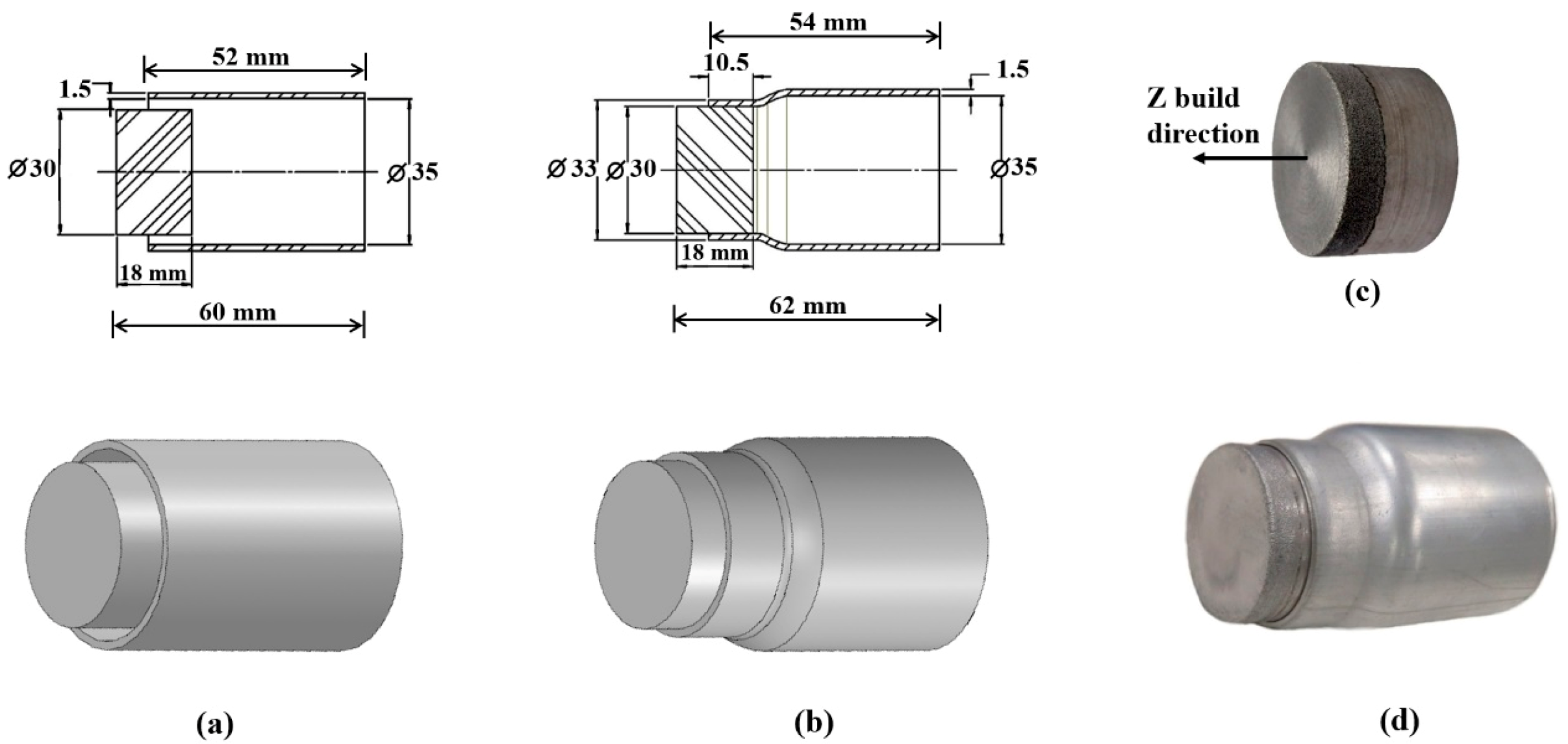
The stationary specimens, 30 mm in diameter by 18 mm in length (Figure 2a,b), were built on an L-PBF machine (EOSINT M280 machine, EOS, Krailling Germany) equipped with a 250 × 250 × 300 mm3 build-platform with an up to 400 W continuous Yb fibre laser. The parts (Figure 2) were printed from a pre-alloyed AlSi10Mg powder with a particle size in the range of 20–63 µm and a layer thickness of 30 µm, with similar particle diameters used by Inberg et al. [39]. The rods were built in the vertical (Z) direction (Figure 2c) in an argon atmosphere with maximum oxygen content of 0.12%.
The build-plate temperature was about 35 °C (recommended parameter for the EOSINT M280 printer), and the specimens underwent a post-processing T5 heat treatment at 300 °C for 2 h, with similar conditions as described by others [29,40]. The laser beam spot diameter was about 80 µm with Gaussian intensity distribution in the process plane and with an applied scanning velocity of about 1 m/s. The build-strategy was the strip (8 mm wide) scanning strategy, based on a laser scan pattern rotating by an angle of 67° between successive layers along the Z-direction. The hatch distance of about 200 µm was applied with a 33% overlap.
The components were cleaned in ethanol to remove residue from their surfaces, prior to MPW joining experiments. Preliminary tests were conducted to identify the minimum energy required for a leak-free continuous joint along the tube perimeter. The experimental runs (Figure 1a–c), with diverse charging energies, were performed on a Bmax Model 50/25 Pulse Generator (Bmax, Toulouse, France and Hod-Hasharon, Israel) with the characteristic values listed in Table 2. The current was measured for each trial with a Rogowski current probe, and the maximum current amplitude was calculated. Illustrations of samples, before and after the MPW welding process, are shown in Figure 2 and Figure 3. Specimens 1, 2, 3, 4 were produced under high-energy conditions, and specimens 5, 6, 7 were produced under optimal-energy conditions, as shown in Table 2. The optimal parameters were achieved by carrying out tests to establish collision angle, gap, positioning in coil, as well as frequency and kV.

2.2. MPW Joint Macro-Characterisation

(a)
The MPW specimens were visually tested (VT) to determine the existence of macroscopic discontinuities including jet residue on the AA6060-T6 tube inner surfaces.
(b)
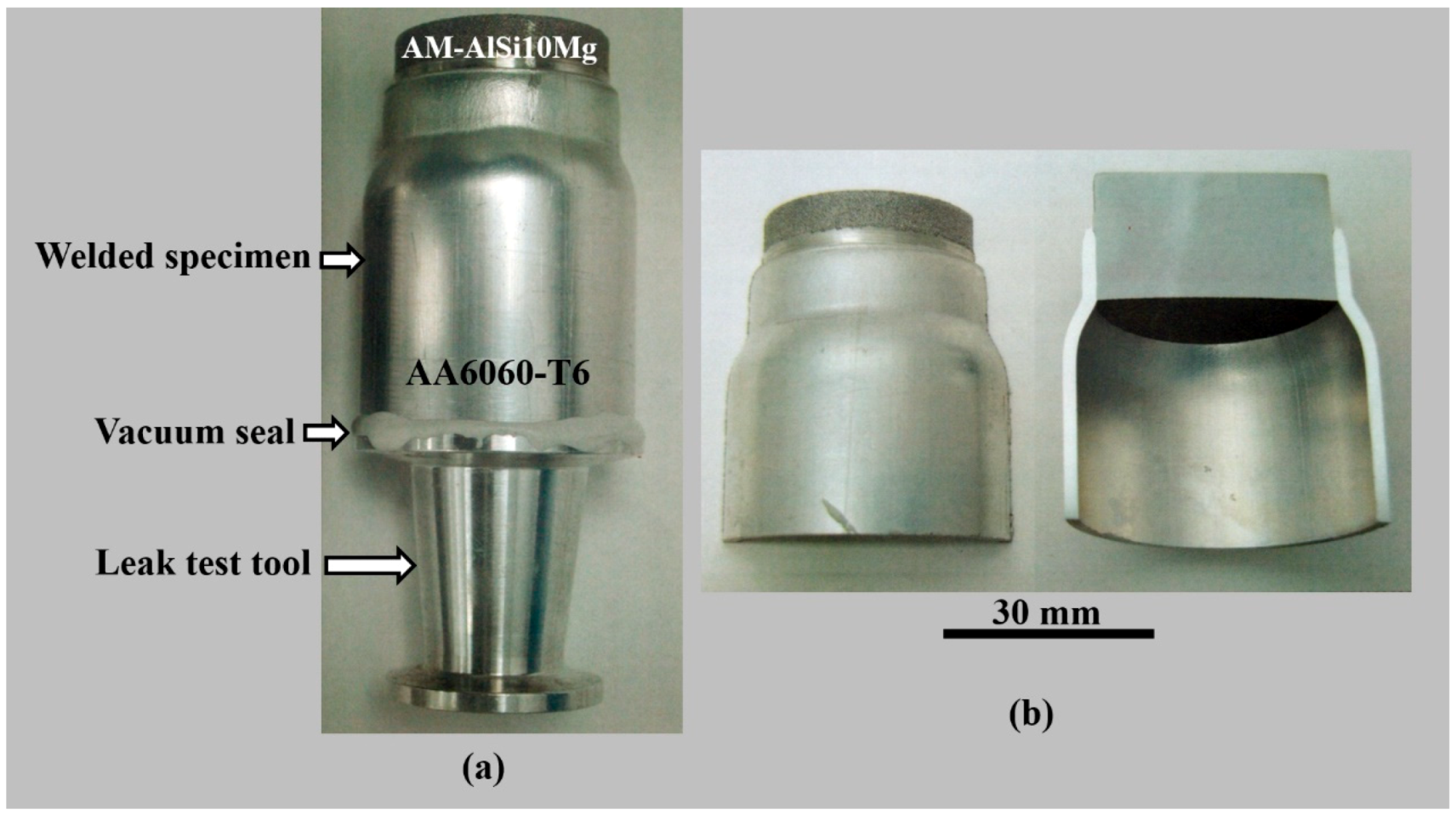
The as-welded samples were cemented to a commercial vacuum connector shown in Figure 3a. The He leak tests were performed by the “spray-probe” technique to estimate the weld quality. An EDWARDS ELD500 Helium leak detector was coupled directly to the vacuum system, to evacuate the system including the sample. The external surface of the sample was finely sprayed with Helium, particularly around the joint zone. Any tiny leak caused by defective welds, damaged gaskets, etc., will allow helium to penetrate and be detected by the leak detector, as described in DIN EN 1779:1999-10, 2011 [41] standard, and as described and performed previously by Shribman, Nahmany et al. [14].
(c)
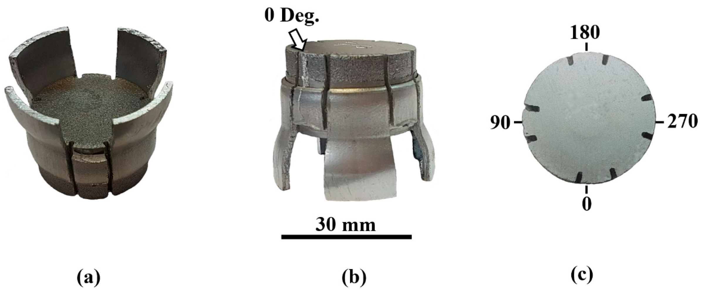
Peel tests were performed to determine the quality and failure type of joints produced by diverse welding methods, such as resistance spot welding, etc.; ISO/AWI 23,598 standard [42] specifies the geometry of test specimens and the testing procedures for such a test. A manual peel test was used to assess the macro weld quality of the welded specimens at four positions around the circumference: 0°, 90°, 180°, and 270° (Figure 4). The isometric view of the specimen after a peel test is shown in Figure 4a,b. The position at the coil’s slot (0°) is of special interest during process parameter development, due to locally reduced magnetic field intensity in this specific region.
(d)
The macroscopic deformation of the flyer tube wall, after MPW, was measured at different positions along the joint and far enough to reach the initial wall’s tube thickness.

2.3. Material Characterisation

(a)
Metallographic samples of the welded parts were prepared according to the ASTM-E3 standard. The surface preparation included sectioning, grinding, and fine polishing steps (up to 0.05 µm). The microstructure was etched with a modified Flick’s reagent (10% HF-90% H2O).
(b)
Light microscopy (LM) examination was carried out with a Zeiss, Aalen, Germany, metallographic microscope, in order to characterise the microstructure of the base materials and the joint, as well as to observe and estimate flyer tube deformation.
(c)
Vickers microhardness (HV) indentation tests were performed with a Buehler MMT-7 tester (Bühler, Uzwil, Switzerland), using a 100 g load and 10 s. duration load, in order to estimate joint mechanical properties.
(d)
Scanning electron microscopy (SEM) and energy dispersive spectroscopy (EDS) were conducted with micro FA Quanta 200FEI SEM instrument and an environmental SEM (Quanta 200FEG E-SEM, Thermo Fisher Scientific, Waltham, Massachusetts, United States) in high vacuum condition and a secondary electron detector. The SEM-EDS analysis was performed to characterise the microstructure and composition of the base materials and the joint and detect discontinuities, such as molten “pockets” and cracks.

3. Results and Discussion

3.1. Leak and Peel Tests

3.1.1. Leak Tests

Selected MP-welded samples were subjected to fine leak testing to determine the hermeticity of the joints. Typical results of He leak tests (see Section 2.2 (b) above) were as follows: 5 × 10⁻⁹ std-cc·s−1 He (specimen No. 6) and 1 × 10⁻⁹ std-cc·s−1 He (specimen No. 4). Characteristically, aerospace applications are required to have a leak rate better than 5 × 10⁻⁶ std-cc·s−1 He, in order to protect the equipment from contaminants. Both welded samples have a leak rate better than 5 × 10⁻⁹ std-cc·s−1 He, more than meeting aerospace hermeticity specifications. The leak tests demonstrate that, with a correct set of process parameters, it is feasible to produce hermetically sealed assemblies based on additively manufactured components welded to wrought parts by MPW.

3.1.2. Peel Tests

The mechanical macro-quality of the joints was assessed by manual peel test, as previously performed by others [12,13,14,43]. The outcome at the coil’s slot (0°) is of special interest due to the locally reduced magnetic field intensity in the area, leading to possible local discontinuities and low mechanical properties (Figure 4). Strips of the flyer material with a width of approximately 12 mm were axially cut and radially bent. The welded specimen was clamped, and a tension force was applied to the strips normal to the weld seam. In the case of a defective weld, the strips would separate from the stationary part. When adequate joints were obtained, the weld seam is either able to withstand the load, or the strip is expected to fail in the base material. Four peel tests were carried out on sample 1 (Figure 4), and all strips failed in the base material, with resulting strip lengths of 0°—9 mm, 90°—9 mm, 180°—10.5 mm, and 270°—9.5 mm. In MPW, the effect of the coil slot is such that magnetic pressure varies in different positions around the coil. In general, magnetic pressure, and thus, flyer velocity is highest at 180 degrees from the slot, and so the weld length is expected to be highest at the 180° position and lowest at the slot (0°). This is borne out by the above-presented results. The fact that the results of 0° and the 90° are identical, maybe due to a slight mechanical asymmetry of the parts or stray magnetism.

3.2. Flyer Tube Deformation

Typical interface morphology of welded AlSi10Mg AM L-PBF rods to AA6060-T6 wrought tubes is presented in Figure 5a–c (LM observation). The interface is relatively flat at the beginning of the joint and then becomes gradually wavy in the middle, before becoming flat near the end of the joint. This gradual change in the interface morphology was typical for all successful AM/wrought joints (Figure 5). On selected samples, the total joint length was measured and compared to the wavy zone length (Table 3). It is shown that the higher the applied energy, the greater is the joint length. Higher energy produces a higher flyer velocity. Therefore, the weld length along the interface, where the minimum flyer velocity to provide adequate welding conditions is at least maintained (as it is falling off), is increased, thus producing a longer weld.
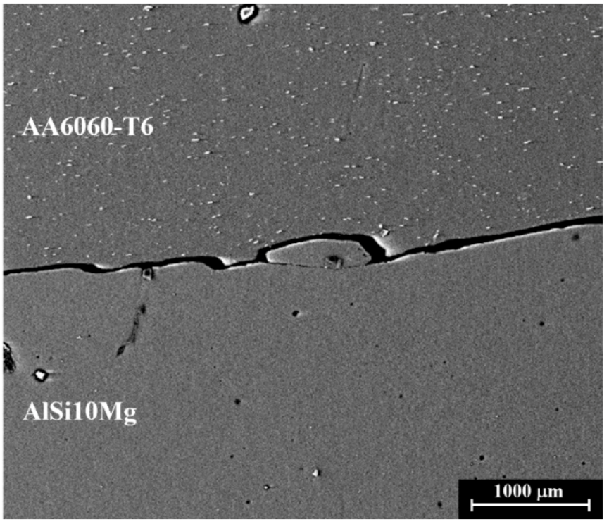
In case of MPW of specimen No. 8, where the AM-AlSi10Mg material served as flyer and AA6060-T6 alloy as stationary part, no weld was obtained. Although acceptable deformation occurred in both components and the typical flat and wavy faying interfaces were identified on both the flyer and the stationary parts, the weld failed (Figure 6, LM observation). Weak partial welding may have occurred, but the parts were probably separated by reverberating shock waves and the joint failed.
The overall radial deformation of the specimens and the tube-wall thickening at the end of MPW are exhibited in Figure 3 and Figure 5. Specimens 4 and 5 display similar performance with no visible external cracks or discontinuities in the collapsed regions of both flyers. The change in the flyer’s wall thickness, measured in the welding direction (specimen No. 5), was assessed from the initial impact zone, along the weld zone and the inclined tube’s region, up to the undeformed original tube. An example of the thickness evolution of the flyer wall is presented in Figure 5a,b. The initial wall thickness of 1.5 mm slightly decreases adjacent to the free flyer edge and then gradually increases, reaching ~1.8 mm in most of the weld zone (Figure 5b). Under the reasonable assumption that almost no material was lost (during jetting), the experimental values agree well with the calculated and expected thickening of the tube’s wall, when taking into account that the major compression/deformation has occurred in the fully collapsed region of ~10.5 mm. The thickening effect of the flyer’s wall is clearly displayed in Figure 5, from an initial wall thickness of 1.5 mm, through 1.65 mm and 1.75 mm, reaching a maximum value of 1.8 mm in most of the weld zone. A summary of the walls’ average thicknesses, measured at two or four locations, is shown in Table 3. The average indentation depth of the flyer into the stationary part was ~0.3 mm (Figure 5a,b). Comparing the indentation data and bearing in mind that different applied energy values were used in the welding experiments, no major differences were identified. This is a positive finding, demonstrating the low sensitivity of the joint quality to the welding parameters. Furthermore, the geometrical design chosen for the parts was found stable and can be well-considered for scaling-up and even industrialisation of the MPW process for joining the current AM alloys to wrought alloys. The indentation depth of the flyer into the stationary part is very much determined by the mechanical properties of the stationary component material. The minor indentation of the flyer into the AM L-PBF material, having relatively high mechanical properties when compared to the wrought material, is an advantage in favour of the hybrid assemblies. The thickening effect of the flyer’s wall, accompanied by a minor indentation in the stationary part, lowers the overall dimensional changes of the as-welded assembly.

3.3. Microhardness Across the Interface

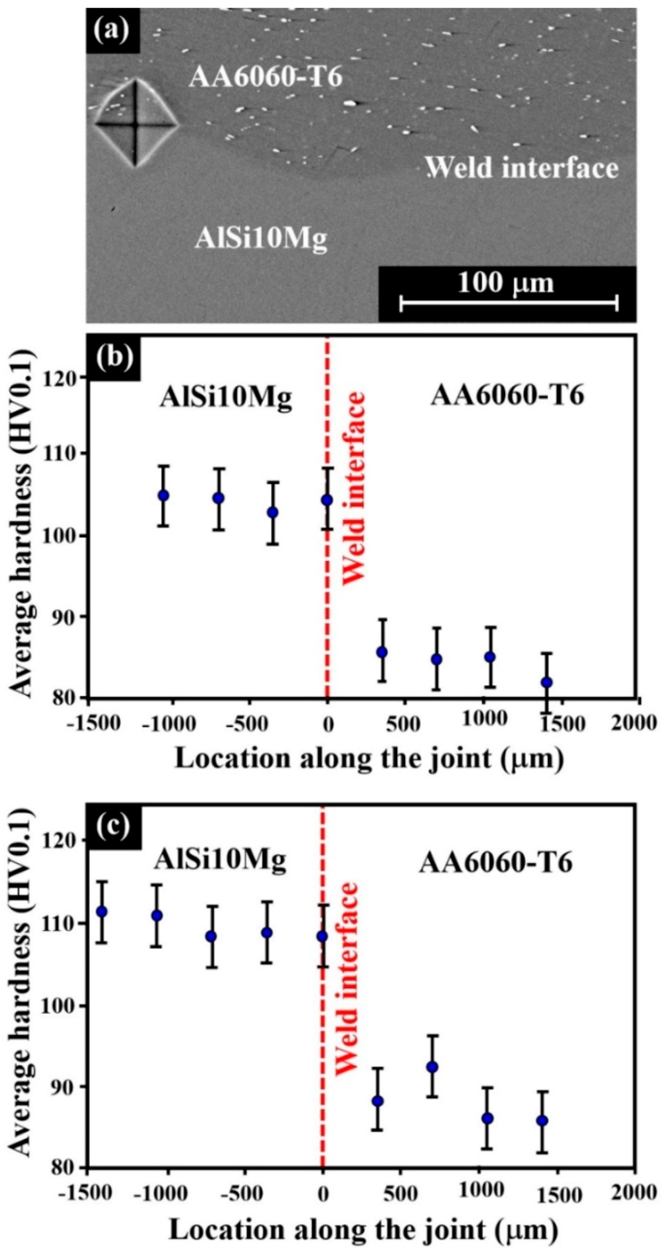
In order to evaluate the local changes adjacent to the interface, LM and SEM analyses were supported by Vickers microhardness tests (Figure 7a, SEM observation). The microhardness measurements were conducted in several locations along the joint and were performed perpendicularly to the weld line, crossing the interface from AlSi10Mg-BM to AA6060-T6 BM. Typical results are presented in Figure 7, where location “0” represents the joint interface and negative locations are situated in the AM-AlSi10Mg material. Only a slight change in microhardness was detected adjacent to the joint interface, with a smaller increase observed in the AA6060-T6 material (Figure 7b,c). The small increase in microhardness can be attributed to the deformation and local heating of the alloys during the impact welding.

3.4. Microanalysis of the Joint

3.4.1. Interfacial Layers or “Pockets”

All faying interfaces show a metal continuity that can either be flat or wavy; the interface is initially relatively flat, and waves form and grow in the welding direction. According to Zhang [43], the wavy morphology of the weld rises in the intimate contact zone and helps interlocking between the two surfaces, creating much more robust joints. Ben-Artzy et al. [16] described that the wavy interface of the weld is typically formed in a periodic manner with defined wavelength and amplitude. Sridharan et al. [17] studied the joint in Al and Fe welds using a vaporising foil actuator welding (VFAW) system. They presented a pronounced hierarchical nature at the interface. A wavy interface was found, as the result of high plastic deformation. A SEM study indicated the development of a liquid layer at the interface, also as mentioned in previous studies [7,14,22] and in ISO/AWI 23,598 (2019) [42]. Most researchers believe that the interfacial waviness is produced by the Kelvin–Helmholtz instability mechanism, i.e., the reflected shock waves interact with the collision point at the interface, where interferences are the source for wave initiation. Collision energy and joint geometry are believed to have the most significant influence on the interfacial wave morphology; high energy use results in long wavelength and high wave amplitude.
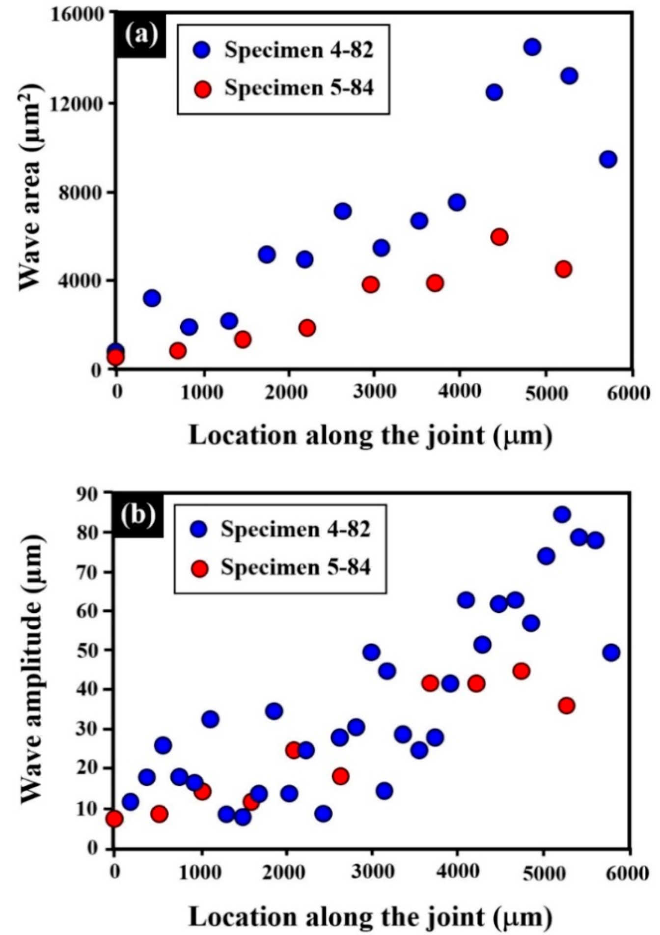
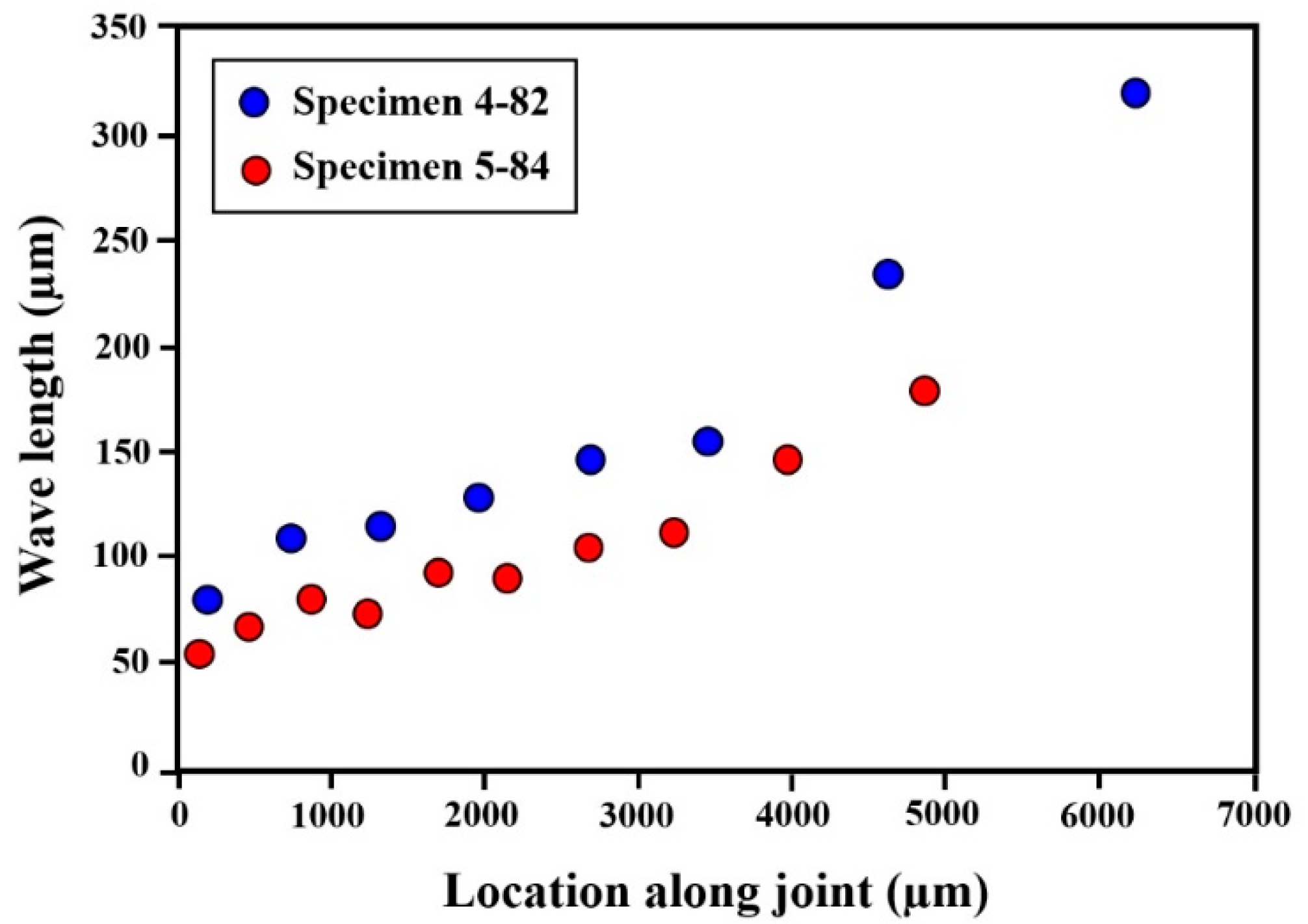
Figure 8a,b illustrate the evolution of the wave area and amplitude as a function of weld length for the two applied energies. High-energy welds present larger waves than the optimal-energy welds (Figure 8 and Figure 9). In Figure 9, the wavelength is plotted against the weld length; the figure shows that the wavelength increases with increasing weld energy. The optimal-energy welds present more waves, i.e., a shorter wavelength. The results are in accord with the previous experimental observations, as reported by Ben-Artzy et al. [16].
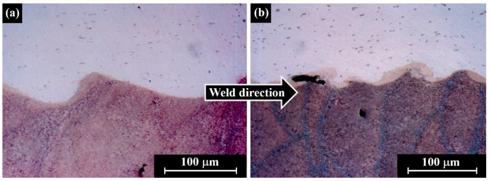
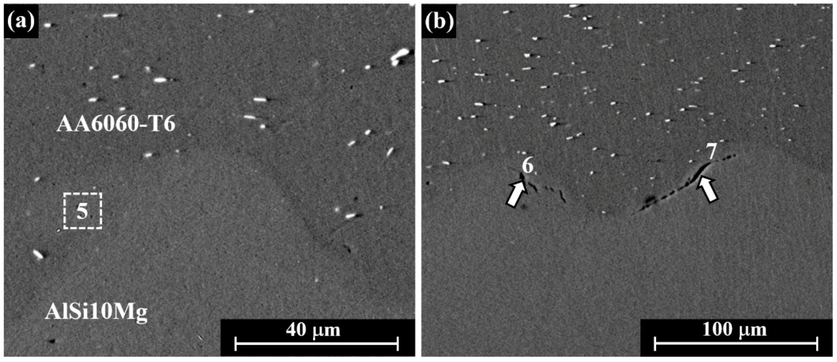
Along the wavy joints, “pockets” or occasional discontinuous short layers, exhibiting different morphologies, were detected and analysed. Typically, the optimal-energy weld presents fewer “pockets” than high-energy welds, as demonstrated in Figure 10a,b. A comparison was made between high-energy welds, (specimen No. 4) and “optimal-energy” welds (specimen No. 6) and the results are reflected in Figure 11 and Figure 12. No detectable heat-affected zone was observed adjacent to the faying interfaces of both high-energy welds and optimal-energy welds. Cracks and/or pores were occasionally found (Figure 10b and Figure 12b, LM and SEM observation, respectively) in the “pockets” of high-energy welds, while the optimal-energy welds (specimen No. 6) presented no crack comparable “pockets”. This phenomenon was also reported previously, probably when employing suboptimal welding parameters, by the same method described in Shribman et al. [14].
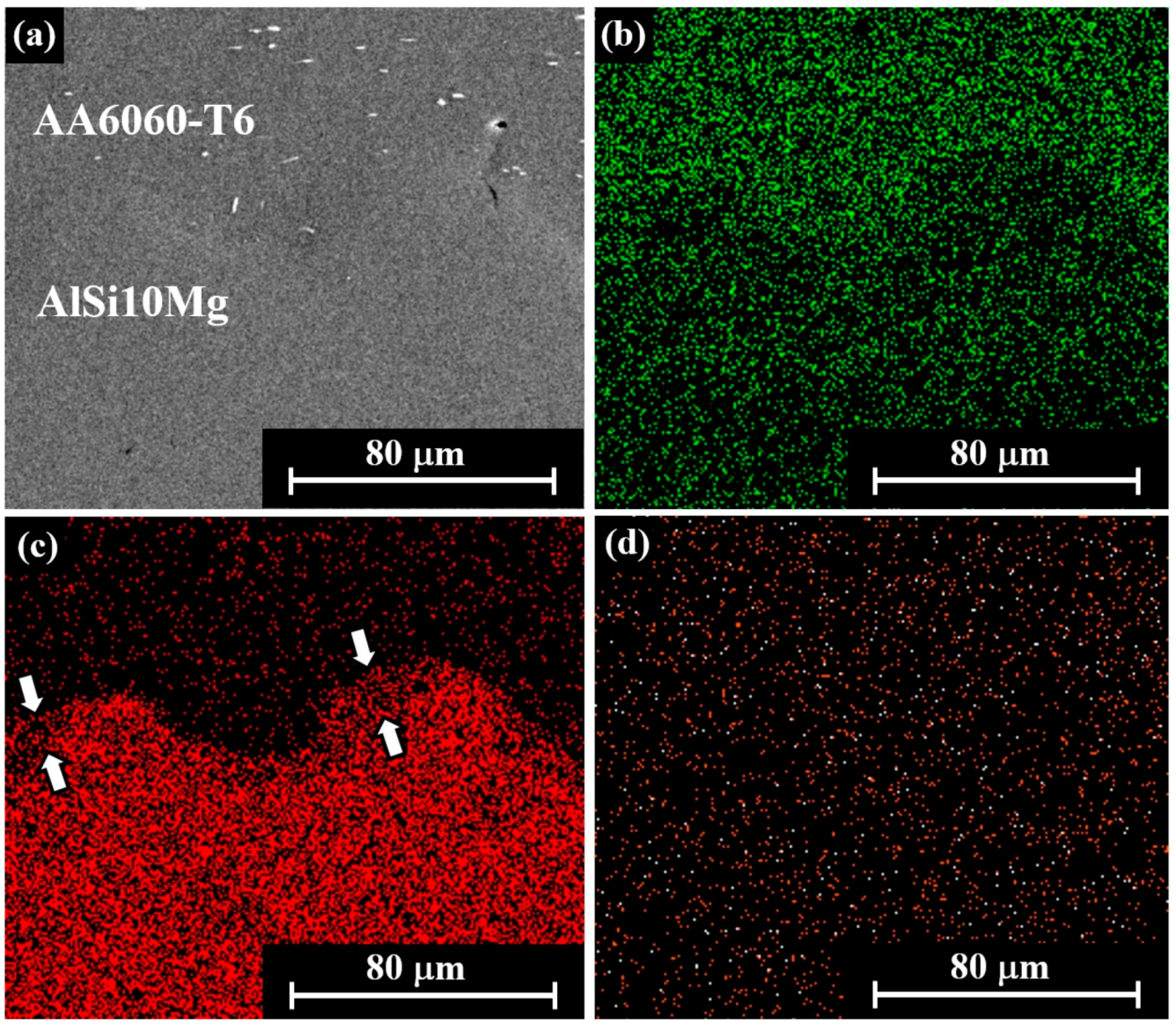
Element maps were acquired from the polished cross-sections adjacent to the interface (Figure 11a, SEM) showing the spatial distribution of Al, Si, and Mg (Figure 11b–d, EDS analysis). The element maps were found to be beneficial for displaying element distributions and compositional zonation in the regions where “pockets” or discontinuous short layers were detected. Si “depletion” is evident (marked with arrows in Figure 11), when compared to the AM-AlSi10Mg BM composition, proving that local melting has occurred during the welding process.

3.4.2. EDS of Interfacial Layers or “Pockets”

EDS microanalysis across the peak and valley of the waves, within “pockets” (specimen No. 6) and/or intermediate layers (specimen No. 4) was performed to determine (Figure 12) the local chemical composition of selected regions; the results are shown in Table 4. In both specimens, the Si content (point 5 in Figure 12a and points 6 and 7 in Figure 12b) is roughly half the Si content in the AM-AlSi10Mg BM. At these locations, layers from both base metals melt and mix, and the resolidified zones present an average Si concentration of 5.2 wt%, roughly averaging the Si content (~0.5 wt% and ~10 wt%) of the base metals. These findings may lead to the conclusion that the “pockets” consist of a resolidified molten mix of base metals in roughly equal quantities of both alloys, as suggested previously [14]. Some cracking has been occasionally noticed along the wavy joint, with an example illustrated in Figure 12b. Local cracking was reported in the literature, but on a much larger scale, probably related to the inherent properties of the welded alloys and the applied welding parameters (ISO/AWI 23598, 2019).

3.5. Jet Characterisation

In previous works done by Stern et al. [9] and Shribman et al. [14], jet residues located towards the end of the weld zone were observed and examined. The agglomeration of the ejected remains from the interface near the end zone of the weld confirm a temperature rise that exceeds the melting temperature of the alloys. In the current study, a few local accumulations of Si particles (93.7 wt%) were also detected between the jet residues. The SEM-EDS microanalyses of the debris indicate that the elemental composition values are intermediate between the compositions of the two base metals; the jet contains approximately 7.5 wt% Si and some traces of Mg. Further investigations of jet residue located near the end of the weld zone and on the inner flyer surfaces were conducted. Residue in the form of faded black areas and lines was clearly observed, visually, on the interior flyer surface (Figure 4b and Figure 13). Those faded findings were ejected during the welding process and deposited on the tube interior surface as the black films (Figure 4b and Figure 13). The most noticeable black area is located adjacent to the coil slot (coil origin), as a result of higher material ejection from this specific location, possibly due to decreased energy facing the slot and, thus, reduced impact and collision point velocity, enabling more time for jet production (see arrows in Figure 13a and enlarged in Figure 13b). The EDS-SEM analysis could not identify any differences in the chemical composition, probably because of the jet film being extremely thin.
In the present study, some jet residue in the form of a very thin metal film (less than 0.1µm) was discovered in between the welded parts (Figure 14a–d, SEM observation); the element distribution in selected regions is displayed in Table 5. This type of thin metal film jet, discovered for the first time in this work, is probably connected to the fluid metal jetting phenomena. During the MPW process, high impact energies are concentrated in a small material volume and generate a considerable local increase in temperature, leading to melting or even vaporisation of thin superficial layers from both colliding parts. The solidification of liquefied/vaporised jet material probably formed this type of thin metal foil. The thin film phenomenon might be attributed to the weld process with the AM-AlSi10Mg alloy, which has a lower melting point compared to the wrought AA6060 alloy (~577 °C, ~650 °C respectively). Nevertheless, the phenomenon was only detected when high-energy welding conditions were utilised and was not reported earlier, when welding “conventional” alloys. Fluid metal jetting, leaving behind elevated melting temperature particles, is also the reason for the formation of tiny Si agglomerates within the bonding zone, as shown in Figure 14d and Table 5. It is worth noting that jet residue, in the form of thin films, was only observed in the samples welded using high-energy parameters. Figure 15 shows an AM local breakage that occurred after the weld, away from the end of the weld. It is noteworthy that these phenomena are different from the observation in the previous work done by Shribman et al. [14], probably due to the optimal-energy weld specimen No. 6, in contrast to high-energy weld specimen No. 4 at this point. The compositions of jet residue were investigated by SEM-EDS spot analyses, and the results are listed in Table 5. The jet fragments contain alloying elements found in both components (Si, Mg), including small amounts of S, Fe, and Cu. Copper’s source found in some locations is uncertain. The copper contamination may come from Cu-containing parts of the MPW apparatus, such as the coil. Areas 36–38 (white dash rectangular) were examined by EDS (Table 5).

4. Conclusions

L-PBF of metals is an AM expanding technology that, up to this point, is hindered by the significant limitations of the printed component size. This novel contribution addresses PBF machine size limitations by developing a high-quality joining method between L-PBF and conventionally fabricated materials. The current study is part of continuing research dealing with joining of AM to wrought material and/or AM to AM. This novel contribution is mainly focused on the analyses of both optimal- and high-energy welding conditions.
The current study demonstrates that it is possible to hermetically join L-PBF additive manufactured components to wrought parts by the MPW technique when using an adjusted set of process parameters. The use of L-PBF AlSi10Mg eutectic material—having a lower melting temperature than the wrought material, while exhibiting relatively high mechanical properties—enables the formation of high-quality welds at lower MPW energies. Thus, the loading on the MPW tool coils provides substantially reduced lifetime effects.
The macro and microstructural evolution of the joint shows an increase in amplitude, area, and wavelength of the wavy interfaces, for both optimal- and high-energy joints, as the weld propagates. The joint formation is accompanied by flyer wall thickening, the result of the significant diametral inward deformation of the tube occurring during the welding process. The wall thickening and the wavy interface development are believed to be physical indicators of process parameters optimisation, as they contribute to the mechanical properties of the joint.
Microhardness indentation tests performed perpendicularly to the weld line, crossing the interface between AlSi10Mg rod and AA6060-T6 wrought tube, revealed that the microhardness has increased slightly, adjacent to the interface. This phenomenon is probably due to high-velocity impact occurring in MPW, causing major deformation of the flyer tube, and in the current case, minor deformation of the stationary part.
Due to the excessive kinetic energy derived from the impact, localised interfacial melting occurs; resolidified regions in the form of singular “pockets” have been observed. In the high-energy MP welds, discontinuous resolidified layers have been also detected. The EDS-SEM microanalysis results suggest that superficial layers from both base metal’s melt and mix during welding, forming the resolidified regions. Jet residue showing irregular morphologies was detected, occasionally in form of small conglomerates containing Si particles (93.7 wt%) and as very thin films (less than 100 nm thick) located in between the components. High-energy MPW, leading to a significant temperature increase, may cause the emission of the vaporised jets creating discrete Si particles and thin films. It is worth noting that this type of jet residue was discovered for the first time in the current research.
The study shows that magnetic pulse welding provides metallurgical joints with a very small environmental footprint, offering high-quality bonding of dissimilar AlSi10Mg AM L-PBF rod and AA6060-T6 wrought tube, while exhibiting a negligible heat-affected zone. The study provides additional information concerning weld formation mechanisms of additively manufactured parts to conventional wrought parts by MPW, which conform to existing weld knowledge. Although the AM-to-wrought MP-weld mechanism looks similar to the known MPW mechanism, it is a note-worthy outcome that AM alloys can be readily MP-welded. The “thin film” phenomenon needs to be explored further.

Author Contributions

Conceptualization, M.N., V.S. and A.S.; methodology, M.N., V.S. and A.S.; validation, M.N., V.S., D.A. and A.S.; formal analysis, M.N., V.S., D.A. and A.S.; investigation, M.N. and S.L.; resources, M.N., V.S., D.A. and A.S.; data curation, M.N., V.S.; writing—original draft preparation, M.N., V.S., D.A. and A.S.; writing—review and editing, M.N., V.S., D.A. and A.S.; visualization, M.N. and D.A.; supervision, A.S.; project administration, D.A.; All authors have read and agreed to the published version of the manuscript.

Funding

This research received no external funding.

Acknowledgments

The authors are grateful to thank Y. Sharon of “Sharon Tuvia (1982)” Ltd., Ness Tziona, Israel, for supplying the AM L-PBF samples. The authors would also like to thank I. Benishti of NRCN, E. Millionshckik of the Ben-Gurion University of the Negev, O. Atiya formerly of Bmax Srl. and Z. Barkay of the Wolfson Applied Materials Research Centre, Tel Aviv University, for their valuable technical contributions.

Conflicts of Interest

The authors declare no conflict of interest.

References

  1. Bataev, I.A.; Ivanov, I.V.; Malyutina, Y.N.; Emurlaev, K.I.; Emurlaeva, Y.Y. High plastic deformations and high cooling rates at the interface of explosion-welded materials. Met. Sci. Heat Treat. 2019, 60, 674–679. [Google Scholar] [CrossRef]
  2. Lee, T.; Zhang, S.; Vivek, A.; Daehn, G.; Kinsey, B. Wave formation in impact welding: Study of the Cu–Ti system. CIRP Ann. 2019, 68, 261–264. [Google Scholar] [CrossRef]
  3. Nassiri, A.; Abke, T.; Daehn, G. Investigation of melting phenomena in solid-state welding processes. Scr. Mater. 2019, 168, 61–66. [Google Scholar] [CrossRef]
  4. Carlone, P.; Astarita, A. Dissimilar metal welding. Metals 2019, 9, 1206. [Google Scholar] [CrossRef] [Green Version]
  5. Raoelison, R.N.; Sapanathan, T.; Buiron, N.M.; Rachik, M. Magnetic pulse welding of Al/Al and Al/Cu metal pairs: Consequences of the dissimilar combination on the interfacial behaviour during the welding process. J. Manuf. Process. 2015, 20, 112–127. [Google Scholar] [CrossRef]
  6. Stern, A.; Aizenshtein, M. Bonding zone formation in magnetic pulse welds. Sci. Tech. Weld. Join. 2002, 7, 339–342. [Google Scholar] [CrossRef]
  7. Stern, A.; Shribman, V.; Ben-Artzy, A.; Aizenshtein, M. Interface phenomena and bonding mechanism in magnetic pulse welding. J. Mater. Eng. Perform. 2014, 23, 3449–3458. [Google Scholar] [CrossRef]
  8. Kakizaki, S.; Watanabe, M.; Kumai, S. Simulation and experimental analysis of metal jet emission and weld interface morphology in impact welding. Mater. Trans. 2011, 152, 1104181357. [Google Scholar] [CrossRef] [Green Version]
  9. Stern, A.; Becher, O.; Nahmany, M.; Ashkenazi, D.; Shribman, V. Jet composition in magnetic pulse welding: Al–Al and Al-Mg couples. Weld. J. 2015, 94, 258s–264s. [Google Scholar]
  10. Wang, X.; Zheng, Y.; Liu, H.; Shen, Z.; Hu, Y.; Li, W.; Gao, Y.; Guo, C. Numerical study of the mechanism of explosive/impact welding using smoothed particle hydrodynamics method. Mater. Des. 2012, 35, 210–219. [Google Scholar] [CrossRef]
  11. Bellmann, J.; Beyer, E.; Lueg-Althoff, J.; Gies, S.; Tekkaya, A.E.; Schulze, S. Measurement of collision conditions in magnetic pulse welding processes. J. Phys. Sci. Appl. 2017, 7, 1–10. [Google Scholar] [CrossRef] [Green Version]
  12. Lueg-Althoff, J.; Bellmann, J.; Gies, S.; Schulze, S.; Tekkaya, A.E.; Beyer, E. Influence of the flyer kinetics on magnetic pulse welding of tubes. J. Mater. Process. Tech. 2018, 262, 189–203. [Google Scholar] [CrossRef]
  13. Pourabbas, M.; Abdollah-Zadeh, A.; Sarvari, M.; Pouranvari, M.; Miresmaeili, R. Investigation of structural and mechanical properties of magnetic pulse welded dissimilar aluminum alloys. J. Manuf. Processes 2019, 37, 292–304. [Google Scholar] [CrossRef]
  14. Shribman, V.; Nahmany, M.; Levi, S.; Atiya, O.; Ashkenazi, D.; Stern, A. MP welding of dissimilar materials: AM laser powder-bed fusion AlSi10Mg to wrought AA6060-T6. Prog. Addit. Manuf. 2019, 5, 71–181. [Google Scholar] [CrossRef]
  15. Debroy, T.; Wei, H.L.; Zuback, J.S.; Mukherjee, T.; Elmer, J.W.; Milewski, J.O.; Beese, A.M.; Wilson-Heid, A.; De, A.; Zhang, W. Additive manufacturing of metallic components—Process, structure, and properties. Prog. Mater. Sci. 2018, 92, 112–224. [Google Scholar] [CrossRef]
  16. Ben-Artzy, A.; Stern, A.; Frage, N.; Shribman, V.; Sadot, O. Wave formation mechanism in magnetic pulse welding. Int. J. Impact Eng. 2010, 37, 397–404. [Google Scholar] [CrossRef]
  17. Sridharan, N.; Poplawsky, J.; Vivek, A.; Bhattacharya, A.; Guo, W.; Meyer, H.; Mao, Y.; Lee, T.; Daehn, G. Cascading microstructures in aluminum-steel interfaces created by impact welding. Mater. Character. 2019, 151, 119–128. [Google Scholar] [CrossRef]
  18. Bellmann, J.; Lueg-Althoff, J.; Schulze, S.; Hahn, M.; Gies, S.; Beyer, E.; Tekkaya, A.E. Thermal effects in dissimilar magnetic pulse welding. Metals 2019, 9, 348. [Google Scholar] [CrossRef] [Green Version]
  19. Böhme, M.; Sharafiev, S.; Schumacher, E.; Böhm, S.; Wagner, M.F.X. On the microstructure and the origin of intermetallic phase seams in magnetic pulse welding of aluminum and steel. Mater. Werkst. 2019, 50, 958–964. [Google Scholar] [CrossRef]
  20. Geng, H.; Mao, J.; Zhang, X.; Li, G.; Cui, J. Formation mechanism of transition zone and amorphous structure in magnetic pulse welded Al-Fe joint. Mater. Lett. 2019, 245, 151–154. [Google Scholar] [CrossRef]
  21. Sapanathan, T.; Yang, K.; Chernikov, D.; Raoelison, R.N.; Gluschenkov, V.; Buiron, N.; Rachik, M. Thermal effect during electromagnetic pulse welding process. In Materials Science Forum; Trans Tech Publications: Stafa-Zurich, Switzerland, 2017; Volume 879, pp. 1662–1667. [Google Scholar]
  22. Sharafiev, S.; Pabst, C.; Wagner, M.F.; Groche, P. Microstructural characterization of interfaces in magnetic pulse welded aluminum/aluminum joints. In Proceedings of the IOP Conference Series: Materials Science and Engineering, Rourkela, Bangalore, India, 14–16 July 2016; IOP Publishing: Bristol, UK, 2016; Volume 118, p. 012016. [Google Scholar]
  23. Aboulkhair, N.T.; Simonelli, M.; Parry, L.; Ashcroft, I.; Tuck, C.; Hague, R. 3D printing of aluminium alloys: Additive manufacturing of aluminium alloys using selective laser melting. Prog. Mater. Sci. 2019, 106, 100578. [Google Scholar] [CrossRef]
  24. Zhang, D.; Sun, S.; Qiu, D.; Gibson, M.A.; Dargusch, M.S.; Brandt, M.; Qian, M.; Easton, M. Metal alloys for fusion based additive manufacturing. Adv. Eng. Mater. 2018, 20, 1700952. [Google Scholar] [CrossRef]
  25. Zuback, J.S.; DebRoy, T. The hardness of additively manufactured alloys. Materials 2018, 11, 2070. [Google Scholar] [CrossRef] [PubMed] [Green Version]
  26. Mertens, A.I.; Delahaye, J.; Lecomte-Beckers, J. Fusion-based additive manufacturing for processing aluminum alloys: State-of the-art and challenges. Adv. Eng. Mater. 2017, 19, 1700003. [Google Scholar] [CrossRef]
  27. Rosenthal, I.; Stern, A.; Frage, N. Strain rate sensitivity and fracture mechanism of AlSi10Mg parts produced by selective laser melting. Mater. Sci. Eng. A 2017, 682, 509–517. [Google Scholar] [CrossRef]
  28. Awd, M.; Siddique, S.; Johannsen, J.; Emmelmann, C.; Walther, F. Very high-cycle fatigue properties and microstructural damage mechanisms of selective laser melted AlSi10Mg alloy. Int. J. Fatigue 2019, 124, 55–69. [Google Scholar] [CrossRef]
  29. Rosenthal, I.; Shneck, R.; Stern, A. Heat treatment effect on the mechanical properties and fracture mechanism in AlSi10Mg fabricated by additive manufacturing selective laser melting process. Mater. Sci. Eng. A 2018, 729, 310–322. [Google Scholar] [CrossRef]
  30. Tradowsky, U.; White, J.; Ward, R.M.; Read, N.; Reimers, W.; Attallah, M.M. Selective laser melting of AlSi10Mg: Influence of post-processing on the microstructural and tensile properties development. Mater. Des. 2016, 105, 212–222. [Google Scholar] [CrossRef] [Green Version]
  31. Biffi, C.A.; Fiocchi, J.; Tuissi, A. Laser weldability of AlSi10Mg alloy produced by selective laser melting: Microstructure and mechanical behavior. J. Mater. Eng. Perform. 2019, 28, 1–6. [Google Scholar] [CrossRef]
  32. Nahmany, M.; Hadad, Y.; Aghion, E.; Stern, A.; Frage, N. Microstructural assessment and mechanical properties of electron beam welding of AlSi10Mg specimens fabricated by selective laser melting. J. Mater. Process. Tech. 2019, 270, 228–240. [Google Scholar] [CrossRef]
  33. Zhang, C.; Bao, Y.; Zhu, H.; Nie, X.; Zhang, W.; Zhang, S.; Zeng, X. A comparison between laser and TIG welding of selective laser melted AlSi10Mg. Optic. Laser Tech. 2019, 120, 105696. [Google Scholar] [CrossRef]
  34. Nahmany, M.; Stern, A.; Benishti, I.; Rosenthal, I.; Frage, N. Electron beam welding of AlSil0Mg workpieces produced by selected laser melting additive manufacturing technology. Addit. Manuf. 2015, 8, 63–70. [Google Scholar]
  35. Nahmany, M.; Stern, A.; Aghion, E.; Frage, N. Structural properties of EB-welded AlSi10Mg thin-walled pressure vessels produced by AM-SLM technology. J. Mater. Eng. Perform. 2017, 26, 4813–4821. [Google Scholar] [CrossRef]
  36. Tavlovich, B.; Shirizly, A.; Katz, R. EBW and LBW of additive manufactured Ti6Al4V products. Weld. J. 2018, 97, 179S–190S. [Google Scholar]
  37. Wits, W.W.; Becker, J.J. Laser beam welding of titanium additive manufactured parts. Procedia CIRP 2015, 28, 70–75. [Google Scholar] [CrossRef] [Green Version]
  38. Adamczyk-Cieślak, B.; Mizera, J.; Kurzydłowski, K.J. Microstructures in the 6060 aluminium alloy after various severe plastic deformation treatments. Mater. Character. 2011, 62, 327–332. [Google Scholar] [CrossRef]
  39. Inberg, A.; Ashkenazi, D.; Kimmel, G.; Shacham-Diamand, Y.; Stern, A. Gold–silver electroless plating on laser powder-bed fusion additively printed AlSi10Mg parts. Metals 2020, 10, 557. [Google Scholar] [CrossRef]
  40. Inberg, A.; Ashkenazi, D.; Kimmel, G.; Shacham-Diamand, Y.; Stern, A. Gold plating of AlSi10Mg parts produced by a laser powder-bed fusion additive manufacturing technique. Prog. Addit. Manuf. 2020, 1–10. [Google Scholar] [CrossRef]
  41. DIN EN. 1779:1999-1. Non-destructive testing Leak testing-Criteria for the method and technique selection. In Din 1779, New European Standard for the Selection of A Suitable Method for Leak Detection and Leak Tightness Testing; Beuth: Berlin, Germany, 2011. [Google Scholar]
  42. ISO/AWI 23598 (under development). Mechanical Joining—Destructive Testing of Joints—Specimen Dimensions and Test Procedure for Mechanized Peel Testing of Single Joints; ISO: Geneva, Switzerland, 2019. [Google Scholar]
  43. Zhang, Y. Investigation of Magnetic Pulse Welding on Lap Joint of Similar and Dissimilar Materials. Ph.D. Thesis, The Ohio State University, Columbus, OH, USA, 2010. [Google Scholar]
Figure 1. The experimental magnetic pulse welding (MPW) system: (a) schematic illustration of a tubular configuration of the MPW setup; (b) the coil setup (centre of image); (c) the cylindrical non-conductive green part centres the two parts (side view).
Metals 10 01235 g001
Figure 2. The flyer and stationary components and the integrated AM L-PBF-AlSi10Mg and wrought AA6060-T6 parts: (a) Computer-aided design (CAD) model of the two parts (flyer and stationary components) prior to the MPW welding process; (b) CAD model of the welded specimen simulation; (c) the L-PBF-AlSi10Mg stationary component after surface machining, build-direction included; (d) the AlSi10Mg and wrought AA6060-T6 assembly after MPW.
Metals 10 01235 g002
Figure 3. General view of MP-welded specimen No. 6 used for leak test: (a) L-PBF AlSi10Mg rod is seen on the upper side and AA6060-T6 tube in the middle; the leak test adaptor appears on the lower side; (b) the AA6060-T6 tube is “wrapping” the L-PBF printed rod. The fully collapsed region length for all the samples is about 10.5 mm.
Metals 10 01235 g003
Figure 4. The AlSi10Mg and AA6060-T6 MPW-welded specimen (sample No. 1): (a) and (b) isometric view of the specimen after peel test; (c) top view of the welded specimen.
Metals 10 01235 g004
Figure 5. Joint cross-section: (a) radial deformation behaviour of the flyer: thickening effect of the flyer tube; indentation depth of the flyer into the stationary part is ~0.3 mm; (b) local wall thickness; practically similar results for specimens 4, 5, 6; (c) general view of specimen No. 6 interface morphology; the weld includes a wavy region and two flat areas, before and after the wavy zone.
Metals 10 01235 g005
Figure 6. Wavy surfaces appearance of No. 8 MPW specimen, which underwent normal deformation, but no weld was obtained: (a) L-PBF flyer tube; (b) wrought material stationary part. The waves are smaller at the beginning, increasing in weld direction.
Metals 10 01235 g006
Figure 7. Vickers microhardness across the weld interface: (a) SEM image of the indentation mark at the interface; (b) high energy (specimen No. 4); (c) optimal energy (specimen No. 5); “0” location marks the joint interface.
Metals 10 01235 g007
Figure 8. Evolution of wave area and amplitude: (a) Wave area distribution of high-energy (specimen No. 4) and optimal-energy (specimen No. 5) welds along the joint. Wave area was measured as the area under the wave; (b) wave amplitude distribution for high-energy (specimen No. 4) and optimal-energy (specimen No. 5) welds along the joint. Wave amplitude was measured peak-to-peak (error ± 5 µm). “0” indicates the beginning of the wavy region.
Metals 10 01235 g008
Figure 9. Development of wavelength in the weld direction for optimal- and high-energy joints (error ± 5 µm).
Metals 10 01235 g009
Figure 10. Wavy interface SEM micrographs: (a) An optimal-energy weld (specimen No. 5); (b) a high-energy weld (specimen No. 4). L-PBF build-orientation is opposite to the weld direction. The white arrows show the melted pockets.
Metals 10 01235 g010
Figure 11. SEM–energy dispersive spectroscopy (EDS) element mapping at the MPW interface: (a) general SEM view, (b) Al, (c) Si, and (d) Mg. molten “pockets” are visible in Figure 11c and marked by arrows.
Metals 10 01235 g011
Figure 12. SEM micrographs of selected “pockets” found adjacent to the wavy interface (high-energy weld specimen No. 4): (a) area 5, and (b) points 6, 7 designate the locations of EDS microanalysis. The white arrows in Figure 12b indicate local interface cracking.
Metals 10 01235 g012
Figure 13. Jet residue found on the inner surface of the flyer tube: (a) General view; (b) zooming at jet residue origin. The arrows refer to the parallel location of the coil origin, showing a local discontinuity and a significant jetting source.
Metals 10 01235 g013
Figure 14. SEM micrographs of typical jet thin films found close to the end of the weld (specimen No. 4), showing the locations examined by EDS (Table 5): (a) points 27–31; (b) points 41–43; (c) point 33; (d) points 34, 35.
Metals 10 01235 g014
Figure 15. Local breakage adjacent to unwelded interface, aside from the joint region.
Metals 10 01235 g015
Table 1. The chemical composition of the stationary part (additive manufactured (AM) laser powder-bed fusion (L-PBF)-AlSi10Mg) and the flyer (wrought AA6060-T6) component (wt%).
AlloyComposition (wt%)
AlSiMgFeCuMnZnVTiNi
AM L-PBF AlSi10MgBal.9.630.320.140.01≤0.010.01≤0.01
Wrought AA6060-T6Bal.0.510.400.210.030.050.020.020.020.01
Table 2. MPW system parameters for the high and optimal welding energy samples, AM L-PBF AlSi10Mg stationary and AA6060-T6 flyer pairs: gap 2.5 mm (specimen No. 1—gap 1.5 mm).
Specimen Type and No.Energy (kJ)Voltage (kV)Current-Imax (kA)
High energy: 1, 2, 3, 49.711478
Optimal energy: 5, 6, 78.010421
Table 3. Total MPW average joint lengths, including the planar and wavy regions.
Measured DistanceSpecimen No.
4 (High Energy)5 (Optimal Energy)
Joint length (µm)80295789
Wavy length (µm)60494945
Collapsed flyer thicknesses of welds (µm)17751827
Table 4. SEM-EDS microanalysis (wt%) of typical “pockets” found adjacent to the wavy interface of MP welds (see points 5, 6, 7 in Figure 12).
ElementMeasurement Locations, (wt%)
567AA6060-BMAM-BM
Mg0.10.10.10.20.2
Al94.294.295.299.889.3
Si5.75.74.710.6
Table 5. Chemical composition by SEM-EDS (wt%) in several locations of specimen No. 4; composition of both base metals is shown in Table 1.
ElementMeasurement Locations, (wt%)
2728293031333435363738424344
Mg00.20.100.10.20.30.30.30.10.10.20.40.13
Al74.992.494.386.584.295.285.396.099.499.089.389.496.494.7
Si4.52.75.58.13.84.66.23.70.30.910.68.83.34.1
S7.13.0
Cu13.64.84.95.21.61.1
Fe1.511.9