Abstract
Sheets of 6061-T6 aluminum alloy (thickness = 3 mm) and AZ31 magnesium alloy were friction stir lap welded by a tool with a variable-pitch thread pin (coarse-threaded in the upper part and fine-threaded in the lower part). For the same rotation speed and welding speed, the heat input was higher in joints with an upper Al alloy (Configuration Al-Mg) than in those with an upper Mg alloy (Configuration Mg-Al). In Configuration Al-Mg, these two dissimilar metals were poorly mixed and Al dominated the stirred zone (SZ). Many intermetallic compounds (IMCs) of Al3Mg2 formed inside the SZ. In Configuration Mg-Al, Mg alloy bands, flocculent Al12Mg17 bands, and minor Al alloy bands intersected in the SZ, forming a complex onion-ring structure. Moreover, a complex mechanical interlocking structure developed at the bottom interface of the SZ. The maximum tensile shear strengths of the Al-Mg and Mg-Al lap configurations were 160.3 and 217 N/mm, respectively, at 700 rpm. The higher tensile shear strength of the Mg-Al configuration primarily represented less IMCs and complex mechanical interlocking structures in the SZ.
1. Introduction
Aluminum and magnesium alloys are lightweight metallic materials with several desirable properties: low density, high specific strength, and stiffness. Therefore, they are widely used in the automobile, aviation, aerospace, and other industries requiring lightweight structures [1,2]. A hybrid structure formed by welding aluminum and magnesium alloys is expected to inherit the performance advantages of both alloys, and is considered as an alternative approach for structural weight-saving [3]. Friction stir welding (FSW) is a solid-state joining process requiring less heat input than traditional fusion welding. Furthermore, joints formed by FSW have small distortion, no porosity, and no crack defects [4,5]. FSW has emerged as a promising method for joining dissimilar aluminum alloy and magnesium alloy [6,7,8].
Friction stir lap welding (FSLW) performs FSW in a lap-joint configuration. During FSLW, a high-speed rotating welding tool (composed of a shoulder and pin) is plunged into the upper plate and enters the lower plate to a certain depth, before moving forward along the lap centerline to form the lap weld [9]. However, during FSLW of Al and Mg (two dissimilar metals), hard and brittle intermetallic compounds (IMCs) are formed in the joint, which seriously deteriorate the property of the joint [10]. Moreover, hook and cold lap defects are formed at the advancing side (AS) and the retreating side (RS) of the joint, respectively. These defects are related to the squeeze effect of the metal in the stirred zone (SZ) on the original lap interface [11]. During loading, the hook and cold lap defects produce serious stress concentration, which decreases the bearing capacity of the joint [12].
In similar metals welded by FSLW, the peak temperature gradually decreases from the top to the bottom of the SZ [13]. This vertical temperature gradient causes an apparent difference in flow ability of the upper and lower metals, leading to voids and tunnel defects [14]. When dissimilar metals are welded by FSLW, the flow ability difference between the two metals is relatively large, which is detrimental to the mechanical interlock formation and degrades the joint property as mentioned above [15]. Therefore, balancing the heat generation from the upper and lower sheets and homogenizing the temperature distribution are important goals of FSLW. Using a stationary shoulder welding tool, Ji et al. [16] fabricated Al/Mg dissimilar metal lap joints. They showed that the assisted stationary shoulder reduces the heat generation and promotes material mixing in the SZ. Kush et al. [17] installed a water-cooled nozzle behind the welding tool, which cools the weld surface during the welding process. They demonstrated that water cooling not only inhibits the fluidity of the weld surface material and smooths the weld surface, but also promotes the mixing of Al/Mg and reduces the occur probability of welding defect.
Heat generation and material flow in the FSLW process largely depend on the geometry of the welding tool, including its shape, dimensions and thread features [18]. Numerous studies have shown that the thread features (thread pitch and thread orientation) of the tool pin [19,20,21,22] greatly affect the material flow (especially the vertical movement of the material), in turn affecting the joint properties. Sun et al. [19] demonstrated that a fine-threaded tool pin promotes the mixing of materials in both the horizontal and vertical directions, and increases the heat generation. Alavi et al. [20] investigated the effect of pin thread pitch on the material properties of friction stir processed AZ31. They demonstrated that a pin with a 1.0-mm pitch thread obtains finer and more uniform grains than a pin with a 3.0-mm pitch thread, and hence improves the mechanical properties of the joint. Ji et al. [21] and Yue et al. [22] applied a reverse-threaded pin (in which the upper and lower parts of the pin have left-handed and right-handed threads, respectively), which drives the material flow toward the lap interface. Consequently, the effective lap width (ELW) and tensile shear load of the joint are both increased.
In addition, when dissimilar metals are welded by FSLW, the material properties differ between the top and bottom sheets of the joint, causing heterogeneous material flows and heat generation [23]. The material position with respect to the welding tool inevitably impacts the lap joint strength. Firouzdor et al. [24] investigated the effect of material position on the heat input, material flow, and joint strength in the FSLW process of 6061 Al to AZ31 Mg. They demonstrated that placing Mg above Al reduces the heat input and enhances the lap joint strength. Ji et al. [14] showed that placing Mg above Al can promote the mixing of Mg and Al and increase the width of the SZ, thus increasing mechanical interlocking effects and improving joint performance. Generally, the heat input and material flow behavior are greatly affected by the welding parameters (rotation speed and welding speed). Rao et al. [25] demonstrated that low rotational speeds and high welding speeds can cause insufficient heat generation by friction, resulting in insufficient mixing of materials. High rotational speeds and low welding speeds result in higher friction heat, causing flash and void defects in joints. Tan et al. [26] found that regardless of whether the heat input was too high or too low, it will cause cracks in the joint, thereby reducing its performance.
Although previous research has successfully regulated heat input and material flow in the FSLW process, there have been no reports on the effect of the change of pin thread pitch on the heat input and material flow in Al/Mg dissimilar metal FSLW processes. In the present study, a dissimilar lap joint (6061 Al to AZ31 Mg) was fabricated by a welding tool with a tapered pin. The upper and lower parts of the pin were coarse-threaded and fine-threaded, respectively, and the fabrication was performed under different welding parameters and material positions. By investigating the interfacial features, material flow behavior and mechanical properties of the lap joints in detail, we can reveal the influence mechanism of the tool with the variable-pitch thread pin on the heat generation and material flow during FSLW of the two dissimilar alloys (6061 Al to AZ31 Mg). The designed pin-thread form and optimized lap configuration are expected to enhance the vertical material flow, promote the mixing of dissimilar metals, and hence improve the joint strength.
2. Materials and Methods
The base materials were 3-mm-thick 6061-T6 aluminum alloy and AZ31 magnesium alloy sheets. Two (300 × 150) mm2 sheets were welded into an overlap joint with an overlap width of 56 mm. The welding direction was parallel to the rolling direction of the base material. Before welding, the overlapping sheet surfaces were cleaned with sandpapers to remove the oxidation and organic residues. The sheets were then fixed on a worktable, and the lap joints were welded with a FSW machine. As shown in Figure 1, two weld configurations were investigated: an Al-Mg configuration with Al as the upper sheet, and an Mg-Al configuration with Mg as the upper sheet. The welding speed was fixed at 100 mm/min, and the rotation speed was varied as 700, 1100, and 1500 rpm. The tilting angle of the tool and the shoulder-plunge depth were set to 2.5° and 0.2 mm, respectively. The tool was outfitted with a variable-pitch thread pin with a length of 3.8 mm and a thread depth of 0.45 mm. The other pin dimensions are detailed in Figure 2.
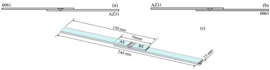
Figure 1.
Schematic of lap joint modes: (a) Al-Mg and (b) Mg-Al configurations and (c) dimensions of the tensile shear specimen.
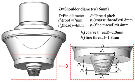
Figure 2.
Schematic of the tool with a variable-pitch thread pin.
After welding, cross-section samples for microstructural observation were cut perpendicularly to the welding direction, and then mechanically ground and etched with picric acid solution and 20% NaOH solution. The metallographic sample was analyzed under optical microscopes (OLYMPUS-DSX-WZ and OLYMPUS-BX53MRF-S, Tokyo, Japan) and a scanning electron microscope (JSM-7001F, JEOL, Tokyo, Japan) equipped with an energy dispersive X ray spectrometer (EDS), and IMCs was identified according to EDS data. Microhardness tests of representative specimens were performed using a Vickers microhardness tester (Wolpert Wilson-401MVD, Worcester, MA, USA) with a load of 100 g and dwell time of 15 s for measuring the Vickers microhardness (HV); the distance between each hardness indent was 0.5 mm. The tensile shear properties of the lap joints were determined in lap shear tests following the ASTM D1002-10 standard. Tensile shear tests were performed in a Shimadzu AG-X Plus universal testing machine (Tokyo, Japan). During the tensile process, the load was applied to the AS of the upper sheet. Test specimens (of width 15 mm) were cut from the lap joints perpendicularly to the welding direction, as shown in Figure 1c. The tensile shear strength of each specimen (in N/mm) was calculated by dividing the fracture load by the specimen width. The reported tensile shear strengths are the average values of three trials for each configuration. After the lap shear tests, the fracture positions of each lap joint were recorded. The fracture morphologies were observed using a scanning electron microscope (JEOL-JSM6501, JEOL, Tokyo, Japan).
3. Results
3.1. Joint Formations
Figure 3 shows the macro cross-sections of the FSLW joints of dissimilar metals (Al/Mg) welded in different lap configurations at different rotation speeds. In Configuration Al-Mg at 700 rpm, the SZ boundary was straight and smooth and the thick IMCs bands in the SZ were distributed in the Al matrix (Figure 3a). The original lap interface of the thermo-mechanically affected zone near the AS and the RS migrated upward, forming a hook and cold lap defect, respectively. However, in Configuration Mg-Al at the same rotation speed, the SZ boundary was complicated and tortuous, entangling a large number of Al and Mg alloy bands. The complex onion-ring structure indicates that an effective mechanical interlock formed in the SZ [27]. Such complex mechanical interlocking improves the external-load resistance of a joint [28,29]. In addition, the hook and cold lap formed in Configuration Mg-Al migrated upward over a certain distance before migrating into the SZ. The lap configuration altered the characteristics not only of the hook and cold lap, but also of the SZ; in particular, the degree of mechanical locking was higher in Configuration Mg-Al than in Configuration Al-Mg.
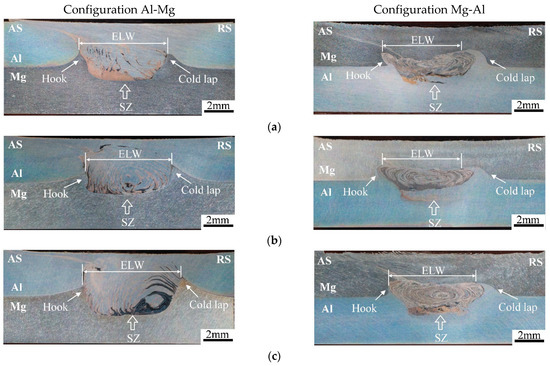
Figure 3.
Macro morphologies of the weld cross sections in different lap configurations formed at different rotation speeds. (a) 700 rpm; (b) 1100 rpm; (c) 1500 rpm.
In general, increasing the rotation speed of the tool increased the welding heat input, thereby improving the metal flow ability in the SZ [30]. In Configuration Al-Mg, the SZ exhibited no obvious onion-ring structures at 700 rpm, but onion-ring characteristics were observed at 1100 rpm. Meanwhile, onion ring structures were evidenced in the SZ of Configuration Mg-Al at 700 rpm, and became denser as the rotation speed increased. This onion-ring structure occurred by violent mixing of the two alloys, indicating that the mixing degree of the two alloys in the SZ was higher in Configuration Mg-Al than in Configuration Al-Mg.
In FSLW joints, the ELW is an important determiner of the shear strength of a joint, which defines the horizontal distance between the hook tip at the AS and the cold lap tip at the RS [31,32]. Its value is mainly determined by the migration behavior of the interface materials in the SZ (see Figure 4). In both lap configurations, increasing the rotation speed from 700 to 1100 rpm decreased the ELW, but when the rotation speed was further increased to 1500 rpm, the ELW recovered and reached its maximum. The high rotation speed of the tool promoted material flow in the SZ, increasing the ELW [33]. For any set of welding parameters, the ELW was always greater in the Configuration Al-Mg joint than in the Configuration Mg-Al joint.
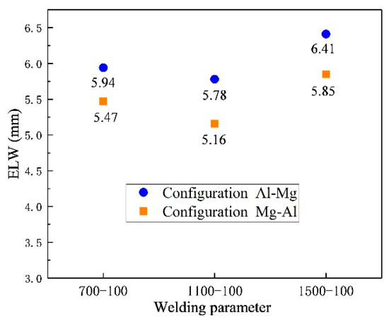
Figure 4.
Effective lap width of joints welded in different lap configurations at different rotation speeds.
3.2. Tensile Shear Strength
Figure 5 compares the tensile shear strengths of the joints with different lap configurations welded at different rotation speeds. For the same parameter settings, the tensile shear strength of the joint was stronger in Configuration Mg-Al than in Configuration Al-Mg. In both lap configurations, the tensile shear strength of the joint was maximized at 700 rpm (160.3 and 217 N/mm in the Al-Mg and Mg-Al configurations, respectively). The tensile shear performance of the joint welded in configuration Mg-Al was comparable to that of Ji et al. [15] after adding Zn foil (220 N/mm). As the rotation speed increased, the tensile shear strengths of both joints trended similarly to the ELW. Enlarging the ELW enhanced the tensile shear strength by increasing the crack propagation path [34]. However, the strength of the joint also depends on the amount of IMCs and the microstructure characteristics in the SZ. In general, the heat input is related to the welding parameters (rotation speed and welding speed) through a parameter called the heat index (HI) factor [4], defined as follows:
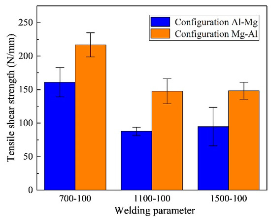
Figure 5.
Tensile shear strengths of the joints formed in different lap configurations at different rotation speeds.
Here, ω and v represent the rotation speed and welding speed of the tool, respectively. As the rotation speed increased from 700 to 1500 rpm, the HI increased and more IMCs formed in the SZ, deteriorating the joint performance [34]. Although the ELWs in the joints formed at 700 rpm were sub-maximal, the low heat input inhibited the emergence of IMCs, so the tensile shear strength was highest at this speed.
For the same parameter settings, the tensile shear strength of the joint was found to be stronger in the Mg-Al configuration than in the Al-Mg configuration. For dissimilar metals such as Al and Mg, the heat input is also affected by the lap configuration of the welded structure. For instance, the material properties (friction coefficient, liquation sensitivity, and deformability) of the materials [8,35,36], and the shoulder is the main point of heat generation. For the Al-Mg configuration, the shoulder of the welding tool is completely in contact with the Al alloy. Both friction heat and plastic deformation heat increased during the FSLW process because of the higher coefficient of friction and deformability, as well as the lower liquation sensitivity of the Al alloy [15]. For the joint welded in the Mg-Al configuration, a liquid-film forms more easily between the shoulder and the Mg alloy (which has high liquation sensitivity) [36]. This film decreases the friction coefficient and deformation resistance of materials in the SZ and thus decreases the friction heat and plastic deformation heat. The lower heat input is beneficial for decreasing the formation of IMCs and improving joint strength. In addition, the variation of the standard deviation of the joint welded in the Mg-Al configuration is smaller than that in the Al-Mg configuration at different rotating speeds. This may be a result of the formation of a large amount of IMCs, the distribution of which affects the fracture behavior of the welded Al-Mg joints, causing fluctuations in their tensile shear strength. For joints welded in the Mg-Al configuration, Al and Mg alloys form an effective mechanical interlocking structure, which has relatively little influence on the fracture behavior of the joint, such that the tensile shear strength of the joint is relatively stable under different parameters.
In subsequent experiments, the microstructure, IMCs characteristics, and microhardness of the SZ were investigated in the joints obtained at 700 rpm. The aim was to reveal the mechanism underlying the different tensile shear strengths of the joints formed in different lap configurations.
3.3. Microstructure and Microhardness
Figure 6 shows the macro- and micro-structures of the joint welded in the Al-Mg configuration at 700 rpm, and Figure 7 shows the SEM morphologies and EDS results in different micro regions. The IMCs generated in the joint appear as bright white regions in Figure 6b–f. The IMCs bands inside the SZ (Figure 6c) and cold lap (Figure 6d) were more than 60-μm wide. As shown in Figure 7d–e, the dark grey IMCs bands in the SZ were mainly Al3Mg2 (point 3 in Figure 7), indicating that constitutional liquation occurred during welding [37]. The IMCs was identified by calculating composition ratio of atoms from EDS data and reference to the published results [6,24]. Many studies have shown that IMCs cannot grow to such large sizes by solid-state diffusion alone [23,24,38]. During the welding process of Configuration Al-Mg, the liquation phase was generated at temperatures above the eutectic temperature (450 °C), and the eutectic reaction L→Al+Al3Mg2 occurred during cooling. In addition, the black structure (point 4 in Figure 7) around the Al3Mg2 bands was an Al-based solid solution.
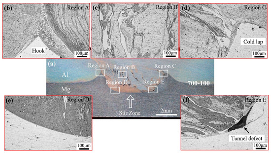
Figure 6.
Macrostructure and microstructure of the joint welded in Configuration Al-Mg at 700 rpm: (a) macro structure; (b) hook; (c) SZ; (d) cold lap; (e) SZ bottom at the AS; (f) SZ bottom at the RS.
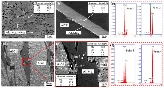
Figure 7.
SEM morphology and EDS results at various positions of the joint welded in Configuration Al–Mg at 700 rpm: (a) hook tip; (b) interface of the SZ bottom at the AS; (c) EDS results at points 1 and 2; (d) SZ; (e) magnified micrograph of (d); (f) EDS results of points 3 and 4.
At the tip of the hook defect (Figure 6b), a typical eutectic structure (Figure 7a) was observed. According to the EDS results (Figure 7c), the eutectic structure (point 1 in Figure 7) was mainly Al12Mg17+Mg, further confirming the occurrence of constitutional liquation. During the tensile shear test, those hard and brittle IMCs accelerated the crack propagation, thereby deteriorating the joint properties. The bottom interface of the SZ at the AS was flat and smooth (Figure 6e), indicating failure to form an effective mechanical interlocking structure. Examining panels b and c of Figure 7, the IMCs (Al3Mg2) were distributed as a 2.4-μm thick layer along the interface. The IMCs were concentrated around the tunnel defect observed at the bottom of the SZ at the RS (Figure 6f). This effect is mainly attributable to blockage of the plastic flow by the IMCs, which prevented the plastic metal from filling the cavity at the bottom of the SZ in sufficient time.
Figure 8 shows the macro- and micro-structures of the joint welded in the Mg-Al configuration at 700 rpm, and Figure 9 shows the SEM morphology and EDS results in different micro regions. In this sample, thin IMC layers appeared around the hook (Figure 8b) and cold lap (Figure 8d). During the FSLW process, the Al and Mg alloys in the SZ were largely plastically deformed by strong thermal-mechanical coupling, and intersected to form a complex onion-ring structure [16].
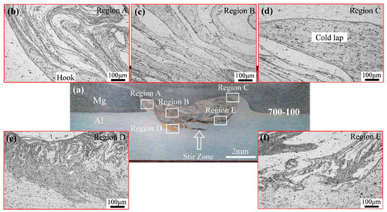
Figure 8.
Macrostructure and microstructure of the joint welded in Configuration Mg-Al at 700 rpm: (a) macro structure; (b) hook; (c) SZ; (d) cold lap; (e) SZ bottom at the AS; (f) SZ bottom at the RS.
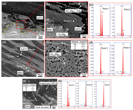
Figure 9.
SEM morphology and EDS results of the joint welded in Configuration Mg-Al at 700 rpm: (a) interface of SZ bottom at the RS; (b) magnified micrograph of (a); (c) EDS results of points 1 and 2; (d) SZ; (e) magnified micrograph of (d); (f) EDS results of points 3 and 4; (g) hook structure at SZ bottom at the AS; (h) EDS results of points 5, 6 and 7.
Figure 8c shows the onion ring structure inside the SZ. Three kinds of banded structures with different contrasts appeared in the onion ring (Figure 9d,e). As shown in the EDS results (Figure 9f), the regions of deepest and lightest contrast constituted Mg and Al alloy, respectively. The EDS result of Figure 9h confirmed the banded flocculent structure (point 5) as Al12Mg17. When the local temperature inside the SZ reached the eutectic temperature (437 °C), the contact interface between the Al and Mg bands began to liquefy, forming band liquation films which precipitated flocculent Al12Mg17 during subsequent cooling. Therefore, the Mg alloy bands, flocculent Al12Mg17 bands, and a small proportion of the Al alloy bands intersected in the SZ. Note that the bottom interface of the SZ at the RS was very tortuous, forming a complex mechanical interlocking structure (Figure 8f). The Al alloy and bulk IMCs at the interface bit into each other (Figure 9a,b), thereby increasing the strength of the joint [39]. As seen in Figure 9c, the bulk IMCs generated near the Al side were mainly Al3Mg2, and the flocculent structure generated near the Mg side was eutectic Al12Mg17+Mg, consistent with a previous study [24]. Figure 9g is a magnified observation of the hook structure in Figure 8e, showing fine broken and dispersed IMCs through the structure. As shown in the EDS results (Figure 9h), this black structure was an Al-based solid solution with a Mg content of 4.3 at.%. The 6061 Al alloy (point 7 in Figure 9) contained only 1.9 at.% Mg, indicating that the black structures were mainly formed by solid-state diffusion during the welding process.
Figure 10 and Figure 11 show the results of microhardness tests of joints welded in the Al-Mg and Mg-Al configurations at 700 rpm. The figures show that the hardness values of the SZ of two joints are approximately 60 HV, whereas the hardness of SZ in the Al-Mg configuration is much lower than that of the 6061-T6 aluminum alloy (approximately 97 HV); this may be attributed to the softening of the aluminum alloy during welding. Notably, the microhardness profiles reveal large fluctuations at the Al12Mg17+Mg eutectic structure of the hook tip (Figure 10c) and Al3Mg2 bands inside the SZ (Figure 10d), which are 177.3 HV and 130.8 HV, respectively. For the joint welded in the Mg-Al configuration, large fluctuations in hardness were also observed. The hardness of the mechanical interlocking structure composed of Al12Mg17 bands and Mg alloy bands around the hook (Figure 11c) was up to 132.2 HV, whereas the hardness of the flocculent Al12Mg17 inside the SZ (Figure 11d) was up to 118.1 HV. A large amount of hard and brittle Al3Mg2 bands were formed in the SZ of the Al-Mg configuration at 700 rpm, leading to the preferential initiation of cracks at the interface during tensile shear test. As a result, the mechanical properties of joints welded in the Al-Mg configuration are weaker than those welded in the Mg-Al configuration.
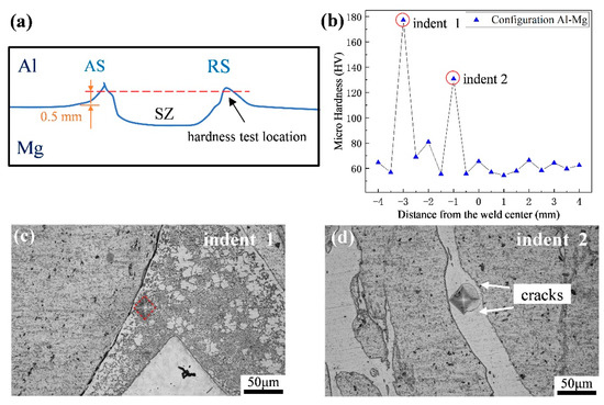
Figure 10.
Results of microhardness tests of the joint welded in Configuration Al-Mg at 700 rpm: (a) schematic diagram of hardness test location; (b) microhardness profiles; (c) optical micrograph at indent 1; (d) optical micrograph at indent 2.
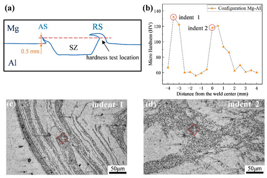
Figure 11.
Results of microhardness tests of the joint welded in Configuration Mg-Al at 700 rpm: (a) schematic diagram of hardness test location; (b) microhardness profiles; (c) optical micrograph at indent 1; (d) optical micrograph at indent 2.
3.4. Fracture Morphology
Figure 12 and Figure 13 show the macro- and micro-structures of the cross sections of the failure joints welded in the Al-Mg and Mg-Al configurations at 700 rpm. Rao et al. [25] reported the formation of main and minor cracks during the loading process. The main cracks led to final failure of the joint. During the loading process of the present joint, minor cracks were generated at the hook defect and propagated upward (Figure 12a and Figure 13a). As the load increased, the strengthening bending moment initiated the main crack at the cold lap defect. This crack propagated along the interface at the bottom of the SZ, and eventually fractured the lap joint. In Configuration Al-Mg, cracks were initiated in the IMCs around the hook and cold lap defects (Figure 12b,c). In Configuration Mg-Al, the main cracks did not converge with the minor cracks along the contour of the SZ, but extended into the Al matrix (Figure 13b). Meanwhile, cracks at the RS propagated along the cold lap defect interface, increasing the crack propagation path and thereby improving the performance (Figure 13c). As shown in Figure 12d and Figure 13d, the crack propagation path along the bottom interface of the SZ in Configuration Al-Mg was relatively smooth and straight. In contrast, the main crack propagation path along the bottom of the SZ in Configuration Mg-Al was branched with many secondary cracks. The complex interlocking structure hindered the propagation of the main crack, creating a curved and tortuous propagation path.
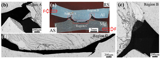
Figure 12.
Macro- and micro-structures of the cross section of the failure joint welded in Configuration Al-Mg at 700 rpm: (a) macro-structure; (b) hook; (c) cold lap; (d) bottom of the SZ.
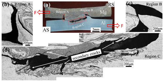
Figure 13.
Macro- and micro-structures of the cross section of the failure joints welded in Configuration Mg-Al at 700 rpm: (a) macro-structure; (b) hook; (c) cold lap; (d) bottom of the SZ.
Figure 14 shows the fracture morphologies of both joint configurations. In Configuration Al-Mg, the fracture surface was relatively flat, showing an arc-like material flow. The cracks propagated rapidly through the smooth IMCs layer at the bottom surface of the SZ (Figure 14b), which mainly explains the poor performance of the joint welded in this configuration. In contrast, Configuration Mg-Al presented a relatively rough fracture surface (Figure 14c) with a multitude of secondary cracks (Figure 14d). The secondary cracks were enforced by the complex interlocking structure at the bottom of the SZ, which hindered the propagation of the main cracks. By this mechanism, the joint performance was improved.
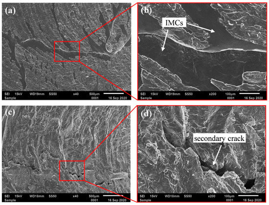
Figure 14.
Fracture morphologies of the joints welded in different lap configurations at 700 rpm: (a) Configuration Al-Mg; (b) magnified micrograph of (a); (c) Configuration Mg-Al; (d) magnified micrograph of (c).
4. Discussion
To further reveal the material flow behaviors in the SZs of the two lap configurations, the FSLW process was simplified to three stages (see Figure 15). In Stage 1, the pin plunged into the upper sheet but did not penetrate the lower sheet. In Stage 2, the pin entered the lower sheet but the shoulder did not touch the upper sheet. In Stage 3, the shoulder touched the upper sheet, and stable welding began.

Figure 15.
Schematic of material flows in different lap configurations: (a) Configuration Al-Mg; (b) Configuration Mg-Al.
In Configuration Al-Mg, the pin thread drove the downward migration of the Al alloy during the first stage. As the plunge depth of the pin increased, the upper (Al alloy) and lower (Mg alloy) sheets contacted the coarse and fine threads of the pin, respectively (Stage 2). As the fine thread possessed a larger surface area than the coarse thread, it generated a large frictional heat when contacting the Mg alloy. However, owing to its high friction coefficient and good deformability, Al flows more easily than Mg. The rapid downward flow of Al alloy squeezed the Mg alloy, inhibiting its upward migration; consequently, the original lap interface arched upward. During the Stage 3, the shoulder plunged into the upper sheet of the Al alloy, further increasing the frictional heat generation and improving the flow ability of the Al alloy. When the SZ was almost filled with Al alloy, the mixing degree of Al/Mg was reduced and an effective interlocking structure could not be formed (Figure 15a).
As the plunge depth of the pin increased in Configuration Mg-Al, the fine threaded part of the pin eventually contacted the lower Al sheet. The increased contact area between the Al alloy and the fine-threaded pin part improved the flow ability of the Al alloy at the bottom of the SZ. The upper Mg sheet then squeezed the lap interface and migrated downward, forcing the upward migration of the lap interface bordering the lower Al sheet. This mechanism caused the curvature of the original lap interface in Stage 2. During the Stage 3, a liquation film was easily formed between the Mg alloy (which has high liquation sensitivity) [36] and the shoulder. The lubricating effect of the liquation film reduced the frictional heat generated between the shoulder and the Mg alloy, weakening the flow ability of the Mg alloy. This weakening effect reduced the difference in flow abilities between the Al and Mg alloys, enabling their violent mixture in the SZ to form the onion-ring structure. Within the vortex layer, the hook defect and cold lap defect migrated into the SZ, and the bottom interface of the SZ became more tortuous (Figure 15b). The high tensile shear strength of the joint welded in the Mg-Al configuration was attributed to the mechanical interlocking structure. From the research result above, the variable-pitch tool proposed in this paper can effectively enhance the vertical material flow, promote the mixing of dissimilar metals, and hence improve the joint strength.
5. Conclusions
In this study, a 3-mm-thick 6061-T6 aluminum alloy was welded with a sheet (AZ31 magnesium alloy) by friction stir lap welding (FSLW) using a tool with a variable-pitch thread pin (coarse-threaded in the upper part; fine-threaded in the lower part). This paper investigated the effects of the tool with a variable-pitch thread pin on the material flow behavior, IMCs distribution and tensile shear strength of joints welded in different configurations under different welding parameters. The significant conclusions are given below.
(1) In Configuration Al-Mg, the Al alloy around the coarse-threaded part of the pin near the shoulder was easily driven downward, and the stirred zone was primarily composed of Al alloy. In this case, the dissimilar metals were poorly mixed and the bottom interface remained smooth and straight. In Configuration Mg-Al, the Al alloy was driven downward under the action of the fine-threaded pin part, then reversed direction at the bottom of the stirred zone. Finally, it mixed violently with the Mg alloy migrating downward under the action of the coarse-threaded pin part. The enhanced mixing degree of Al/Mg formed a complex mechanical interlocking structure.
(2) The frictional heat generation was higher in Configuration Al-Mg than in Configuration Mg-Al; consequently, large amounts of IMCs were formed inside the SZ of Configuration Al-Mg. The IMCs (mainly constituting Al3Mg2) were continuously distributed along the bottom interface of the SZ. In Configuration Mg-Al, the flocculent Al12Mg17 bands, Mg alloy bands, and minor Al alloy bands intersected in the SZ, forming a complex onion-ring structure, and the IMCs (mainly constituting Al12Mg17) were intermittently distributed along the bottom interface of the SZ.
(3) The maximum tensile shear strengths of the joints welded in Configurations Al-Mg and Mg-Al at 700 rpm were 160.3 and 217 N/mm, respectively. The higher tensile shear strength in Configuration Mg-Al was mainly attributable to the less IMCs and the complex mechanical interlocking structure in the SZ of this configuration.
Author Contributions
Conceptualization, C.H., C.Q. and Z.Z.; methodology, C.Q., N.T. and Z.Z.; software, J.W. and H.Z.; validation, C.Q. and Z.Z.; investigation, C.Q. and Z.Z.; writing—original draft preparation, C.H., C.Q. and Z.Z.; writing—review and editing, C.H., C.Q. and Z.Z.; supervision, C.H. and G.Q.; project administration, N.T.; funding acquisition, G.Q. All authors have read and agreed to the published version of the manuscript.
Funding
This work was funded by the Project of Promoting Talents in Liaoning Province (No. XLYC1808038) and the National Key Research and Development Program of China (No. 2016YFB1200506-12).
Conflicts of Interest
The authors declare no conflict of interest in this work.
References
- Heinz, A.; Haszler, A.; Keidel, C.; Moldenhauer, S.; Miller, W.S. Recent development in aluminum alloys for aerospace application. Mater. Sci. Eng. A 2000, 280, 102–107. [Google Scholar] [CrossRef]
- Mordike, B.L.; Ebert, T. Magnesium properties-Applications-Potential. Mater. Sci. Eng. A 2001, 302, 37–45. [Google Scholar] [CrossRef]
- Liu, H.; Chen, Y.; Yao, Z.; Lou, F. Effect of Tool Offset on the Microstructure and Properties of AA6061/AZ31B Friction Stir Welding Joints. Metals 2020, 10, 546. [Google Scholar] [CrossRef]
- Mishra, R.S.; Ma, Z.Y. Friction stir welding and processing. Mater. Sci. Eng. R 2010, 50, 1–278. [Google Scholar] [CrossRef]
- Zhang, Z.; He, C.; Li, Y.; Yu, L.; Zhao, S.; Zhao, X. Effects of ultrasonic assisted friction stir welding on flow behavior, microstructure and mechanical properties of 7N01-T4 aluminum alloy joints. J. Mater. Sci. Technol. 2020, 43, 1–13. [Google Scholar] [CrossRef]
- Lv, X.Q.; Wu, C.S.; Padhy, G.K. Diminishing intermetallic compound layer in ultrasonic vibration enhanced friction stir welding of aluminum alloy to magnesium alloy. Mater. Lett. 2017, 203, 81–84. [Google Scholar] [CrossRef]
- Yan, J.; Xu, Z.; Li, Z.; Li, L.; Yang, S. Microstructure characteristics and performance of dissimilar welds between magnesium alloy and aluminum formed by friction stirring. Scr. Mater. 2005, 53, 585–589. [Google Scholar] [CrossRef]
- Fu, B.; Qin, G.; Li, F.; Meng, X.; Zhang, J.; Wu, C. Friction stir welding process of dissimilar metals of 6061-T6 aluminum alloy to AZ31B magnesium alloy. J. Mater. Process. Technol. 2015, 218, 38–47. [Google Scholar] [CrossRef]
- Liu, H.; Zhao, Y.; Hu, Y.; Chen, S.; Lin, Z. Microstructural characteristics and mechanical properties of friction stir lap welding joint of Alclad 7B04-T74 aluminum alloy. Int. J. Adv. Manuf. Technol. 2015, 78, 1415–1425. [Google Scholar] [CrossRef]
- Chen, Y.C.; Nakata, K. Friction stir lap joining aluminum and magnesium alloys. Scr. Mater. 2008, 58, 433–436. [Google Scholar] [CrossRef]
- Liu, H.; Hu, Y.; Peng, Y.; Dou, C.; Wang, Z. The effect of interface defect on mechanical properties and its formation mechanism in friction stir lap welded joints of aluminum alloys. J. Mater. Process. Technol. 2016, 238, 244–254. [Google Scholar] [CrossRef]
- Lee, C.; Lee, W.; Kim, J.; Choi, D.; Yeon, Y.; Jung, S. Lap joint properties of FSWed dissimilar formed 5052 Al and 6061 Al alloys with different thickness. J. Mater. Sci. 2008, 43, 3296–3304. [Google Scholar] [CrossRef]
- Xu, W.; Liu, J.; Luan, G.; Dong, C. Temperature evolution, microstructure and mechanical properties of friction stir welded thick 2219-O aluminum alloy joints. Mater. Des. 2009, 30, 1886–1893. [Google Scholar] [CrossRef]
- Zhu, R.; Gong, W.; Cui, H. Temperature evolution, microstructure, and properties of friction stir welded ultra-thick 6082 aluminum alloy joints. Int. J. Adv. Manuf. Technol. 2020, 108, 331–343. [Google Scholar] [CrossRef]
- Ji, S.; Niu, S.; Liu, J.; Meng, X. Friction stir lap welding of Al to Mg assisted by ultrasound and a Zn interlayer. J. Mater. Process. Technol. 2018, 267, 141–151. [Google Scholar] [CrossRef]
- Ji, S.; Li, Z.; Zhang, L.; Zhou, Z.; Chai, P. Effect of lap configuration on magnesium to aluminum friction stir lap welding assisted by external stationary shoulder. Mater. Des. 2016, 100, 160–170. [Google Scholar] [CrossRef]
- Mehta, K.; Carlone, P.; Astarita, A.; Scherillo, F.; Rubino, F. Conventional and cooling assisted friction stir welding of AA6061 and AZ31B alloys. Mater. Sci. Eng. A 2019, 759, 252–261. [Google Scholar] [CrossRef]
- Thomas, W.M.; Staines, D.G.; Norris, I.M. Friction stir welding tools and developments. Weld. World 2003, 47, 10–17. [Google Scholar] [CrossRef]
- Sun, Z.; Wu, C. Influence of tool thread pitch on material flow and thermal process in friction stir welding. J. Mater. Process. Technol. 2020, 275, 116281. [Google Scholar] [CrossRef]
- Nia, A.A.; Omidvar, H.; Nourbakhsh, S.H. Investigation of the effects of thread pitch and water cooling action on the mechanical strength and microstructure of friction stir processed AZ31. Mater. Des. 2013, 52, 615–620. [Google Scholar]
- Ji, S.; Li, Z.; Zhou, Z.; Wu, B. Effect of Thread and Rotating Speed on Material Flow Behavior and Mechanical Properties of Friction Stir Lap Welding Joints. J. Mater. Eng. Perform. 2017, 26, 5085–5096. [Google Scholar] [CrossRef]
- Yue, Y.; Li, Z.; Ji, S.; Huang, Y.; Zhou, Z. Effect of Reverse-threaded Pin on Mechanical Properties of Friction Stir Lap Welded Alclad 2024 Aluminum Alloy. J. Mater. Sci. Technol. 2016, 32, 671–675. [Google Scholar] [CrossRef]
- Firouzdor, V.; Kou, S. Al-to-Mg Friction Stir Welding: Effect of Positions of Al and Mg with Respect to the Welding Tool. Weld. J. 2009, 88, 213–224. [Google Scholar]
- Firouzdor, V.; Kou, S. Formation of Liquid and Intermetallics in Al-to-Mg Friction Stir Welding. Met. Mater. Trans. A 2010, 41, 3238–3251. [Google Scholar] [CrossRef]
- Rao, H.M.; Ghaffari, B.; Yuan, W.; Jordon, J.B.; Badarinarayan, H. Effect of process parameters on microstructure and mechanical behaviors of friction stir linear welded aluminum to magnesium. Mater. Sci. Eng. A 2016, 651, 27–36. [Google Scholar] [CrossRef]
- Tan, S.; Zheng, F.; Chen, J.; Han, J.; Wu, Y.; Peng, L. Effects of process parameters on microstructure and mechanical properties of friction stir lap linear welded 6061 aluminum alloy to NZ30K magnesium alloy. J. Magnes. Alloy. 2017, 5, 56–63. [Google Scholar] [CrossRef]
- Liu, Z.; Yang, K.; Ji, S. Reducing Intermetallic Compounds of Mg/Al Joint in Friction Stir Lap Welding. J. Mater. Eng. Perform. 2018, 27, 5605–5612. [Google Scholar] [CrossRef]
- Yamamoto, N.; Liao, J.; Watanabe, S.; Nakata, K. Effect of Intermetallic Compound Layer on Tensile Strength of Dissimilar Friction-Stir Weld of a High Strength Mg Alloy and Al Alloy. Mater. Trans. 2009, 50, 2833–2838. [Google Scholar] [CrossRef]
- Murr, L.E.; Li, Y.; Flores, R.D.; Trillo, E.; McClure, J.C. Intercalation vortices and related microstructural features in the friction-stir welding of dissimilar metals. Mater. Res. Innov. 1998, 2, 150–163. [Google Scholar] [CrossRef]
- Rhodes, C.G.; Mahoney, M.W.; Bingel, W.H.; Spurling, R.A.; Bampton, C.C. Effects of friction stir welding on microstructure of 7075 aluminum. Scr. Mater. 1997, 36, 69–75. [Google Scholar] [CrossRef]
- He, C.; Zhang, Z.; Li, Y.; Wei, J.; Zhai, M.; Zhao, S.; Zhao, X. Interface Characteristics and Mechanical Properties of Ultrasonic-Assisted Friction Stir Lap Welded 7075-T6 Aluminium Alloy. Materials 2020, 13, 5335. [Google Scholar] [CrossRef] [PubMed]
- Park, S.; Yoon, T.; Kang, C. Effects of the shoulder diameter and weld pitch on the tensile shear load in friction-stir welding of AA6111/AA5023 aluminum alloys. J. Mater. Process. Technol. 2017, 241, 112–119. [Google Scholar] [CrossRef]
- Yazdanian, S.; Chen, Z.W.; Littlefair, G. Effects of friction stir lap welding parameters on weld features on advancing side and fracture strength of AA6060-T5 welds. J. Mater. Sci. Technol. 2012, 47, 1251–1261. [Google Scholar] [CrossRef]
- Niu, S.; Ji, S.; Yan, D.; Meng, C.; Xiong, X. AZ31B/7075-T6 alloys friction stir lap welding with a zinc interlayer. J. Mater. Process. Technol. 2018, 263, 82–90. [Google Scholar] [CrossRef]
- Zettler, R.; Silva, A.; Rodrigues, S.; Blanco, A.; Santos, J. Dissimilar Al to Mg Alloy Friction Stir Welds. Adv. Eng. Mater. 2006, 8, 415–421. [Google Scholar] [CrossRef]
- Yang, Y.K.; Dong, H.; Kou, S. Liquation tendency and liquid-film formation in friction stir spot welding. Weld. J. 2008, 87, 202–211. [Google Scholar]
- Sato, Y.S.; Park, S.H.C.; Michiuchi, M.; Kokawa, H. Constitutional liquation during dissimilar friction stir welding of Al and Mg alloys. Scr. Mater. 2004, 50, 1233–1236. [Google Scholar] [CrossRef]
- Kostka, A.; Coelho, R.S.; Santos, J.D.; Pyzalla, A.R. Microstructure of friction stir welding of aluminium alloy to magnesium alloy. Scr. Mater. 2009, 60, 953–956. [Google Scholar] [CrossRef]
- Wei, Y.; Li, J.; Xiong, J.; Huang, F.; Zhang, F. Microstructures and mechanical properties of magnesium alloy and stainless steel weld-joint made by friction stir lap welding. Mater. Des. 2012, 33, 111–114. [Google Scholar] [CrossRef]


Publisher’s Note: MDPI stays neutral with regard to jurisdictional claims in published maps and institutional affiliations. |
© 2020 by the authors. Licensee MDPI, Basel, Switzerland. This article is an open access article distributed under the terms and conditions of the Creative Commons Attribution (CC BY) license (http://creativecommons.org/licenses/by/4.0/).