Article

Microstructure and Fatigue Behavior of 2205/316L Stainless Steel Dissimilar Welded Joints

by
Saúl Leonardo Hernández-Trujillo
1,2,
Victor Hugo Lopez-Morelos
1,*,
Marco Arturo García-Rentería
3,
Rafael García-Hernández
1,
Alberto Ruiz
1 and
Francisco Fernando Curiel-López
1
1
Instituto de Investigación en Metalurgia y Materiales, Universidad Michoacana de San Nicolás de Hidalgo, Edificio “U”, Ciudad Universitaria, 58030 Morelia, Mexico
2
Instituto de Investigación y Posgrados para la Interculturalidad, Universidad Intercultural Indígena de Michoacán, Finca “La Tzípecua” km 3 Carretera Pátzcuaro-Erongaricuaro, 61614 Pátzcuaro, Mexico
3
Facultad de Metalurgia, Universidad Autónoma de Coahuila, Carretera 57 km 5, 25710 Monclova, Mexico
*
Author to whom correspondence should be addressed.
Metals 2021, 11(1), 93; https://doi.org/10.3390/met11010093
Submission received: 16 December 2020 / Revised: 29 December 2020 / Accepted: 31 December 2020 / Published: 5 January 2021
(This article belongs to the Special Issue Dissimilar Material Welding and Joining)

Abstract

:
The relation among microstructure and fatigue behavior of 2205/316L stainless steel dissimilar welded joints was investigated. Plates of 6.35 mm in thickness with a single-V joint configuration were gas metal arc welded (GMAW) in a single pass by feeding at 6 m/min an ER2209 filler wire with a heat input of 1.2 kJ/mm. Grain growth in the high temperature-heat affected zone (HT-HAZ) occurred mostly at the mid-height of the plates, delimiting the width of this region up to ~1.28 and ~0.73 mm of the 2205 and 316L plates, respectively. Dilution of the 316L plate with the ER2209 filler altered the solidification mode in this side of the weld and led to a significant content of austenite along the fusion line. Fatigue tests were performed using sinusoidal waveform at room temperature applying uniaxial cyclic loading, between constant stress limits within the elastic deformation of tension and compression (Δσ) with stress ratio R = −0.3. With stress ranges of 98% and 95% the fatigue specimens rapidly failed in much less than 106 cycles. The failure crack initiated at the surface of the 316L in the HT-HAZ near the weld toe. Surface analyses of unbroken specimens before and after fatigue testing revealed a significant increment in roughness of the 316L base material owing to the formation of intrusions and extrusions.

Graphical Abstract

1. Introduction

Engineers face the need to join different alloys to optimize the design and exploiting the individual characteristics of the new materials. Welding of dissimilar materials has increased considerably in the industry due to the great benefits that include improvements in design flexibility and cost reduction. In order to take advantage of the assets of alloys with distinct characteristics, dissimilar welding provides a viable alternative for the best performance in service. However, it is very important to make an appropriate selection of the filler metal and welding process to achieve this goal [1,2,3,4,5,6,7].
In virtue of the different nature of the applications, the study of the mechanical properties of stainless steels, either quasi-static or dynamics, are topics of great scientific and technological relevance. The most popular and versatile method for joining components and assembling rigs at an industrial level is arc fusion welding. However, the heat input of the process gives rise to localized heterogeneities in the microstructure and mechanical properties of the base metal (BM), weld metal (WM) and heat affected zone (HAZ), leading to a complex mechanical behavior of the welded component when subjected to different loads. The mechanical strength of the welded joints represents a very important factor in the estimation of the useful life of containers and pressurized pipes, which determines the resistance of the entire structure. In most of the cases, the failure of welded joints induced by fatigue starts at the toe of the weld bead, and the failure is caused by the propagation of semi-elliptical cracks on the surface and propagates across the base material [8,9].
Duplex stainless steels (DSSs) have been successfully used in oil pipelines, gas fuel, chemical, petrochemical and marine transportations as well as in power generation plants due to their excellent mechanical properties and resistance to crevice and pitting corrosion. This class of alloys is approximately 1.5 times more resistant than common austenitic stainless steels owing to the approximate 50/50 ratio of ferrite (δ) and austenite (γ) phases present in their microstructure. DSSs are very attractive to the industry due to its cost/properties ratio because the lower content of nickel as compared to austenitic grades, saves between 70 and 210 kg of Ni per metric ton of steel [2]. In the counterpart, 316L austenitic stainless steel (ASS) is widely used in a vast number of applications because it has good resistance to creep and fatigue properties making it a suitable candidate as a structural material with good corrosion resistance [10]. Due to the constant operation under extreme demand and the periodic routine maintenance carried out in the oil, gas, power plants or aircraft engines, all together contribute to their components experiencing fatigue [11].
The use of stainless steels with low carbon grade, like 316L, extends the time available before chromium carbide precipitation begins during cooling in secondary processing like welding, but this does not mean that 316L will be immune to sensitization during long-term exposure in the critical temperature range of 500–800 °C in service [12,13]. Even with the reduction in carbon content, when 316L is exposed to high temperatures, it is susceptible to experiencing various metallurgical problems (e.g., precipitation of detrimental phases). In addition, excessive heat input during arc fusion welding may extend the time at high temperature in the HAZ (>500 °C) increasing the likelihood of intermetallic sigma (σ), chi (χ) and Laves (η) phases precipitating along with undesirable carbides of the type M23C6 [5,10,14,15,16].
According to a number of reports [17,18,19], ASSs represent between 60 to 75 percent of the total usage of corrosion resistant metallic materials. Structural applications of a variety of components demand a better understanding of their mechanical behavior because most of the breaks down occur due to fatigue. When the weld metal solidifies and cools down to room temperature, it contracts resulting in a state of high residual tensile stresses, while in the base metal compression residual stresses are induced. In this manner, arc fusion welding alters the fatigue crack propagation characteristics in a welded joint as a consequence of these residual stresses [19].
Engineering structures around the world are commonly subjected to a wide range of distinct loading conditions, including, but not limited to, cyclical loads due to operating conditions, secondary loads due to residual stresses as well as static charges by their own weight. In the design of components that undergo cyclic loads, the prediction of fatigue life and industrial safety are very important and complex [20,21]. Due to the complicated nature and the large number of factors that influence fatigue life, up to today, there is not a unified approach available that can treat all fatigue problems. An additional concern relies on the fact that engineering components may contain manufacturing defects and quite often the geometric discontinuities in the surface are the starting points in failures due to low cycle fatigue [22].
Recent studies of the mechanical strength of 2205/316L stainless steels dissimilar welded joints have shown that the specimens fail in the side of the 316L ASS [2,3,6,23,24,25,26]. When a DSS filler wire is used for welding, the mechanical strength in the welded zone is higher as compared to the monolithic 316L ASS. This may be due to differences in the chemical composition that promote the dual-phase nature and a stronger solid solution strengthening mechanism as mentioned in some publications [2,3,6,23]. The fatigue damage in grains of 2205 DSS and 316L ASS results in the formation of persistent slip markings consisting of extrusions and intrusions, which are very important features of early fatigue damage of polycrystalline materials because fatigue cracks nucleate at these locations [27,28,29]. In this scenario, the objective of this study is to evaluate the fatigue life of the 2205/316L stainless steel dissimilar welded joints.

2. Materials and Methods

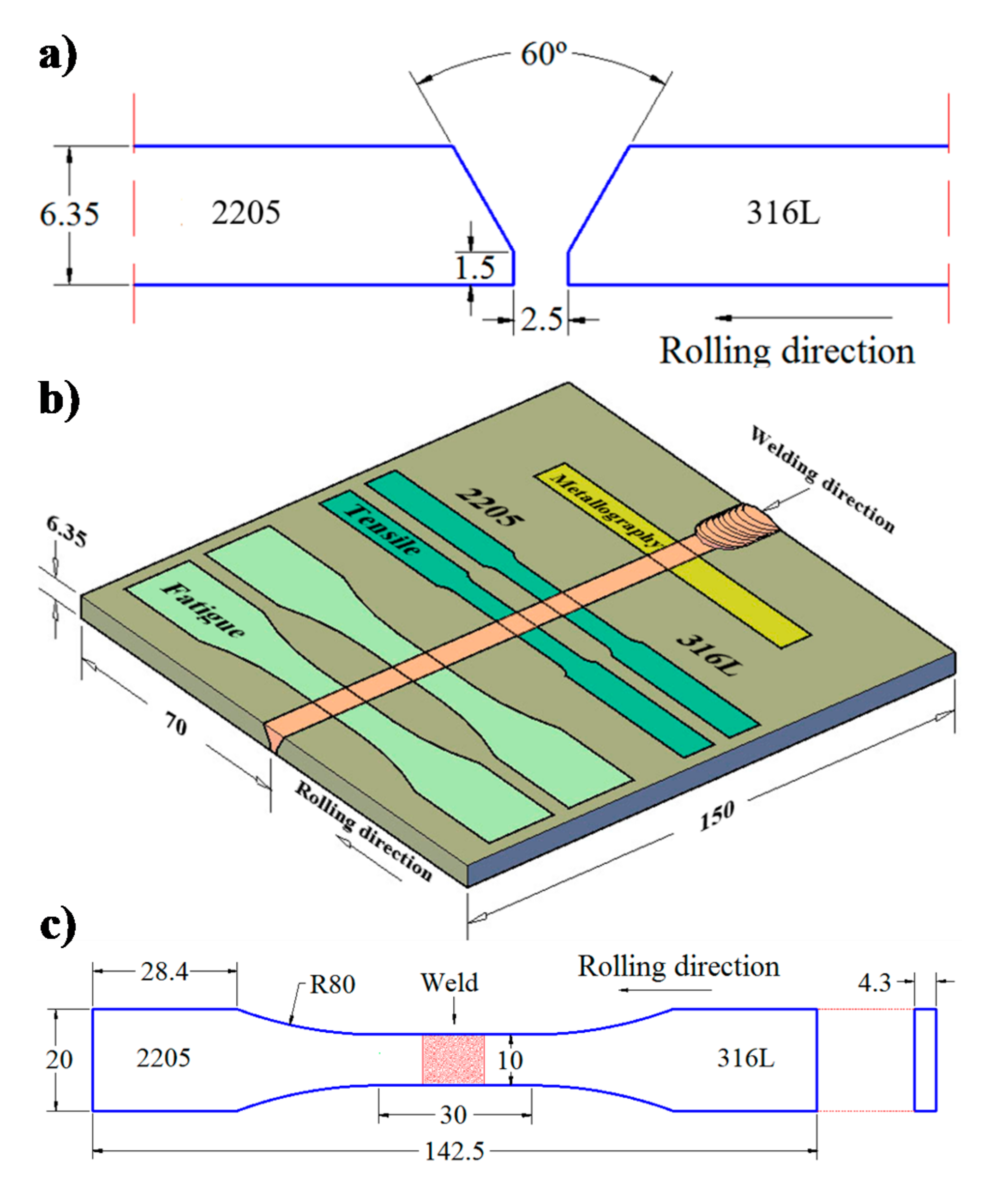
2.1. Materials and Welding

The rectangular plates employed in this study were 2205 DSS (UNS 31803) and 316L ASS (UNS S31603) with dimensions of 150 mm by 70 mm by 6.35 mm. The plates were machined to a single-V groove butt joint configuration as shown in Figure 1a. Table 1 shows the chemical composition of the stainless steel plates and filler according to the suppliers. These compositions were confirmed by optical emission spectrometry analysis (Q4 TASMAN, Bruker AXS GmbH, Karlsruhe, Germany). The last column of Table 1 also shows the Creq/Nieq ratio as calculated based on the WRC-1992 diagram [30]. The thermo-mechanical data sheet of the suppliers reported that the plates were processed with a solution annealing treatment at 1050 °C for 5 min followed by water quenching.
The welding process was carried out semi-automatically in a sole welding pass, normal to the rolling direction of the plates in the as-received condition, using the gas metal arc welding (GMAW) process with direct current electrode positive. An AWS ER2209 filler wire of 1.2 mm in diameter was fed at 6 m/min shielded with a special gas mixture AWS SG-ANO-3/2 (95% Ar + 3% N2 + 2% O2) flowing at 18.8 L/min. The torch was displaced normal to the plates at 3.6 mm/s with a stick out of 10 mm. The welding parameters were 24 V and 240 A to restrict the heat input to 1.2 kJ/mm considering an efficiency of 75% for the GMAW process [31].

2.2. Microstructural Characterization

A sample was taken for microstructural characterization as shown in Figure 1b. Scanning electron microscopy (SEM, JSM 6400, Jeol Ltd., Tokio, Japan) and optical microscopy (OM, Zeiss Axio Observer 7 Materials, Carl Zeiss Microscopy, Oberkochen, Germany) were used to characterize the microstructure of the welded joints. Standard metallographic techniques were used for grinding and polishing the samples whereas chemical etching with Glyceregia reagent (15 mL HCl + 10 mL Glycerol + 5 mL HNO3) was carried out. Besides, color metallography with Beraha’s tint etch was made by dipping the sample into solutions of 10 mL HCl + 90 mL water + 0.03 g K2S2O5 + 0.02 g NH4FHF and 20 mL HCl + 80 mL water + 0.03 g K2S2O5 + 0.02 g NH4FHF to color ferrite and austenite, respectively. The solutions were at room temperature and the immersion of the sample into the solutions lasted for up to 120 s. The color produced by these etchants varies with the composition and may be different depending on the phase orientation, temperature, time, alloy composition and treatment, making color discrimination somewhat unreliable unless conditions are rigorously controlled [32]. Area measurements, weld metal dilution and phase quantifications were carried out using image analysis software (SigmaScan Pro, Version 5.0, Systat Software Inc., San Jose, CA, USA). Chemical compositional analyses were performed in the SEM by energy dispersive X-ray spectroscopy (EDX, XFlash Detector 6|10, Bruker AXS GmbH, Berlin, Germany).
Scanning of the transverse profile of the welded joint was performed with a Fischer Feritoscope FMP30 (Helmut Fischer GmbH, Sindelfingen, Germany). The instrument was calibrated with standards prior to measuring. A map of the ferrite variation was made by measuring the ferrite percentage in an area of 5 mm by 23 mm in height and length, respectively, composed by 6 horizontal lines, each one containing 24 punctual measurements separated 1 mm between them. In the weld reinforcement, another horizontal line of 9 punctual measurements was done. Thus, the scanned area covered the BM, HAZ and fusion zone (FZ) with 153 punctual measurements.

2.3. Tensile Testing

Tensile tests were performed using a 100 kN Landmark MTS load frame servohydraulic testing machine Model 370 (MTS Systems Corporation, Eden Prairie, MN, USA) and a FlexTest-40 controller with TestSuite Multipurpose Elite Software™ (MTS Systems Corporation, Eden Prairie, MN, USA). The cross head speed employed was 0.016 mm/s. Standard sub-size dog bone shape specimens from the as-received base materials and welded joint were machined, longitudinally to the rolling direction, in a computer numerical control (CNC) milling machine (Viwa S. A. de C. V., VF3KM400, Zapopan, Jalisco, México), according to the specifications of the ASTM E8-04 standard [33]. The axial deformation was measured during the tests with a MTS 634.31F-24 extensometer with a gauge length of 20 mm. The weld bead was in the middle of the gauge length of the specimens as illustrated in Figure 1b. The machined surfaces were ground with SiC emery paper up to 2000-grit in order to reduce surface imperfections and roughness in the gauge length. The yield stress was determined using the 0.2% offset criterion. Average Vickers microhardness values were measured with a computer controlled Mitutoyo HM-220B Vickers microhardness tester in the base materials by applying a load of 100 g during 15 s (Mitutoyo America Corporation, IL, USA).

2.4. Fatigue Testing

The CNC precision machining of the fatigue specimens from the dissimilar welded joint was carried out according to the dimensions and geometry specified by the ASTM E466-96 standard [34] as shown in Figure 1c. The depth of milling was reduced when the final dimensions of the specimens approached in order to avoid the possible introduction of residual stresses during machining. The fatigue specimens were mirror-like polished, excepting the grip sections, longitudinally to the rolling direction to eliminate machining imperfections and reduce roughness. Accurate data average surface roughness (Ra) measurements of fatigue specimens were made using a NANOVEA PS50 3D non-contact optical profilometer (NANOVEA, Division of Micro Photonics Inc., Irving, CA, USA).
The fatigue life behavior of the 2205/316L stainless steel dissimilar welded joint was studied by performing cyclic tests in atmospheric air and at room temperature using a MTS load frame servohydraulic testing machine Model 370 (MTS Systems Corporation, Eden Prairie, MN, USA). The fatigue tests were conducted using a stress ratio, R = σminmax, of −0.3 and the loading was uniaxially applied using a sinusoidal waveform at 15 Hz. The absolute value of the compression stress does not exceed 30% of the average σy recorded from the tensile test of the dissimilar welded joint to avoid buckling of the specimens when performing the fatigue test.
Finally, fractography was made on specimens that failed due to fatigue in order to observe the appearance of the fracture surface, fatigue crack initiation zones and its subsequent propagation using a SEM equipped with an EDX analyzer. The surface of non-broken fatigue specimens was also characterized.

3. Results and Discussion

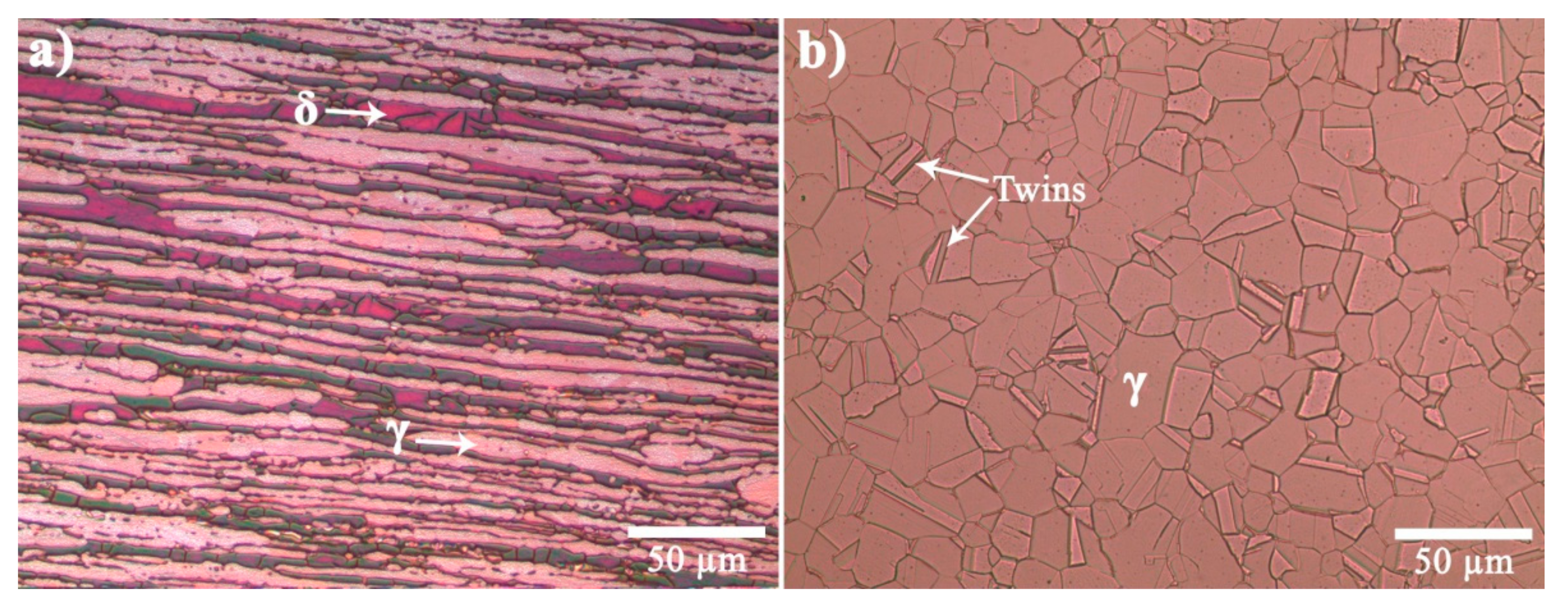
3.1. Microstructure of the Base Materials

Optical micrographs of the base materials in the rolling direction are shown in Figure 2. In Figure 2a the microstructure of the 2205 DSS consists of elongated grains of ferrite as the dark phase and austenite as the bright phase, with an approximate fraction of 46 and 54%, respectively. In Figure 2b, the microstructure of the 316L presents equiaxed grains of austenite with a grain size of 15.11 ± 5.73 μm. Moreover, it can be observed the twining produced by the applied mechanical shear forces during conformation of the 316L ASS into plates [35].

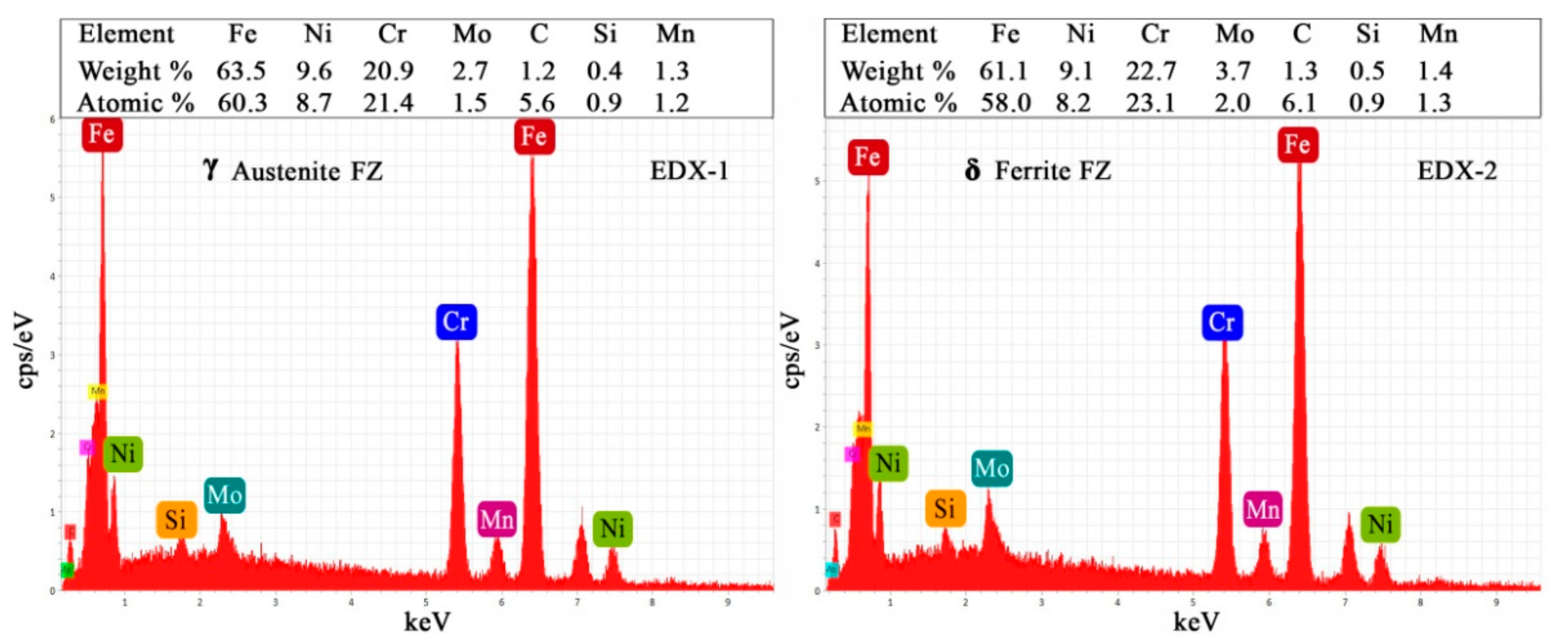
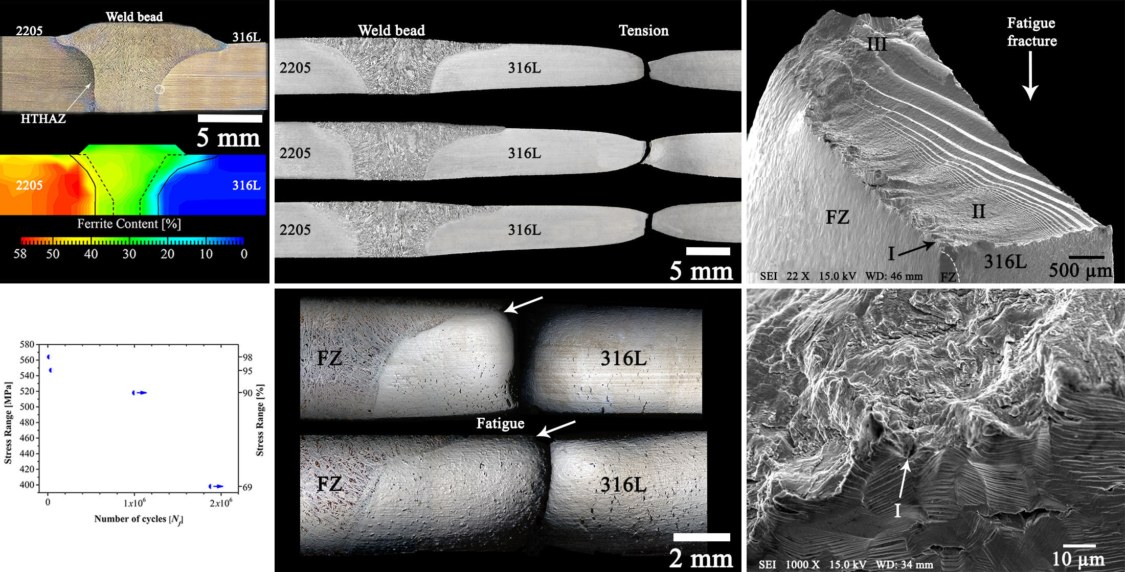
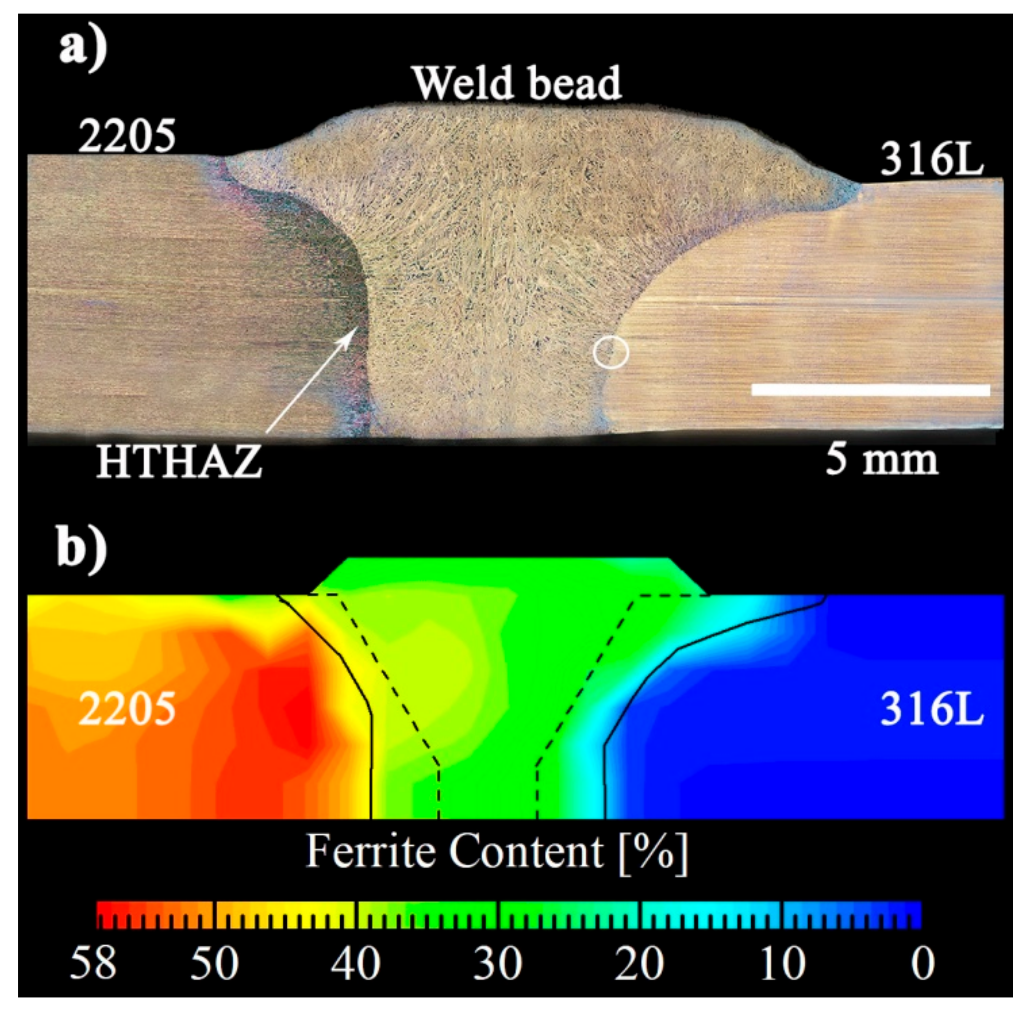
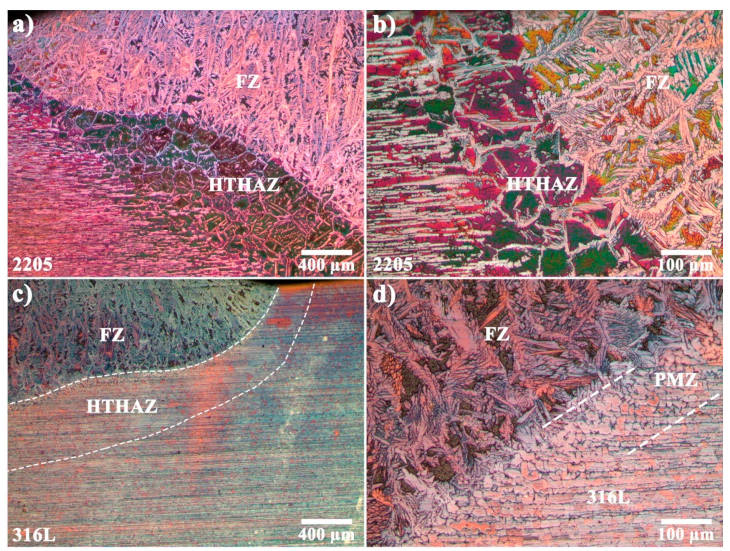
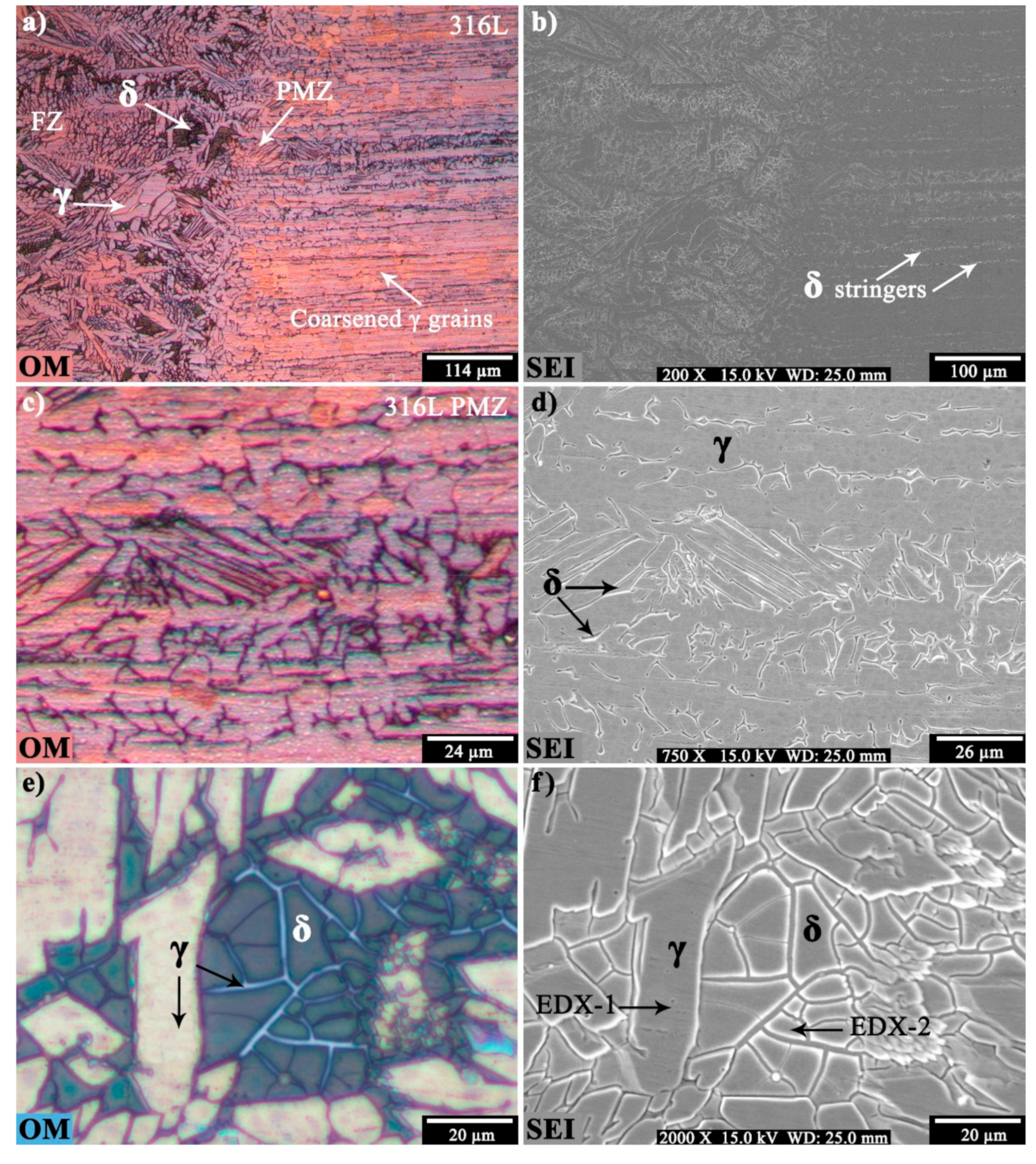
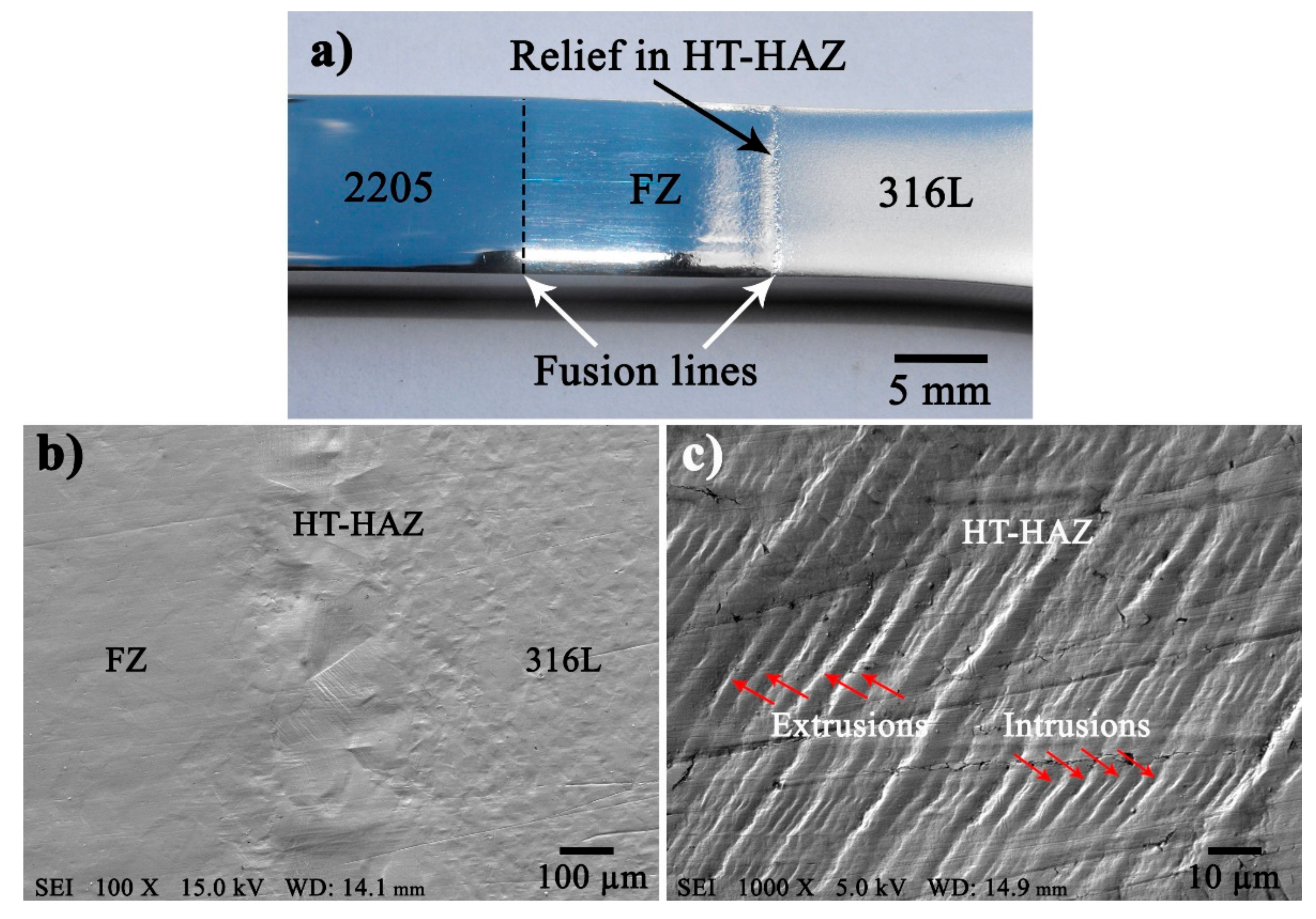
3.2. Macro and Microstructural Characteristics of the Welded Joint

Figure 3a shows a macro-view of the cross-section of the dissimilar welded joint obtained by assembling optical micrographs, the white circle shows the area analyzed by EDX in the SEM. The macrograph exhibits full penetration throughout the height in both sides of the plates without lack of lateral fusion, no macroporosity and neither cracks are visible to the naked eye. It is possible to observe clearly the morphology and the extension of the weld bead, the high temperature heat affected zone (HT-HAZ) and base materials. The geometrical cross-sectional area measurements and the calculation of the dilution ratios are given in Table 2. The 2205 DSS has lower thermal expansion and higher thermal conductivity coefficients than 316L ASS [12,36]. The dissimilar welded joint shows different dilution rates in each side due to the difference in thermophysical properties between base materials, being the dilution of the welded joint approximately 30.65%. The data shown in Table 2 indicates that the dilution of the 316L BM accounts for 66.66% of the total dilution of the welded joint. The estimated Creq/Nieq ratio of the fusion zone is 2.12 as calculated with the aid of the WRC-1992 diagram [30] for the total dilution rate. Figure 3b illustrates the variation in the content of ferrite across the width of the welded joint as measured with the ferritescope test. According to this map, the ferrite content in the 2205 BM varies between 46% to 58% whereas the 316L BM has about 1% ± 0.5%. A significant gradient can be seen from the HT-HAZ of the 2205 to the HAZ of the 316L ASS. This gradient is related to the chemical composition of the filler metal and to the levels of dilution in every side of the weld along with the chemical composition of each base metal. Thus, the map reveals that in the FZ there is more austenite in the side of the ASS than in the side of the DSS, this fact is even more accentuated along the fusion line where the content of austenite varies between 78% to 88%.
Figure 4 presents some details of the microstructure at the fusion line in both sides of the welded joint. The interface at the 2205 DSS side is shown in Figure 4a,b, it can be seen that the microstructure of the FZ consists of a continuous network of austenitic grains in the form of Widmanstätten plates embedded in a matrix of ferrite. Both, the 2205 DSS and the FZ obey the ferrite (F) mode of solidification (L → L+ δ→δ→δ + γ), where “L” is liquid, “δ” is delta ferrite and “γ” is austenite [30,37,38]. The weld metal solidifies from the partially melted coarse ferritic grains of the 2205 HT-HAZ. An estimation of the contents of phases at the center of the FZ by area fraction measurements drew approximately 33.5% ± 3.9% and 66.4% ± 3.9% of ferrite and austenite, respectively, in good agreement with the map of Figure 3b. The content of austenite in the FZ is abundant owing to the high content of gammagenous elements in the metallurgical design of the filler wire and the nitrogen in the shielding gas. It is a common practice to add nitrogen into the shielding gas to favor the formation of austenite and to compensate for possible losses of nitrogen during welding of DSS [39,40]. Due to these aspects, the approximate 50/50 balance between the two phases is not obtained in this zone.
In addition, Figure 4a,b also exhibit large ferritic grains delimiting the width of the 2205 HT-HAZ which extends up to ~1.28 mm. This zone corresponds to the region adjacent to the fusion line where the peak temperatures reached during welding virtually dissolved the pre-existing austenite in the 2205 BM and promoted grain growth in the ferritic matrix. During cooling, austenite began to form in the boundaries of the coarsened grains of ferrite along with Widmanstätten and some intragranular austenite. Partially transformed austenite is also present. The microstructure at the 2205 HT-HAZ is a serious concern in terms of corrosion resistance and also it changes the mechanical properties as compared with the microstructure of the as-received 2205 plates [41,42].
In the counterpart, Figure 4c,d correspond to the side of the welded joint where failure initiation took place in fatigue testing. In Figure 4c partial coarsening of the austenitic grains mark the limits of the HT-HAZ to approximately 0.73 mm whereas in Figure 4d a partially melted zone (PMZ) is clearly appreciated as part of the HT-HAZ of the 316L base material. The latter zone is characterized by the presence of δ-ferrite formed at the grain boundaries because of partial melting and austenite transforming into ferrite. During rapid heating of the base materials, the grain boundaries generally melt at lower temperatures than the bulk because there are higher concentration of alloying elements and impurities. If the grain boundaries are enriched with ferrite former elements or are low in gammagenous elements, the rapid cooling rates prevent the ferrite–austenite transformation so that some ferrite is retained at room temperature. Thus, the vermicular pattern of ferrite is formed in the grain boundaries in the PMZ of the 316L ASS during the welding thermal cycle. The optical micrograph also reveals plenty of ferrite stringers aligned along the rolling direction, resulting from the segregation of ferritizer elements like Cr and Mo. Ferrite is rich in these elements and might induce the formation of Cr-rich brittle phases and depleted zones providing favorable sites for pitting and uniform corrosion when the steel is exposed to corrosive environments [7,43,44,45]. Regarding the FZ in this side of the weld, the microstructure is somehow different to the 2205/2209 interface. This is readily explained by considering the dilution rates at each side of the weld, the calculated Creq/Nieq ratios are 2.5 and 2.05 for the 2205/2209 and 2209/316L interfaces, respectively. The partially melted grains of austenite act as substrates for nucleation and growth of ferrite during freezing of the weld pool. According to the WRC-1992 diagram and due to the Creq/Nieq ratio, precipitation of austenite occurs immediately and restricts the coarse columnar growth in the vicinity of the 316L/2209 interface. Approximately 200 μm beyond the fusion line, columnar grain growth prevails toward the heat source. Moreover, Figure 4d shows grains of austenite nucleating and growing from the partially melted grains of the 316L BM suggesting that local variations in the composition of the melt close to the fusion line enable competitive growth between ferrite and austenite due to uneven mixture between the molten filler and base material dragged into the weld pool. These microstructural observations correlate very well with the ferrite map of Figure 3b.
Optical microscopy and secondary electron (SE) mode imaging in the SEM along with EDX punctual analyses were performed to characterize, in detail, the microstructural features of the FZ and PMZ near the fusion line in the side of the 316L ASS as shown in Figure 5. Figure 5a,b exhibit the precipitation of δ-ferrite stringers and the grain growth of the austenitic matrix mainly occurring at the mid-height of the 316L plates. According to Table 2, even with the low content of Nb and C in the 316L stainless steel, thermodynamics suggests the presence of niobium carbides which might explain the limited grain growth in the HAZ of the 316L BM. The micrographs of Figure 5c,d present vermicular ferrite at the 316L PMZ along with δ stringers whereas Figure 5e,f show in detail the ferritic matrix crowded by austenite. The EDX punctual chemical analyses shown in Figure 6 correspond to the arrows and labels indicated in the SE image of Figure 5f.
The ferrite of the FZ is richer in Mo and Cr as compared to austenite which is characterized by the larger content of Fe and Ni according to the semi-quantitative analyses of the EDX spectra. Most filler metals for duplex alloys have relatively high Mo contents, to assure the corrosion resistance of the weld metal, but it results in different segregation degrees of Mo, increasing the tendency to form detrimental intermetallic phases [46,47].

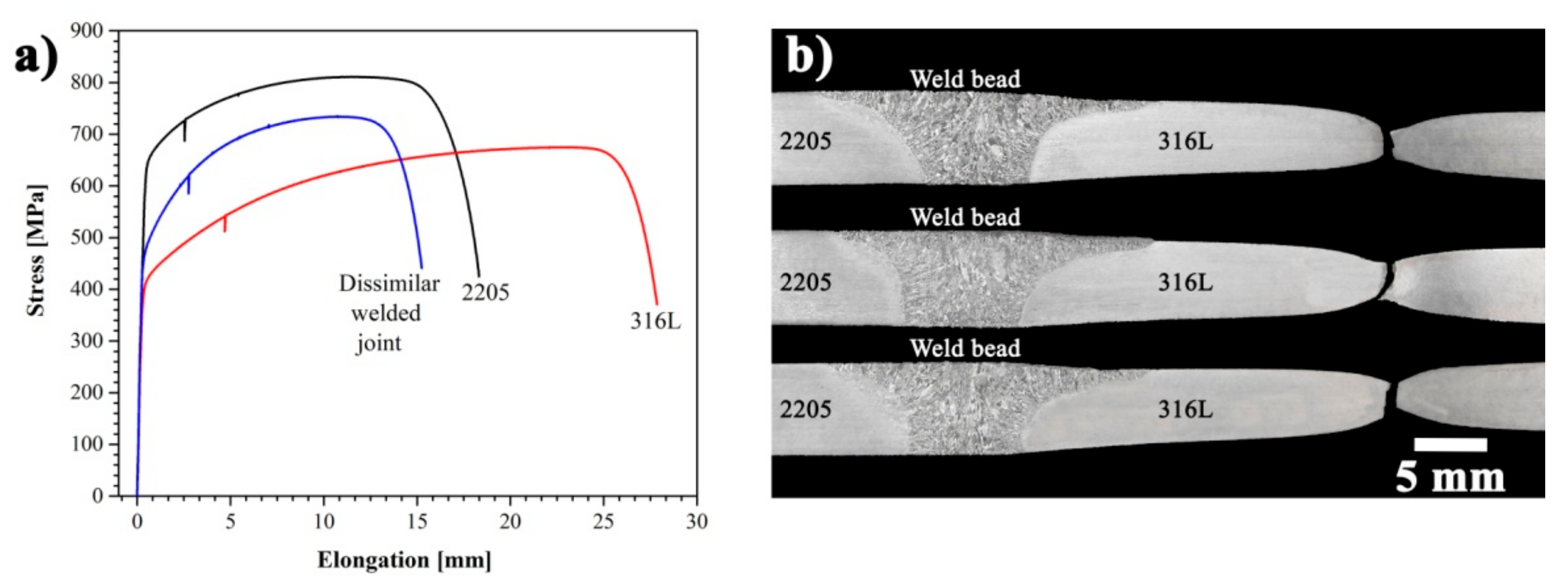
3.3. Mechanical Strength of the Welded Joint under Tension

Figure 7a shows the representative stress-strain curves of the tensile tests of base materials 2205 and 316L in the rolling directions in the as-received condition and the curve of the welded joint. The results of these tests are reported in Table 3 and were used to set the parameters of the fatigue tests. The stress–strain behavior of the welded specimens was highly consistent, indicating a sound welded joint. Accordingly, Figure 7b shows the failure zone of the tensile specimens of the welded joints. The failure mode was ductile and occurred on the side of the 316L BM, away from the FZ and beyond the HAZ. The 2205 DSS and the welded joint had higher mechanical strength, while the 316L ASS presented a significantly higher toughness. The tensile strength and the yield stress of the dissimilar welded joint were higher than the value of the as-received 316L ASS, showing an increase of approximately 61 and 59 MPa, respectively. This represents a moderate increment of ~9% in the ultimate tensile strength. There was also a notable reduction in ductility of the welded samples, with an elongation close to that of the 2205 DSS. The precipitation of ferrite bands as a result of the welding thermal cycle occurred throughout the thickness, but mainly in the mid height at the HAZ of the 316L plate increasing the mechanical strength to some extent. This increment is because the ferrite–austenite interphase boundaries are stronger barriers to dislocation movement in comparison to austenite–austenite grain boundaries [48,49,50].

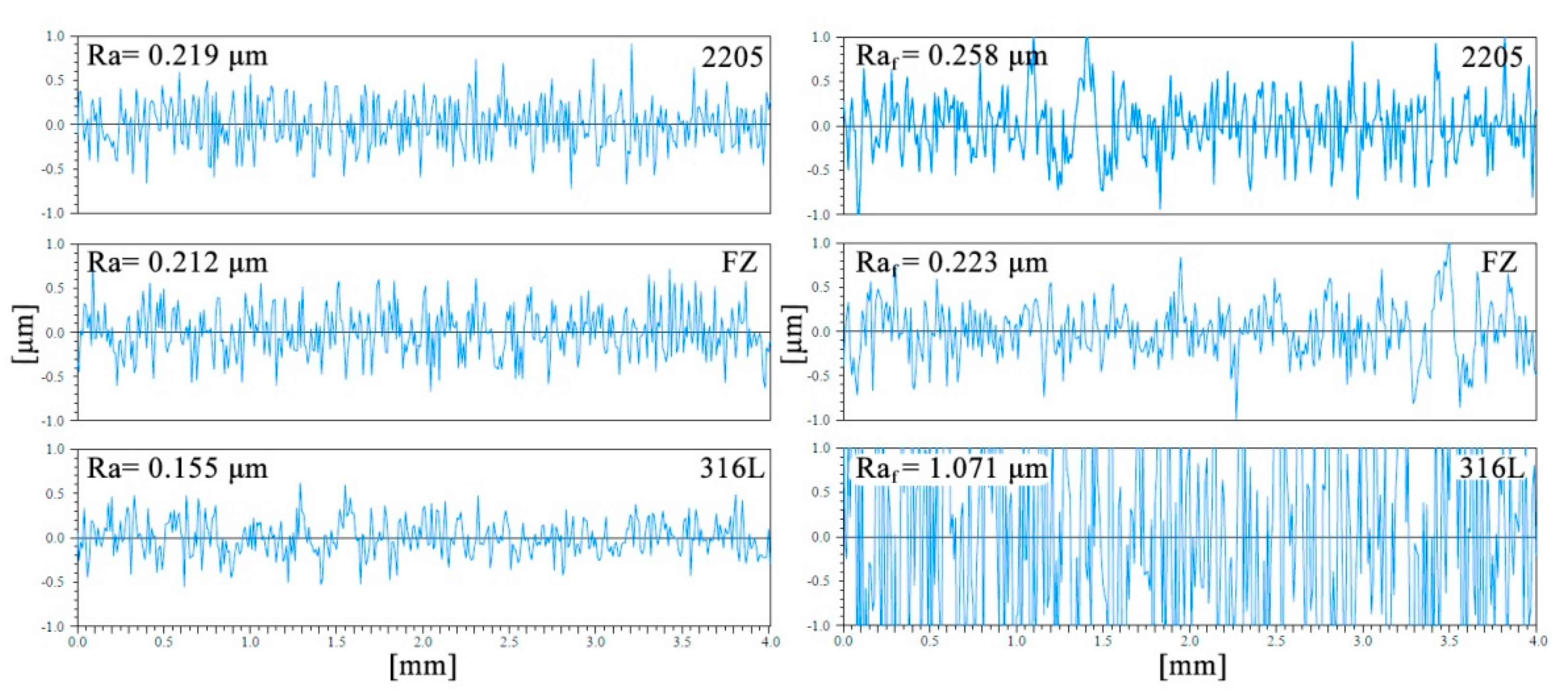
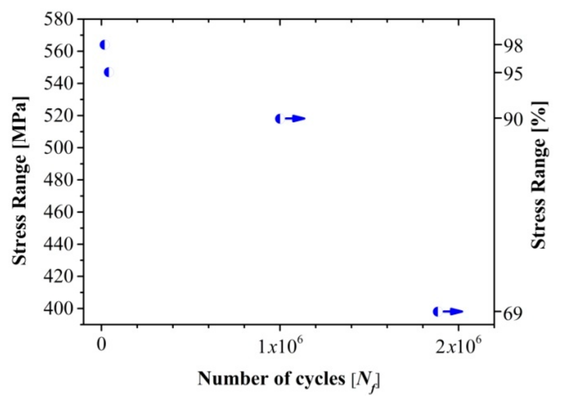
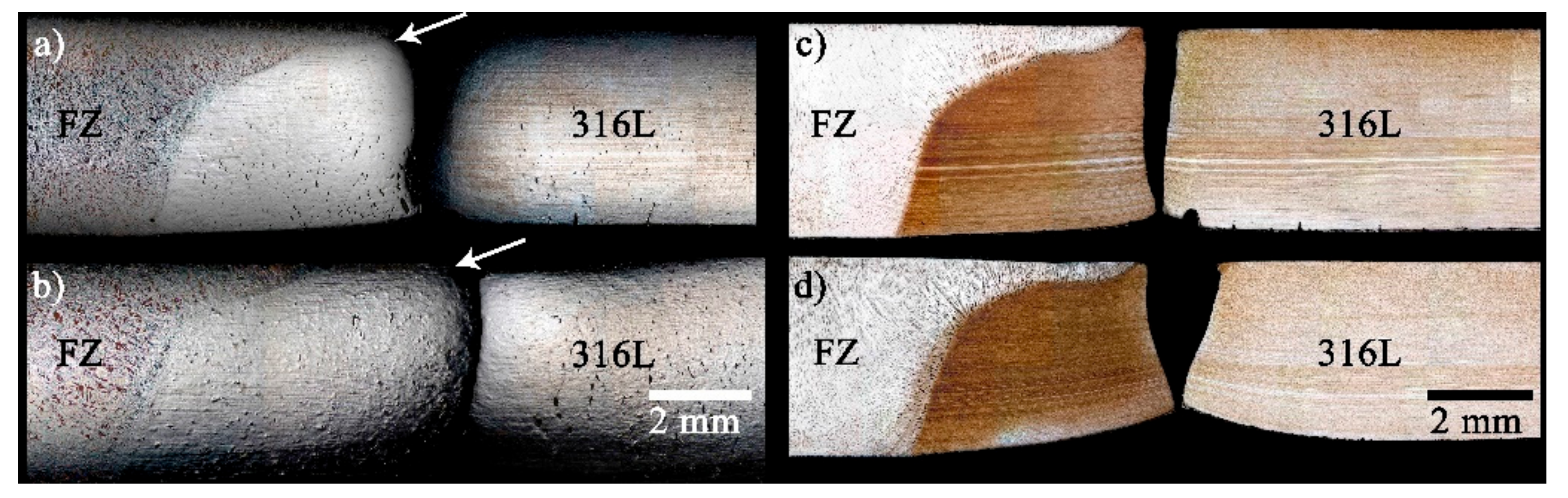
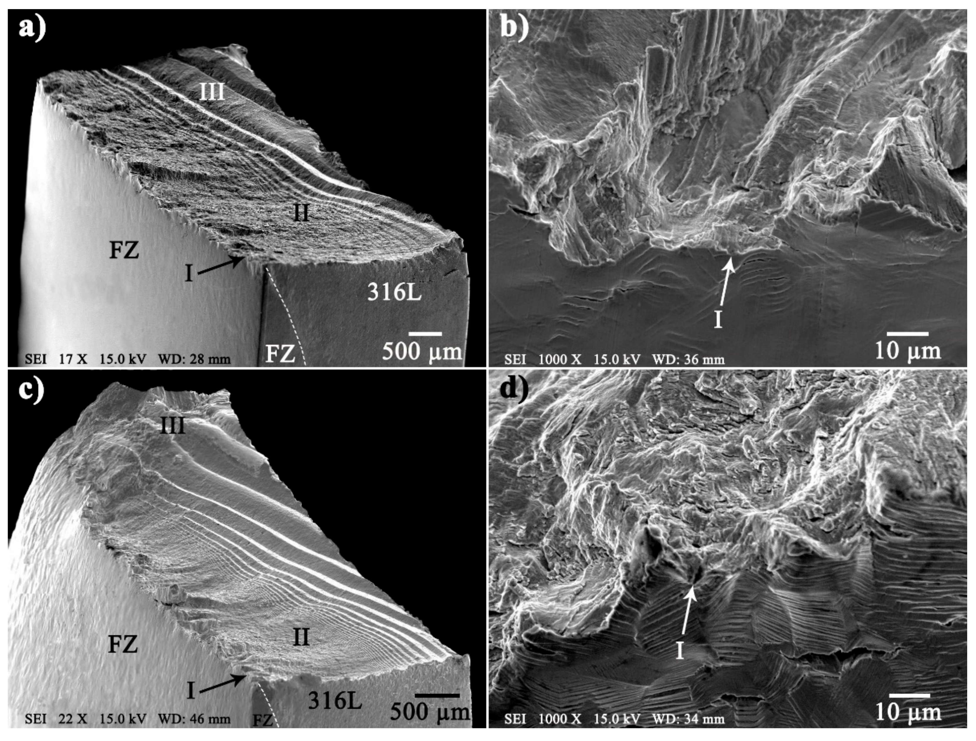
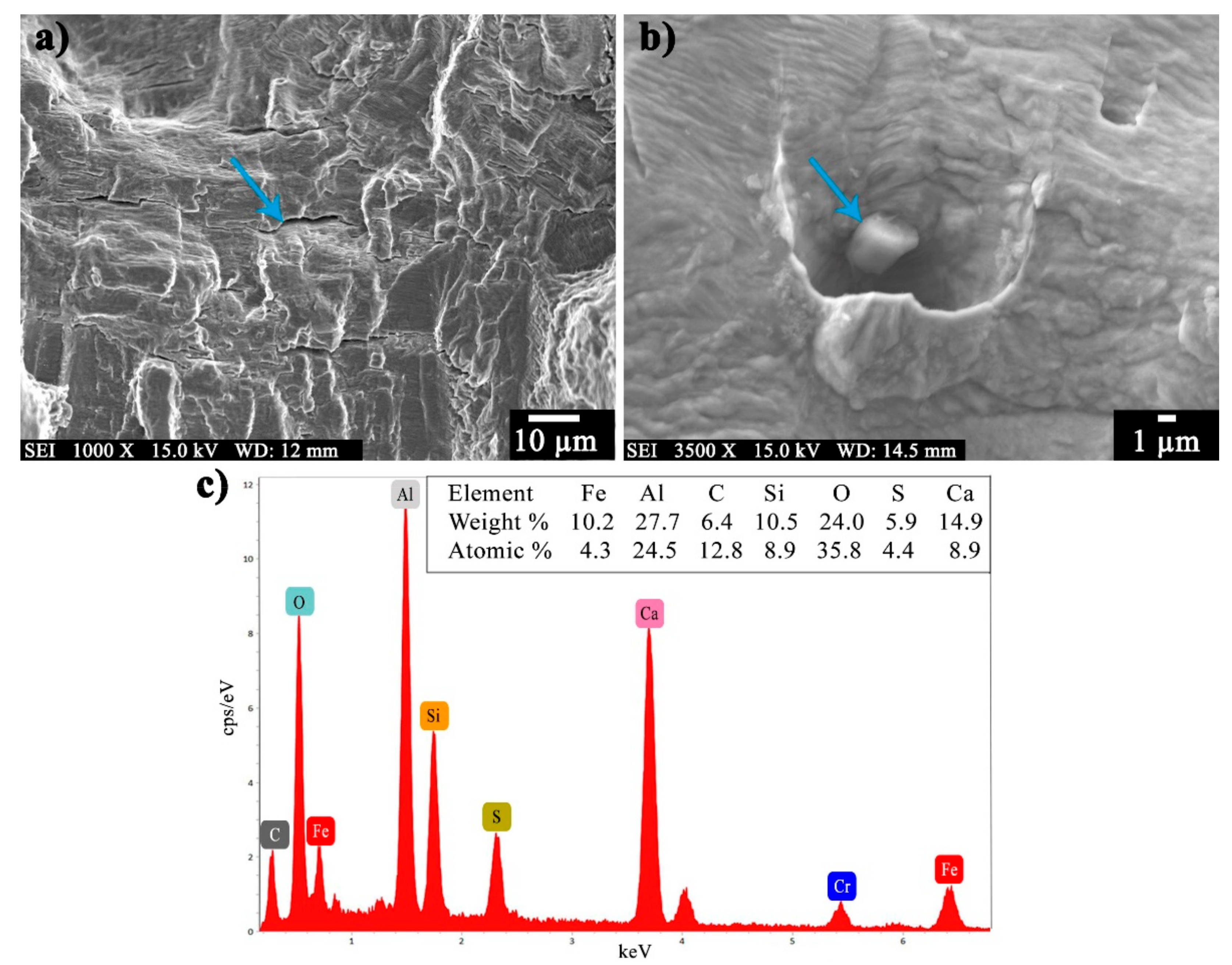
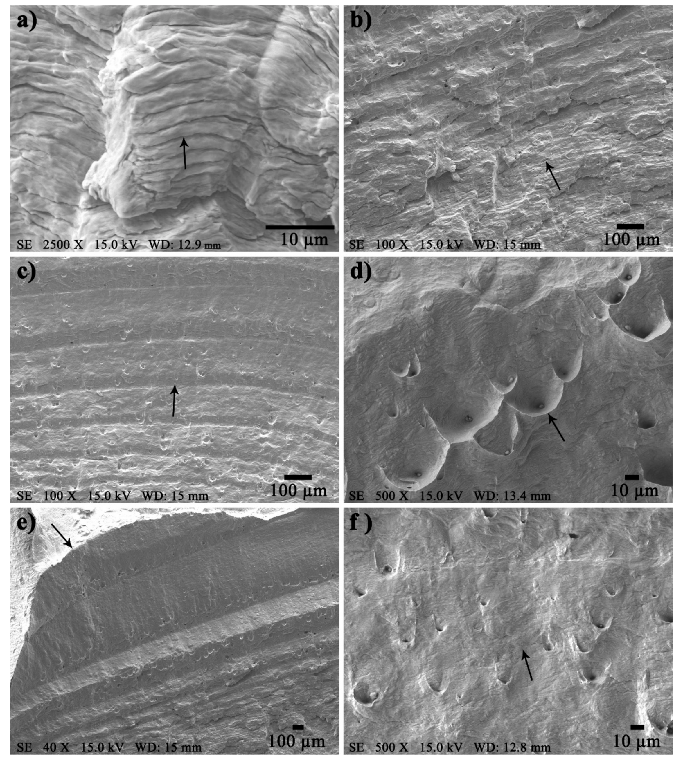
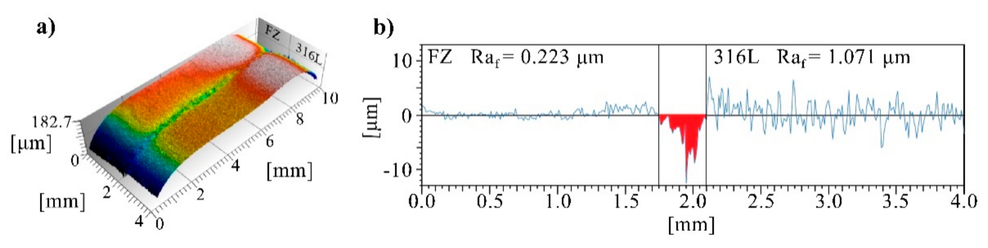
3.4. Fatigue Behavior

From the results of the mechanical properties under tension of the dissimilar welded joint, the parameters of the fatigue test were calculated and are given in Table 4. The highest stress range was 98% of the value of the maximum yield stress of the dissimilar welded joint, σy = 443 MPa, according to Table 3, this stress is slightly above the value of the as-received 316L BM. The results of the fatigue tests are plotted in Figure 8. The stress range (Δσ) must be at least 95% for the fatigue specimens to fail without reaching 106 cycles. Specimen three did not fail for 90% of the Δσ, reaching 106 cycles, likewise, the dissimilar welded joint did not fail at 68% of the Δσ, reaching up to 1,884,110 cycles.
It is known that ASSs can begin to deform upon 40% of the yield strength [13]. In general, the mechanical behavior of less than half the yield strength is considered totally elastic, and the plastic deformation is considered insignificant when the applied stress is below two-thirds of the yield strength. This quasi-elastic behavior is a consequence of the 12 sliding systems of austenite with a face-centered cubic (fcc) structure, that is very tough and ductile even at low temperature [13]. Due to the quasi-elastic behavior of the 316L ASS, a large Δσ needs to be applied generating crack initiation sites and leading to rapid rupture at low number of cycles, less than 106 [51].
In the fatigue tests, the cracks consistently initiated at the surface of the 316L base metal as shown in the macrographs of Figure 9. The images of Figure 9a,b were obtained after electropolishing and Behara’s tint etching whilst for Figure 9c,d the samples were mounted in epoxy resin, ground, polished and, finally, etched with Behara’s reagent. For both stress ranges, the failure crack nucleated very close to the weld toe, as pointed by the arrows in Figure 9a,b, and then propagated through the thickness of the 316L. The fatigue crack propagation in ASSs is favored mainly along {111} planes until it arrives at an adjacent grain of distinct crystallographic orientation. The crack is then forced to change its propagation direction to a favorably oriented plane [52]. The etching of the samples in the macrographs in the left side of Figure 9 preserved the damage suffered on the surface by the specimens during fatigue testing. The accumulation of damage observed in the broken specimens suggests that some level of hardening was induced by the welding thermal cycle in the HAZ of the 316L alloy as the right side of the fatigued samples exhibit more damage beyond certain distance from the fracture. Besides, it is evident the reinforcement provided by the toe of the weld bead as seen by the greater deformation experienced in the side of the root and the increase in the signs of damage from top to bottom. Nevertheless, critical fatigue cracks in welded joints usually occur at the weld toe where the thermal affection gives rise to coarsening of the grains and residual stresses which are maximized with respect to the rest of the welded joint owing to expansion-contraction effects along with phase transformations at high temperature. In this instance, the PMZ of the 316L is likely to predispose the favorable site for cracks nucleation. Fatigue cracks may be readily produced in this region where the residual stress transverse to the weld toe is typically positive and might approach the yield stress [53].
Figure 10a,c show the overall view of the fractured specimens under fatigue. In these images, the fractured surfaces exhibit the characteristic mixed-mode of fracture for fatigued specimens with flat and slant relieves. Figure 10b,d show the edges of the fractures and polished surfaces of the specimens tested. The short river patterns of the fractured surface exhibit the location where the cracks nucleated at sites of high-stress concentration. The black arrows indicate the nucleation site of the crack and the crack propagation direction follows the three distinctive stages; I, II and III. In stage I, the initiation of the failure begins with nucleation of the crack on the surface of the specimen at sites of high-stress concentration, characterized by fragile fracture due to the mechanism of cleavage or transgranular fracture along crystallographic planes. This may occur in fcc alloys when subjected to severe conditions like extremely high strain rates or very low temperatures [54].
Notice the effect of the 3% difference in stress range by the higher density, Figure 10d, of parallel microcracks in the individual grains of the 316L alloy for the 98% stress range specimen as compared to the 95% (Figure 10b). The significant level of damage observed in Figure 9a,b and Figure 10b,d correlates very well with the Nf cycles to failure registered during fatigue testing of the welded specimens.
Figure 11 shows details of the fracture surface of the 547 MPa stress range sample. In Figure 11a secondary microcracks are clearly distinguished whereas Figure 11b exhibits an inclusion pointed by the arrow. Figure 11c shows the EDX spectrum and chemical composition of the inclusion, which is composed mainly by Ca, Si, S and Al. It is obvious that this type of inclusions act as high-stress concentrators favoring the initiation and propagation of cracks during the cycle applied force. Bulk steel production involves deoxidation and inoculation by adding these elements, which act as multiple nucleation sites promoting grain refinement [36]. The content, size and even interconnectivity of these inclusions in stainless steels, might significantly reduce high-cycle fatigue strength by the nucleation of microcracks and their eventual coalescence [54,55]. In this study, however, the experimental evidence shows that these particles did not play a major role in dictating the fatigue life of the 2205/316L stainless steel dissimilar welded joint.
In stage II, the propagation front of the crack in a brittle mode varies with the stress range, as a result of each loading cycle. For instance, in Figure 12a, the spaces between striations taken at a distance about 566 μm from the crack initiation are 2.39 ± 0.44 μm, which commonly correspond to individual loading cycles. Figure 12b,c show the crack propagation in a pattern of beach marks characteristic of crack growth due to fatigue fracture at different periods. The space between crack progression marks in Figure 12b is 11.78 ± 0.88 μm, whilst in Figure 12c at 2.8 mm from the crack initiation, the spacing is significantly larger, in the order of 142.20 ± 0.33 μm.
Stage III is the final failure characterized by regions of fast-fracture mode with evidence of oblique plastic deformation. In Figure 12d it can be observed a shear lip formed on the lateral surface at approximately 45° to the loading direction, as an indication of partially ductile fracture.
Fracture toughness depends on the material thickness; nonetheless, the characteristics of the fracture surfaces are both, plane stress and plane strain. From Figure 12d–f, it can be observed that striations do not appear because rapid failure prevails, but parabolic-shaped dimples appear at the surface of shear lip resulting from shear failure.
Fatigue cracks are initiated at heterogeneous nucleation sites due to different causes like preexistent flaws within the material, dense bands of highly localized slip generated during the cyclic straining process or weld imperfections such as incomplete fusion, porosity and slag inclusions. In addition, the residual stresses caused by thermal expansion during the welding process and its subsequent contraction during solidification, all may contribute to poor fatigue performance of welded joints [54,56,57,58].
Figure 13 and Figure 14 present details of the surface features of the unbroken fatigued specimen 4 where the stress range was relatively low, Δσ = 69%, giving the conditions so that slip bands were generated, and strain took place without nucleating any cracks that could induce failure. In the macrograph of Figure 13a, a relief is pointed along the top surface of the welded joint, between the weld toe and the 316L BM. The apparition of this crevice was typical during the fatigue essays, it appeared soon after certain number of cycles depending on the stress range.
The SEM images shown in Figure 13b,c show, in detail, topographic characteristics of the relief as seen by local elevations and depressions, as extrusions and intrusions, respectively, on the surface of the HT-HAZ of the 316L ASS. These features represent the first sign of fatigue damage which might lead to fatigue crack initiation in specimens under fatigue loading [59]. In polycrystalline metals and alloys, persistent slip bands generated during the cyclic straining process serve as fatigue crack nucleation sites. The intrusions are crack-like defects where fatigue cracks initiate [54,60]. A pronounced plastic deformation relief formed on the surface of 316L HT-HAZ with ~300 µm in width, 12.88 μm in depth and a volume of 0.05 mm3, as can be appreciated in detail in Figure 14.
Experimental evidence reveals that there is a large increase in average roughness after fatigue testing (Raf) of the 316L surface. Figure 15 shows roughness profiles of a fatigue specimen before and after testing. Notably, the 316L ASS exhibits the major increase in roughness, from Ra = 0.155 to Raf = 1.071 μm whereas the FZ and the 2205 BM did not change so significantly in surface roughness. Cracks nucleate at the surface of the 316L HT-HAZ and grow normal to the rolling direction, into the interior of the specimens.

4. Conclusions

This study investigated the fatigue life of the 2205/316L stainless steel dissimilar welded joint and based on the experimental results, the following conclusions are drawn:
The dissimilar welded joint experienced different dilution behavior at each BM due to differences in the thermophysical properties between DSS and ASS. The 316L plate contributed with 2/3 of the total dilution of the welded joint. The FZ in the side of the DSS obeyed the typical ferrite mode of solidification for these type of alloys followed by precipitation of austenite during cooling whereas in the side of the ASS, the dilution rate between the 2209 filler and the 316L ASS gave rise to a notably different microstructure. Growing of ferrite appears to compete with austenite along the fusion line, both nucleating from partially melted grains of the 316L base metal. The dilution rate and this mode of solidification significantly increased the content of austenite to values between 78% to 88% in this side of the FZ as corroborated with feritscope measurements.
The HAZ of the 316L ASS exhibited limited grain growth presumably owing to the presence of NbC particles. As a consequence of the welding thermal cycle, the HAZ was characterized by a band of partially melted grains with vermicular ferrite allocated in the grain boundaries and the content of ferrite increased in the BM due to precipitation of ferrite stringers. The favored diffusivity of Mo into this phase contributed to this microstructural alteration.
The failure of the welded joints under tensile stress consistently occurred in the 316L BM away from the FZ and HAZ with a strength moderately above (~9%) of the as-received 316L ASS. This is thought to be due to some hardening mechanism induced by the precipitation of more ferrite in the BM as ferrite–austenite interphases are stronger than austenite–austenite interphases, increasing thus strength and displacing away the zone susceptible to failure.
According to the S-N diagram for the 2205/316L stainless steel dissimilar welded joint, the tension-compression fatigue tests must be at least Δσ = 547 MPa to fail without reaching 106 cycles. Rupture of the welded joint under fatigue occurred also in the HAZ of the 316L BM and initiated very near to the weld toe.
Fractography in the SEM revealed typical flat and slant fracture surfaces with failure occurring in three stages. Surface characterization of the fatigue specimen by SEM and profilometry before and after testing, at a stress range of 398 MPa, revealed a significant increased in surface roughness of the 316L BM and the presence of multiple microcracks. The change in the texture of the surface was due to the formation of intrusions and extrusions. Surprisingly, in spite of the multiple microcracks seen, this specimen did not fail after 1,884,110 fatigue cycles.
Regarding the findings of this study, although a sound 2205/316L stainless steel dissimilar welded joint is obtained, care must be taken in not to demand more than 90% of the stress range under cyclic loading. If the fatigue life of the dissimilar welded joint is to be increased, the heat input must be decreased, either by modifying the joint design or by using a different transfer mode during welding. This would change the geometry of the weld bead and decrease residual stresses.

Author Contributions

S.L.H.-T. performed most of the experimental work and wrote the manuscript; V.H.L.-M. conceived the study, wrote and edited the manuscript; M.A.G.-R. aided in the mechanical evaluation, data analysis and discussion of the results; R.G.-H. supervised the welding process, microstructural characterization and reviewed the manuscript; A.R. assisted the fatigue tests, reviewed and discussed the manuscript, F.F.C.-L. carried out the welding process, supervised the fatigue tests and helped in editing the manuscript. All authors have read and agreed to the published version of the manuscript.

Funding

Coordinación de la Investigación Científica of the UMSNH.

Informed Consent Statement

Not applicable.

Data Availability Statement

The data presented in this study are available on request from the corresponding author.

Acknowledgments

The authors are thankful with Francisco Solorio for his help in the SEM operation. S.L.H.-T. acknowledges CONACyT Mexico for the scholarship granted.

Conflicts of Interest

The authors declare no conflict of interest.

References

  1. Briones Flores, R.; Ruíz, A.; Rubio-González, C.; López, V.H.; Ortiz Lara, N.; Garcia Hernández, R.; Curiel López, F.F. Effect of heat input and accumulated fatigue damage on mechanical properties of dissimilar AL-6XN/316L welded joints. Mater. Character. 2016, 112, 41–50. [Google Scholar] [CrossRef]
  2. Verma, J.; Taiwade, R.V.; Khatirkar, R.K.; Kumar, A. A comparative study on the effect of electrode on microstructure and mechanical properties of dissimilar welds of 2205 austeno-ferritic and 316L austenitic stainless steel. Mater. Trans. 2016, 57, 494–500. [Google Scholar] [CrossRef] [Green Version]
  3. Verma, J.; Taiwade, R.V. Effect of welding processes and conditions on the microstructure, mechanical properties and corrosion resistance of duplex stainless steel weldments—A review. J. Manuf. Process. 2017, 25, 134–152. [Google Scholar] [CrossRef]
  4. Verma, J.; Taiwade, R.V. Effect of austenitic and austeno-ferritic electrodes on 2205 duplex and 316L austenitic stainless steel dissimilar welds. J. Mater. Eng. Perform. 2016, 25, 4706–4717. [Google Scholar] [CrossRef]
  5. Eghlimi, A.; Shamanian, M.; Eskandarian, M.; Zabolian, A.; Szpunar, J.A. Characterization of microstructure and texture across dissimilar super duplex/austenitic stainless steel weldment joint by austenitic filler metal. Mater. Character. 2015, 106, 208–217. [Google Scholar] [CrossRef]
  6. Jebaraj, A.V.; Kumar, T.S.; Manikandan, M. Investigation of structure property relationship of the dissimilar weld between austenitic stainless steel 316L and duplex stainless steel 2205. Trans. Indian Inst. Met. 2018, 71, 2593–2604. [Google Scholar] [CrossRef]
  7. Dokme, F.; Kulekci, M.; Esme, U. Microstructural and mechanical characterization of dissimilar metal welding of Inconel 625 and AISI 316L. Metals 2018, 8, 797. [Google Scholar] [CrossRef] [Green Version]
  8. Puchi-Cabrera, E.; Saya-Gamboa, R.; La Barbera-Sosa, J.; Staia, M.; Ignoto-Cardinale, V.; Berríos-Ortiz, J.; Mesmacque, G. Fatigue life of AISI 316L stainless steel welded joints, obtained by GMAW. Weld. Inter. 2009, 23, 778–788. [Google Scholar] [CrossRef]
  9. Huang, H.W.; Wang, Z.B.; Lu, J.; Lu, K. Fatigue behaviors of AISI 316L stainless steel with a gradient nanostructured surface layer. Acta Mater. 2015, 87, 150–160. [Google Scholar] [CrossRef]
  10. Plaut, R.L.; Herrera, C.; Escriba, D.M.; Rios, P.R.; Padilha, A.F. A short review on wrought austenitic stainless steels at high temperatures: Processing, microstructure, properties and performance. Mater. Res. 2007, 10, 453–460. [Google Scholar] [CrossRef]
  11. Mohammad, K.; Zainudin, E.; Salit, M.; Zahari, N.; Ali, A. Experimental determination of the fatigue behavior of austenitic 316L stainless steel under fatigue and creep-fatigue tests at high temperature. Inter. J. Met. Steel Res. Technol. 2013, 1, 1–11. [Google Scholar]
  12. Shields, J.; Kovach, C. Practical Guidelines for the Fabrication of High Performance Austenitic Stainless Steels; The International Molybdenum Association: London, UK, 2010; ISBN 978-1-907470-10-3. [Google Scholar]
  13. McGuire, M.F. Stainless Steels for Design Engineers; ASM International: Almere, Amsterdam, 2008; p. 304. [Google Scholar]
  14. Wasnik, D.; Dey, G.; Kain, V.; Samajdar, I. Precipitation stages in a 316L austenitic stainless steel. Scripta Mater. 2003, 49, 135–141. [Google Scholar] [CrossRef]
  15. Lewis, M.H.; Hattersley, B. Precipitation of M23C6 in austenitic steels. Acta Metall. 1965, 13, 1159–1168. [Google Scholar] [CrossRef]
  16. Terao, N.; Sasmal, B. Precipitation of M23C6 type carbide on twin boundaries in austenitic stainless steels. Metallography 1980, 13, 117–133. [Google Scholar] [CrossRef]
  17. U.S. Geological Survey. Metal Prices in the United States through 2010; 2012–5188; U.S. Geological Survey: Reston, VA, USA, 2013; pp. 105–113.
  18. Bursen, H. Winemaking equipment maintenance and troubleshooting. In Winemaking Problems Solved, 1st ed.; Butzke, C.E., Ed.; Woohead Publishing Limited: Cambridge, UK, 2010; pp. 199–253. [Google Scholar]
  19. Al-Haidary, J.; Wahab, A.; Salam, E.A. Fatigue crack propagation in austenitic stainless steel weldments. Metall. Mater. Trans. A 2006, 37, 3205–3214. [Google Scholar] [CrossRef]
  20. Sherry, A.; Wilkes, M. Numerical simulation of tearing–fatigue interactions in 316L (N) austenitic stainless steel. Inter. J. Press. Vess. Pip. 2005, 82, 905–916. [Google Scholar] [CrossRef]
  21. Mohammad, K.A.; Zainudin, E.S.; Sapuan, S.; Zahari, N.I.; Aidy, A. Fatigue life for type 316L stainless steel under cyclic loading. In Proceedings of Advanced Materials Research; Trans Tech Publications Ltd.: Zürich, Switzerland, 2013; pp. 77–81. [Google Scholar]
  22. Mohammad, K.; Ali, A.; Sahari, B.; Abdullah, S. Fatigue behavior of austenitic type 316L stainless steel. In Proceedings of IOP Conference Series: Materials Science and Engineering; IOP Publishing: Bristol, UK, 2012; p. 012012. [Google Scholar]
  23. Kumar, R.; Bhattacharya, A.; Bera, T.K. Mechanical and metallurgical studies in double shielded GMAW of dissimilar stainless steels. Mater. Manuf. Process. 2015, 30, 1146–1153. [Google Scholar] [CrossRef]
  24. Mohammed, G.R.; Ishak, M.; Aqida, S.N.; Abdulhadi, H.A. Effects of heat input on microstructure, corrosion and mechanical characteristics of welded austenitic and duplex stainless steels: A review. Metals 2017, 7, 39. [Google Scholar] [CrossRef] [Green Version]
  25. Silva Leite, C.G.; da Cruz Junior, E.J.; Lago, M.; Zambon, A.; Calliari, I.; Ventrella, V.A. Nd: YAG pulsed laser dissimilar welding of UNS S32750 duplex with 316L austenitic stainless steel. Materials 2019, 12, 2906. [Google Scholar] [CrossRef] [Green Version]
  26. Landowski, M.; Świerczyńska, A.; Rogalski, G.; Fydrych, D. Autogenous fiber laser welding of 316L austenitic and 2304 lean duplex stainless steels. Materials 2020, 13, 2930. [Google Scholar] [CrossRef]
  27. Man, J.; Obrtlik, K.; Polak, J.; Klapetek, P. Early stages of fatigue damage in 316L steel. In Proceedings of the Fracture of Nano and Engineering Materials and Structures, Alexandroupolis, Greece, 3–7 July 2006; pp. 871–872. [Google Scholar]
  28. Chiu, P.; Wang, S.; Yang, J.; Weng, K.; Fang, J. The effect of strain ratio on morphology of dislocation in low cycle fatigued SAF 2205 DSS. Mater. Chem. Phys. 2006, 98, 103–110. [Google Scholar] [CrossRef]
  29. Man, J.; Obrtlík, K.; Polák, J. Extrusions and intrusions in fatigued metals. Part 1. State of the art and history. Philosoph. Mag. 2009, 89, 1295–1336. [Google Scholar] [CrossRef]
  30. Kotecki, D.; Siewert, T. WRC-1992 constitution diagram for stainless steel weld metals: A modification of the WRC-1988 diagram. Weld. J. 1992, 71, 171–178. [Google Scholar]
  31. Bosworth, M. Effective heat input in pulsed current gas metal arc welding-solid wire electrodes. Weld. J. 1990, 70, 111-s. [Google Scholar]
  32. Vander Voort, G.F. Metallography, Principles and Practice; ASM International: Almere, The Netherlands, 1984. [Google Scholar]
  33. ASTM. E8-04, Standard Test Methods for Tension Testing of Metallic Materials. In Annual Book of ASTM Standards; ASTM: West Conshohocken, PA, USA, 2004; p. 3. [Google Scholar]
  34. Designation, A. E466-07, Standard Practice for Conducting Force Controlled Constant Amplitude Axial Fatigue Tests of Metallic Materials; ASTM International: West Conshohocken, PA, USA, 2007. [Google Scholar]
  35. Song, R.-B.; Xiang, J.-Y.; Hou, D.-P. Characteristics of mechanical properties and microstructure for 316L austenitic stainless steel. J. Iron Steel Res. Inter. 2011, 18, 53–59. [Google Scholar] [CrossRef]
  36. Gunn, R.N. Duplex Stainless Steels: Microstructure, Properties and Applications; Woodhead Publishing: Cambridge, UK, 1997. [Google Scholar]
  37. Elmer, J.; Allen, S.; Eagar, T. Microstructural development during solidification of stainless steel alloys. MTA 1989, 20, 2117–2131. [Google Scholar] [CrossRef]
  38. Saluja, R.; Moeed, K. The emphasis of phase transformations and alloying constituents on hot cracking susceptibility of type 304L and 316L stainless steel welds. Inter. J. Eng. Sci. Technol. 2012, 4, 2206–2216. [Google Scholar]
  39. Sathiya, P.; Aravindan, S.; Soundararajan, R.; Haq, A.N. Effect of shielding gases on mechanical and metallurgical properties of duplex stainless-steel welds. J. Mater. Sci. 2009, 44, 114–121. [Google Scholar] [CrossRef]
  40. Bermejo, M.V.; Karlsson, L.; Svensson, L.-E.; Hurtig, K.; Rasmuson, H.; Frodigh, M.; Bengtsson, P. Effect of shielding gas on welding performance and properties of duplex and superduplex stainless steel welds. Weld. World 2015, 59, 239–249. [Google Scholar] [CrossRef]
  41. Xavier, C.R.; Delgado Junior, H.G.; Castro, J.A.d. An experimental and numerical approach for the welding effects on the duplex stainless steel microstructure. Mater. Res. 2015, 18, 489–502. [Google Scholar] [CrossRef] [Green Version]
  42. Badji, R.; Bouabdallah, M.; Bacroix, B.; Kahloun, C.; Belkessa, B.; Maza, H. Phase transformation and mechanical behavior in annealed 2205 duplex stainless steel welds. Mater. Character. 2008, 59, 447–453. [Google Scholar] [CrossRef]
  43. Kožuh, S.; Gojić, M.; Vrsalović, L.; Ivković, B. Corrosion failure and microstructure analysis of AISI 316L stainless steels for ship pipeline before and after welding. Kovove Mater. 2013, 51, 53–61. [Google Scholar]
  44. Mohammed, R.; Rao, K.S.; Reddy, G.M. Studies on microstructure, mechanical and pitting corrosion behaviour of similar and dissimilar stainless steel gas tungsten arc welds. In Proceedings of IOP Conference Series: Materials Science and Engineering; IOP Publishing: Bristol, UK, 2018; p. 012028. [Google Scholar]
  45. Dadfar, M.; Fathi, M.; Karimzadeh, F.; Dadfar, M.; Saatchi, A. Effect of TIG welding on corrosion behavior of 316L stainless steel. Mater. Lett. 2007, 61, 2343–2346. [Google Scholar] [CrossRef]
  46. Potgieter, J.; Olubambi, P.; Cornish, L.; Machio, C.; Sherif, E.-S.M. Influence of nickel additions on the corrosion behaviour of low nitrogen 22% Cr series duplex stainless steels. Corros. Sci. 2008, 50, 2572–2579. [Google Scholar] [CrossRef]
  47. Hao, Y.; Li, J.; Li, X.; Liu, W.; Cao, G.; Li, C.; Liu, Z. Influences of cooling rates on solidification and segregation characteristics of Fe-Cr-Ni-Mo-N super austenitic stainless steel. J. Mater. Process. Technol. 2020, 275, 116326. [Google Scholar] [CrossRef]
  48. Astaf’ev, A.A.; Lepekhina, L.I.; Batieva, N.M. Effect of delta-ferrite on the properties of welded joints of steel 08Kh18N10T. Met. Sci. Heat. Treat. 1989, 31, 880–884. [Google Scholar] [CrossRef]
  49. Nitronic, M.L.J. Regression analysis of the influence of a chemical composition on the mechanical properties of the steel nitronic 60. Mater. Tehnol. 2014, 48, 433–437. [Google Scholar]
  50. Almaida, G.; Mirsada, O.; Sulejman, M. Effect of the delta-ferrite content on the tensile proferties in nitronic 60 steel at room temperature and 750. Mater. Technol. 2012, 46, 519–523. [Google Scholar]
  51. Huang, J.-Y.; Yeh, J.-J.; Jeng, S.-L.; Chen, C.-Y.; Kuo, R.-C. High-cycle fatigue behavior of type 316L stainless steel. Mater. Trans. 2006, 47, 409–417. [Google Scholar] [CrossRef] [Green Version]
  52. Kusko, C.; Dupont, J.; Marder, A. The influence of microstructure on fatigue crack propagation behavior of stainless steel welds. Weld. J. 2004, 83, 6–14. [Google Scholar]
  53. Campbell, F.C. Fatigue and Fracture: Understanding the Basics; ASM International: Almere, Amsterdam, 2012. [Google Scholar]
  54. Hertzberg, R.W. Deformation and Fracture Mechanics of Engineering Materials; John Wiley Sons Inc.: Hoboken, NJ, USA, 1989. [Google Scholar]
  55. Marshall, P. Austenitic Stainless Steels: Microstructure and Mechanical Properties; Springer Science & Business Media: Berlin/Heidelberg, Germany, 1984. [Google Scholar]
  56. Macdonald, K. Fracture and Fatigue of Welded Joints and Structures; Elsevier: Amsterdam, The Netherlands, 2011. [Google Scholar]
  57. Zhao, X.H.; Liu, Y. Modification of plasma spurt spraying on improving fatigue property of welded joint. In Proceedings of Applied Mechanics and Materials; Trans Tech Publications Ltd.: Zürich, Switzerland; pp. 494–497.
  58. Lefebvre, F.; Peyrac, C.; Elbel, G.; Revilla-Gomez, C.; Verdu, C.; Buffière, J.-Y. Understanding of fatigue strength improvement of steel structures by hammer peening treatment. Proc. Eng. 2015, 133, 454–464. [Google Scholar] [CrossRef] [Green Version]
  59. Man, J.; Valtr, M.; Weidner, A.; Petrenec, M.; Obrtlík, K.; Polák, J. AFM study of surface relief evolution in 316L steel fatigued at low and high temperatures. Proc. Eng. 2010, 2, 1625–1633. [Google Scholar] [CrossRef] [Green Version]
  60. Cortés-Cervantes, I.S.; López-Morelos, V.H.; Miyashita, Y.; García-Hernández, R.; Ruiz-Marines, A.; Garcia-Renteria, M.A. Fatigue resistance of AL6XN super-austenitic stainless steel welded with electromagnetic interaction of low intensity during GMAW. Inter. J. Adv. Manuf. Technol. 2018, 99, 2849–2862. [Google Scholar] [CrossRef]
Figure 1. (a) single-V groove joint design, (b) schematic representation of specimens machined from the dissimilar welded joint for metallurgical and mechanical characterization and (c) dimensions of fatigue specimens (mm).
Metals 11 00093 g001
Figure 2. Microstructure of the as-received base materials; (a) 2205 duplex stainless steel (DSS) and (b) 316L austenitic stainless steel (ASS).
Metals 11 00093 g002
Figure 3. (a) transverse profile of the 2205/316L stainless steel dissimilar welded joint and (b) mapping of the ferrite content across the welded joint.
Metals 11 00093 g003
Figure 4. Microstructural characteristics of the weld at the fusion line; (a,b) side of the 2205 DSS and (c,d) side of the 316L ASS.
Metals 11 00093 g004
Figure 5. Details of the microstructure as seen in the optical microscope (OM) and the SEM at the side of the 316L ASS. (a,b) 2209/316L interface, (c,d) PMZ of the 316L and (e,f) weld metal.
Metals 11 00093 g005
Figure 6. Elemental EDX spectrums and compositions of ferrite and austenite at the weld metal as indicated by the arrows in Figure 5f.
Metals 11 00093 g006
Figure 7. (a) conventional stress versus elongation curves of the base materials and dissimilar welded joint and (b) macrographs of the dissimilar welded joints after tensile testing.
Metals 11 00093 g007
Figure 8. S-N diagram of the 2205/316L stainless steel dissimilar welded joint.
Metals 11 00093 g008
Figure 9. Transverse profiles of fatigued specimens for (a,c) 95% and (b,d) 98% of Δσ.
Metals 11 00093 g009
Figure 10. General view of the fracture of fatigue specimens and site of fracture initiation; (a,b) 547 MPa (95%) and (c,d) 564 MPa (98%) stress range.
Metals 11 00093 g010
Figure 11. Details of the fracture of the 547 MPa stress range sample. (a) secondary microcracks, (b) microvoid and (c) EDX spectra and composition corresponding to the inclusion indicated by the arrow in (b).
Metals 11 00093 g011
Figure 12. Details of the fracture of the 547 MPa stress range sample; (a) fatigue striations, (b,c) beach patterns, (df) parabolic-shaped dimples and (e) set of shear lip.
Metals 11 00093 g012
Figure 13. Surface features of unbroken fatigued specimen; (a) macrograph of the fatigue specimen, (b) SEM view of the fusion line at the side of the 316L ASS and (c) surface detail at the HT-HAZ of the 316L ASS.
Metals 11 00093 g013
Figure 14. Surface features of unbroken fatigued specimen of the fusion line at the side of the 316L ASS, (a) three-dimensional view and (b) roughness profile, roughness after fatigue testing (Raf).
Metals 11 00093 g014
Figure 15. Roughness profile of unbroken specimen before and after fatigue testing, average surface roughness (Ra) and Raf, respectively.
Metals 11 00093 g015
Table 1. Chemical composition of the stainless steel plates and filler wire employed (wt.%) and Creq/Nieq ratio based on the WRC-1992 diagram [30].
MaterialCCrNiMoMnPSSiNCuNbFeCreqNieqCreq/Nieq
22050.0122.55.73.11.810.03----0.540.160.210.03Bal.25.609.302.75
316L0.0216.610.02.01.150.03----0.540.050.460.03Bal.18.7111.861.57
ER22090.01238.83.21.750.020.010.50.140.10.02Bal.26.2012.042.17
Table 2. Dilution ratios and area measurements of the partially melted zone (PMZ) and high temperature heat affected zones (HT-HAZs).
MaterialArea
(mm2)
Dilution
(%)
2205 melted8.1310.95
316L melted14.6319.70
Weld metal 74.2630.65
316L PMZ0.92----
2205 HT-HAZ6.77----
316L HT-HAZ5.05----
Table 3. Mechanical properties of the as-received stainless steel plates and welded joint.
MaterialYield Stress
(MPa)
Tensile
Strength
(MPa)
Elongation (%)HV100
2205 DSS64081138272
316L ASS38467455215
ER220956069026240
Welded joint44373531----
Table 4. Parameters and results of the fatigue tests of the 2205/316L dissimilar welded joint.
SpecimenΔσ
[%]
Tensionσmáx
[MPa]
Compression
σmin
[MPa]
Δσ
[MPa]
Nf
[Cycles]
Time
[h]
Surface Crack Initiation
198434−13056418,2460.33HT-HAZ 316L
295420−12654741,4000.76HT-HAZ 316L
390398−1195181,000,32018.5Without failure
469306−923981,884,11034.9Without failure
Publisher’s Note: MDPI stays neutral with regard to jurisdictional claims in published maps and institutional affiliations.

