Article

The Corrosion Resistance of Al Film on AZ31 Magnesium Alloys by Magnetron Sputtering

School of Mechatronics and Vehicle Engineering, Chongqing Jiaotong University, Chongqing 400074, China
*
Author to whom correspondence should be addressed.
Metals 2021, 11(10), 1522; https://doi.org/10.3390/met11101522
Submission received: 30 August 2021 / Revised: 21 September 2021 / Accepted: 23 September 2021 / Published: 25 September 2021

Abstract

:
Nano Al films were prepared on AZ31 magnesium alloy samples by DC magnetron sputtering. The effects of sputtering power on the microstructure and corrosion resistance of the Al film were investigated. The results show that the surface of aluminum film is dense and polycrystalline state, and it is oriented along the Al (111) crystal plane. The grain size of Al film first increases and then decreases with the increase of sputtering power. When the sputtering power exceeds 100 W, there is no insignificant effect on the orientation of the Al crystals and the corrosion current density of the samples with Al film are reduced by two orders of magnitude. The corrosion resistance of the magnesium alloy samples with the Al film magnetron sputtered varies with the sputtering power. Compared with low sputtering power, the Al film sputtered by high power has the most excellent corrosion resistance, but too high sputtering power will lead to micro cracks on the Al film, which will adversely affect the corrosion resistance.

Graphical Abstract

1. Introduction

As a structural material, magnesium alloy has attracted more and more attention from the industry because of its advantages of light weight, high specific strength, good electrical conductivity, good electromagnetic shielding performance, good biocompatibility and easy recycling. At present, the applications of magnesium alloy are mainly concentrated in the fields of automobiles, aerospace, electronic products and biomedicine [1,2,3,4,5]. Unfortunately, magnesium alloys have high chemical activity and are easily corroded even at room temperature, which limits the practical application of magnesium alloys [6,7].
In fact, metal corrosion is a chemical or electrochemical reaction on the metal surface that causes the metal atoms to lose electrons and turn into an ion. The corrosion product Mg(OH)2 and H2 are produced by electrochemical reaction of magnesium and water in aqueous solution [8]. The poor corrosion resistance of magnesium and its alloy is mainly due to two key factors: (1) The high negative potential of magnesium will lead to continuous corrosion even in an anoxic environment; (2) the surface film formed on magnesium is less protective [9]. This means that any oxide or hydroxide layer formed on the surface of magnesium is soluble in most water environments or humidity conditions. In addition, according to the Pilling–Bedworth principle, the PB (oxide/metal volume ratio) ratio of MgO/Mg is 0.81 < 1, and the spontaneous oxide film cannot completely cover and effectively protect the surface of the magnesium metal substrate [10].
To further expand the application of magnesium alloy, it is critical to solve the problem of poor corrosion resistance of magnesium alloys. In the past two decades, many achievements in improvement of corrosion resistance of magnesium alloys have been made by researchers and engineers. To further enhance the corrosion resistance of magnesium alloys, much research is mainly concentrated in two aspects: the improvement of the purity of magnesium alloys and the minimization of the content of heavy metal impurity in magnesium alloys and the development of surface treatment methods to protect the surface of magnesium alloy.
In recent years, the development of surface modification technology has been accelerated, and various coating technologies have been tried in the surface treatment of magnesium alloys, such as Chemical Conversion Treatment [11], Anodizing and Micro-arc Oxidation [12], Electrochemistry Plating [13], Thermal Spraying [14], Vapor Deposition [15,16], Laser Surface Treatment [17], Steam Coating Treatment [18], etc. Among various surface modification methods, Magnetron Sputtering, as a deposition method of Physical Vapor Deposition (PVD), is effective to prevent the corrosive medium from contacting the magnesium substrate. Magnetron Sputtering also has many advantages such as being environmentally friendly and low cost, its strong bonding force and its high deposition rate. Therefore, Magnetron Sputtering as a promising coating technology has been rapidly developed and wildly concerned. At present, the research on the surface modification of magnesium alloys by magnetron sputtering mainly focus on preparation of high-quality anti-corrosion films of different systems and optimization of the process parameters of Magnetron Sputtering to obtain high-quality films.
Zhang et al. [19] studied the influence of different sputtering time on the corrosion resistance of aluminum films, and found that when the sputtering time was increased from 120 to 150 min, the corrosion potential of the aluminum film increased slightly; when the sputtering time was extended to 300 min, the corrosion potential increased by 166 mV greater than that of the bare magnesium alloy, and the corrosion current density was also reduced by three orders of magnitude, which significantly improved the corrosion resistance of the magnesium alloy. Wu et al. [20] studied the effects of bias voltage on coating performance and found that increasing the bias voltage can make the surface structure of the chromium coating more compact, but under excessively high bias voltage, the corrosion potential of the chromium coating becomes lower. The result may be due to the poor bonding force between the coating and the substrate, and the high expansion rate of the corrosion pits. Generally speaking, the preparation of dense and stable coatings as a physical barrier can effectively inhibit the corrosion of magnesium substrates. However, in some environments, the coating will inevitably be damaged during use. In this case, the strong self-healing ability based on the strong self-repairing ability is very important to protect magnesium alloy. Al has a strong affinity with oxygen atoms and can spontaneously form a dense and stable aluminum oxide film on the surface of magnesium alloy. Therefore, the investigation on effects of different sputtering power on the microstructure and corrosion resistance of Al film on AZ31 magnesium alloy was carried out.

2. Materials and Methods

2.1. Materials

The AZ31 magnesium alloy sheet was cut into small blocks of 10 mm × 10 mm × 5 mm by electric discharge wire, which was used as the substrate for magnetron sputtering. Firstly, the AZ31 magnesium alloy substrate was polished using water-abrasive paper from 200# to 1500# until there are no obvious scratches and dirt on the surface of the samples; then, the small block of polished magnesium alloy were polished in a polishing machine until the surface was very smooth. Finally, the samples were ultrasonically cleaned with absolute ethanol for 10 min, then dried with cold air and placed in a vacuum chamber for later use.

2.2. Coating Preparation

The test uses VCX-450 high-vacuum Magnetron Sputtering Coating System (AutoVac, Co., Ltd., Shenyang, China) to prepare Al film. The pre-processed AZ31 magnesium alloy samples were put into the vacuum chamber, and the Al sputtering target with purity greater than 99.999% was used. The distance between the sputtering target and the substrate was adjusted to 60mm, then the background vacuum was pumped to 1 × 10⁻³ Pa, and a certain amount of high-purity (99.999%) argon with a flow rate of 30 sccm was passed in. Before depositing the Al film, pre-sputtering the target surface for 10 min was required to remove the oxide layer on the target surface. The Al film deposition was carried out by adjusting different sputtering power (50–150 W).

2.3. Test Method

The surface morphology of the film was analyzed using the Sigma 300 field emission Scanning Electron Microscope (SEM) (Carl Zeiss Jena GmbH, Jena, German). The Dmax 2500PC X-ray diffractometer (Rigaku Corporation, Tokyo, Japan) was used to analyze the phase of the film. In order to reduce the interference of obtaining the substrate information, small-angle diffraction was used, ω = 2°. The test conditions were: CuKα radiation (λCu = 1.5406 A), tube flow I = 40 mA, tube pressure = 40 KV, scanning range of 10° to 90°, scanning speed of 3°/min.
The CHI660D series electrochemical workstation produced by Shanghai Huachen was used for electrochemical experiments. A standard three electrode system was used to evaluate the protection of pure Al film on metal substrates. The system used an inert platinum sheet as an auxiliary electrode and saturated calomel as a reference. For the electrode, the sample to be tested was used as the working electrode, and the exposed area of the working electrode in the corrosive medium was 1 cm2. The potential range swept during the potentiodynamic polarization (PDP) test was −2 V to −1 V, the scanning rate was 1 mV/s and the test temperature was 23 °C. The corrosive medium was 3.5 wt% NaCl solution, the open circuit potential (OCP) can be stabilized by keeping the sample in the electrolyte for about 15 min and the TAFEL curve can only be measured once. After each sample was tested, the electrolyte was replaced for the next sample test.
The corrosion current density (Icorr) and corrosion potential (Ecorr) of the magnesium alloy substrate and the Al coating under different sputtering powers were calculated by the traditional Tafel extrapolation method. Equation (1) is Tafel’s law [21]:
E = a + blog i
where i is the net current density, E is the electrode potential and a and b are constants.
The intersection was obtained by inverse derivation of Tafel straight line segment of cathodic and anodic polarization curves. The potential corresponding to the intersection was corrosion potential Ecorr, and the corresponding current was corrosion current intensity Icorr. According to the different sputtering powers, the samples were divided into four groups, and there are three samples prepared under the same experimental condition. The average value was taken as the experimental result.

3. Results

3.1. Al Film Structure

Figure 1 shows the XRD pattern of the Al film on the surface of the magnesium alloy. Figure 1 shows that the aluminum film prepared by Magnetron Sputtering is in a polycrystalline state and has a face-centered cubic structure.
The cross-section morphologies of the samples were observed, and the average thickness of the Al film was measured. The obtained data are listed in Table 1. In Table 1, the thickness of the aluminum film prepared by Magnetron Sputtering under the experimental conditions is 320 nm to 1243 nm. When the sputtering power increases from 50 W to 75 W, the thickness of the film increases relatively slowly. When the power exceeds 75 W, the film thickness increases linearly, with a maximum increase of 573 nm. It indicates the sputtering power has a significant effect on the thickness of Al film.

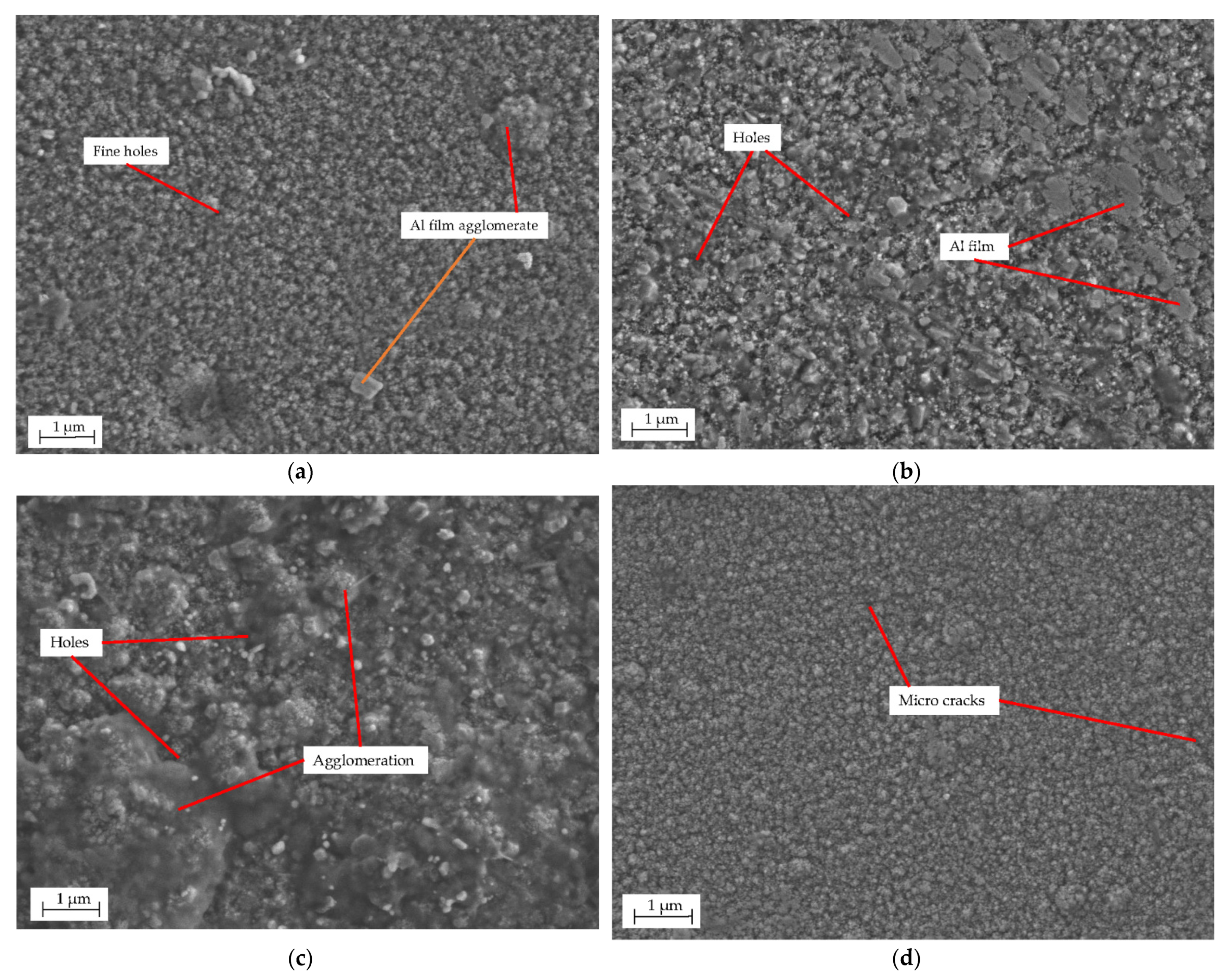
3.2. Surface Morphology and Crystal Orientation of Al Films

Figure 2 shows the surface morphology of Al films deposited on AZ31 magnesium alloys substrate under different sputtering powers.
The sputtering power has a significant effect on the surface morphology of the Al film on the surface of the magnesium alloy substrate. In Figure 2a, when the sputtering power is 50 W, very few particles on the surface of the Al film agglomerate, and there are defects such as fine holes in some areas. When the sputtering power is 75 W, the particles on the surface of the film gradually become larger, and the diameter of the holes on the surface also increases. When the sputtering power increases to 100 W, the agglomeration of particles on the surface of the film becomes particularly obvious, the particle distribution is disordered and the density of the film is reduced; when the sputtering power further increases to 150 W, the surface of the film is dense and uniform, the hole defects are obviously reduced, but there are a few micro cracks in some areas, which may be caused by the stress of the film.
Figure 3 is an XRD diffraction pattern of Al films deposited on magnesium alloys at 50 W, 75 W, 100 W and 150 W sputtering powers. It can be observed that the Al film prepared is polycrystalline state, and there are five Al diffraction peaks, namely, Al(111), Al(200), Al(220), Al(311) and Al(222) when 2θ is in the range of 20° to 90°. The peak values of intensity increase with the increase of sputtering power from 50 W to 150 W.
The grain sizes of the Al film under different sputtering powers can be calculated using the Scherrer formula, as shown in Equation (2):
d = K λ / β cos θ
where d is the grain size of the film (nm), K is the Scherrer constant (0.89), λ is the incident X-ray wavelength (0.15406 nm), θ is the Bragg incidence angle (°) and β is the half peak width (Rad) of the diffraction peak.
The grain sizes of the Al film on the magnesium alloy surface under different sputtering powers are listed in Table 2, and Figure 4 can be fitted accordingly. Figure 4 shows the relationship between the grain size of the Al film on the surface of the magnesium alloy and the sputtering power.
In Figure 4, it can be found that under different sputtering powers, the grain size of the aluminum film varies approximately in the range of 150 nm to 300 nm.

3.3. Corrosion Resistance of Al Films

Figure 5a,b shows the OCP-time and polarization curves and potentiodynamic polarization curves of AZ31 magnesium alloy substrate and Al coating samples with different sputtering powers in 3.5 wt.% NaCl solution at room temperature.
The open circuit potential (Eocp), corrosion potential (Ecorr) and corrosion current density (Icorr) of the magnesium alloy substrate and the Al coating under different sputtering powers are listed in Table 3.
To understand the corrosion behavior, the reference sample of AZ31 magnesium alloy without any film and the four sets of samples (at powers of 50 W, 75 W, 100 W and 150 W) with relatively good compactness and low corrosion current density were immersed in 3.5 wt.% NaCl solution for 2 h. The surface morphology after corrosion is shown in Figure 6.

4. Discussion

4.1. Analysis of Al Film Structure

In Figure 1, there are four characteristic peaks with different diffraction intensities in the range of 2θ from 20° to 90°, which are Al(111), Al(200), Al(220) and Al(311) crystal planes, and the corresponding 2θ angles are 38.474°, 44.722°, 65.099° and 78.232°, respectively. Compared with the four characteristic peaks of Al diffraction standard cards, the maximum deviation is 0.034°, and the scanning step length of the test conditions in this experiment is 0.02°, so the deviation is within a reasonable range of test error. Among the four characteristic peaks, the strongest Al(111) peak at 2θ of 38.474° indicates that the grains of the aluminum film grow in the Al(111) crystal plane preferential orientation. In addition, it is also observed that there is a strong substrate Mg peak. This is because the Al film prepared by the Magnetron Sputtering method in this experiment is nanometer, and the signal collection ability is weak during detection, and the diffraction peaks of the magnesium alloy substrate are too strong, so as to lead to a strong base Mg peak.
In Table 1, the Al film thickness increases sharply with the increase of sputtering power. Since the concentration of Ar ions increases with the increase of sputtering power, there will be a greater amount of Ar ions bombarding the Al sputtering target, which will cause a large amount of deposition of Al atoms on the substrate surface and the increase of the film thickness.

4.2. Analysis of Surface Morphology and Crystal Orientation under Different Sputtering Powers

In Figure 2, the surface morphology of the Al film under different sputtering power changes to different degrees due to the different sputtering atomic energy. When the sputtering power is low, there are fewer Al atoms sputtered on the substrate. In the case, the collision probability between Al atoms is lower, so the energy loss during flying to the substrate will be smaller, and there is also less deposition on the magnesium alloy substrate. The energy of the Al atoms on the upper surface will be higher and will be easier to diffuse and migrate, which is beneficial to fill the original voids and increase the density of the Al film. However, as the sputtering power increases, the number of Al atoms in the chamber increases, which leads to an increase in the collision probability between Al atoms. When Al atoms reach the substrate, the energy is low, which reduces the surface mobility, and at this time, the crystal nucleus forms. The growth mechanism of the aluminum film is dominant [22], which leads to the aluminum film particles being unusually coarse and the surface being rough and loose. In addition, when the sputtering power is increased to a certain extent, although the energy of the atoms deposited is higher, too much nucleation energy may cause excessive internal stress in the film and defects such as cracks [23].
Because the thickness of the Al film prepared under the experimental conditions is very thin, a strong base Mg peak appears during the test. To facilitate observation and analysis, the base peak of the magnesium alloy was removed. It can be found from Figure 3 that the Al film prepared is polycrystalline state, and there are five Al diffraction peaks, namely, Al(111), Al(200), Al(220), Al(311) and Al(222) when 2θ is in the range of 20°~90°. The intensity of Al(111) is higher than that of the others, which indicates that the Al film grows preferentially on the Al(111) crystal plane. It can also be observed from Figure 3 that the diffraction peak of the film increases with the increase of the sputtering power, and the trend of Al(111) is most obvious. When the sputtering power is increased to 75 W, the Al(222) peak also becomes apparent. In addition, when the sputtering power exceeds 100W, the continuous increase of the sputtering power has no significant effect on the orientation of the Al crystal.
The preferred growth of Al film toward the Al(111) crystal plane can be explained from the perspective of energy. Because Al has a face-centered cubic structure, it has the lowest surface energy on the Al(111) close-packed surface [24]. According to the principle of least energy, the particles deposited on the surface of the substrate preferentially nucleate on the Al(111) crystal plane with the lowest surface energy, so the Al film shows a preferential growth of the Al(111) plane.
In Figure 4, with the increase of sputtering power, the grain size of the film gradually increases. When the sputtering power is increased to 100 W, the grain size reaches the maximum value of 285 nm; when the sputtering power is further increased, the grain size begins to gradually decrease. This is because when the sputtering power is too low, only fewer Al atoms leaving the sputtering target surface results in fewer atoms deposited on the substrate. At the same time, when the sputtering power is low, the lower kinetic energy of the Al atom leads to a smaller nucleus of the Al atom. With the increase of sputtering power, the ionization rate of argon gas and the deposition rate increases, and more Al atoms accumulate near the nucleation point, which causes the crystal grains of the aluminum film to grow larger. When the sputtering power is too high (over 100 W), the grain size of the aluminum film decreases. This may be due to the excessive energy of the atoms deposited, which diffuses and migrates on the surface of the substrate by filling vacancies, rearranging, etc., to refine the grains [25].

4.3. Analysis of Corrosion Resistance under Different Sputtering Powers

Based on Figure 5 and Table 3, the Eocp values can reach a stable state after about 150 ss immersion. It is noted that there is little difference between the Eocp values, in which the minimum Eocp value is from the sample with Al film sputtered by 150 W power.
When the sputtering power is increased from 50 W to 75 W, the corrosion current density of the aluminum film in the 3.5 wt.% NaCl solution gradually increases and the corrosion rate also increases; when the sputtering power is increased to 100W, the corrosion current density of the aluminum film is the largest (4.801 × 10⁻⁶ A/cm2) and its corrosion resistance is the worst; when the sputtering power is further increased to 150 W, the corrosion current density of the aluminum film is greatly reduced at this time. The corrosion current density of the magnesium alloy substrate is reduced by about two orders of magnitude, so the corrosion resistance of the aluminum film is the best at this time.
Combined with the SEM morphology analysis in Figure 3, when the sputtering power is 75 W and 100 W, the number of atoms deposited increases at a higher sputtering power, and the film-forming efficiency is also improved as a result. However, with the sputtering power’s continuous increase, it can be found that the grains of the film become extremely coarse and the surface of the film is rough, and the defects increase accordingly when the sputtering power is 100 W. These defects directly provide a diffusion path for the corrosive media, and the corrosive media easily pass through when the defect penetrates the film to reach the film/substrate interface. At this time, a galvanic cell is established between the Al layer and the Mg substrate, and then the substrate as the anode begins to dissolve in the cell with the hydrogen evolution reaction, which eventually leads to the failure of the film. The reactions involved are as follows:
Al → Al3+ + 3e
O2 + 2H2O + 4e → 4OH
Al3+ + 3OH → Al(OH)3
In addition, compared with magnesium alloy substrates, all samples with the Al film sputtered under different powers all exhibit lower corrosion current density, which indicates that magnetron sputtering Al film can effectively improve the corrosion resistance of magnesium alloys.
Generally, the cathode and anode regions of the polarization curve show important corrosion characteristics, especially in the anode region. In Figure 5, the curve of the sample at the sputtering power of 50 W has an obvious passivation phenomenon, but the value of Icorr is smaller than that of the reference sample of bare AZ31 magnesium alloy. The reason for this may be the thin thickness and bad oxidation film quality, although the oxidation film can prevent the anodizing process and acts as a barrier layer for the electrolyte, hindering its contact with the substrate surface. However, with the increase of the applied potential, the curve of the sample at the potential Eb has a turning point, which indicates that the oxidation film’s passivation film has broken down. With the increase of the applied potential, the thickness of the Al film increases, and the film quality is improved, so the value of Icorr decreases greatly. The improvement of corrosion resistance can be judged by the electrode potential’s shift in the positive direction and the reduction of the current density. According to the curves, Ecorr shifts from −1.602 V to −1.357 V in the positive direction at the same time that Icorr deceases from 1.269 × 10⁻⁶ to 7.033 × 10⁻⁷ when the sputtering power increase from 50 W to 150 W. So, the corrosion rate of 150 W is lower than that of 50 W.
As shown in Figure 6a, the substrate surface of magnesium alloy sample becomes uneven, and there are many obvious cracks after soaking for 2 h, which indicates serious corrosion on the surface of the magnesium sample. Compared with the magnesium alloy reference sample, in the Al film sputtered by the powers of 50 W and 75 W, there are relatively large cracks in local areas as shown in Figure 6b,c; meanwhile, it is observed in Figure 6d that there are a large amount of corrosion pits on the Al film sputtered by the power of 100 W. Compared with surface sputtered by 100 W, there are only a few shallow corrosion pits and many white corrosion products as shown in Figure 6e. In addition, with reference to Figure 2d, the Al film sample sputtered by the power of 150 W has a few micro cracks, but the corrosion current density of the sample is significantly lower than that of the Al film under other powers. This is mainly because the thickness of Al film sputtered by power of 150 W is large, and the cracks on the film surface are small and shallow and cannot penetrate the entire film. When the corrosive media flow into the small cracks, the corrosion products will accumulate here and have a certain barrier effect on the corrosion reaction, which effectively slows down the corrosion rate.

5. Conclusions

In this paper, Nano Al films were prepared on the surface of AZ31 magnesium alloy samples by DC Magnetron Sputtering, and the effects of sputtering power on the microstructure and corrosion resistance were investigated. The main conclusions are as follows:
(1) The Al film prepared by DC Magnetron Sputtering is in a polycrystalline state and has a face-centered cubic structure. The sputtering power has a significant effect on the structure of the Al film. When the sputtering power is increased, the grain size of the Al film first increases and then decreases. When the sputtering power exceeds 100 W, continuing to increase the sputtering power has no insignificant effect on the orientation of the Al crystal.
(2) When the sputtering power is 150 W, the density of the Al film is relatively big. Compared with the magnesium alloy, the corrosion current density of the samples with an Al film are reduced by about two orders of magnitude, and their corrosion resistances are improved.
(3) The corrosion resistance of the Al film sputtered on the surface of the magnesium alloy sample varies with the sputtering power. Compared with a low sputtering power, the Al film sputtered by high power has the most excellent corrosion resistance, but a too high sputtering power will cause micro cracks in the Al film, which will adversely affect the corrosion resistance of the Al film.

Author Contributions

Conceptualization, Z.G.; methodology, Z.G. and Z.A.; validation, C.S., D.Y. and L.D.; formal analysis, C.S.; investigation, D.Y., X.Z. and Z.A.; data curation, L.D. and X.Z.; writing—original draft preparation, D.Y. and Z.G.; funding acquisition, Z.G.; project administration, Z.G. All authors have read and agreed to the published version of the manuscript.

Funding

The research was funded by the Scientific and Technological Research Program of Chongqing Science and Technology Bureau (Grant No. cstc2019jcyj-msxmX0761), the Scientific and Technological Research Program of Chongqing Municipal Education Commission (Grant No. KJQN201800731) and the Scientific and Technological Research Program of Chongqing Jiaotong University (Grant No. 16JDKJC-A005).

Data Availability Statement

Not applicable.

Conflicts of Interest

The authors declare no conflict of interest.

References

  1. Powell, B.R.; Krajewski, P.E.; Luo, A.A. Magnesium alloys for lightweight powertrains and automotive bodies. In Materials Design and Manufacturing for Lightweight Vehicles; Mallick, P.K., Ed.; Woodhead Publishing Ltd.: Cambridge, UK, 2010; pp. 114–168. [Google Scholar]
  2. Czerwinski, F. Controlling the ignition and flammability of magnesium for aerospace applications. Corros. Sci. 2014, 86, 1–16. [Google Scholar] [CrossRef]
  3. Kumar, D.; Phanden, R.K.; Thakur, L. A review on environment friendly and lightweight Magnesium-Based metal matrix composites and alloys. Mater. Today Proc. 2020, 38, 359–364. [Google Scholar] [CrossRef]
  4. Zhang, W.; Zhao, H.; Hu, X.; Ju, D. A novel processing for CNT-Reinforced Mg-Matrix laminated composites to enhance the electromagnetic shielding property. Coatings 2021, 11, 1030. [Google Scholar] [CrossRef]
  5. Zheng, Y.; Li, N. Novel Magnesium alloys developed for biomedical application: A review. J. Mater. Sci. Technol. 2013, 29, 489–502. [Google Scholar]
  6. Liu, S.; Li, G.; Qi, Y.; Peng, Z.; Liang, J. Corrosion and tribocorrosion resistance of MAO-based composite coating on AZ31 magnesium alloy. J. Magnes. Alloy. 2021. In Press. [Google Scholar] [CrossRef]
  7. Lin, R.; Liu, C.; Wang, F.; Jia, Y.; Ding, Y.; Ban, G.; Li, Z. Development of corrosion surface modification technology for magnesium alloys. Surf. Technol. 2016, 45, 124–131. [Google Scholar]
  8. Song, G.L.; Atrens, A. Corrosion mechanisms of magnesium alloys. Adv. Eng. Mater. 1999, 1, 11–33. [Google Scholar]
  9. Esmaily, M.; Svensson, J.E.; Fajardo, S.; Birbilis, N.; Frankel, G.S.; Virtanen, S.; Arrabal, R.; Thomas, S.; Johanssonet, L.G. Fundamentals and advances in magnesium alloy corrosion. Prog. Mater. Sci. 2017, 89, 92–193. [Google Scholar] [CrossRef]
  10. Gusieva, K.; Davies, C.; Scully, J.; Birbilis, N. Corrosion of magnesium alloys: The role of alloying. Int. Mater. Rev. 2015, 60, 169–194. [Google Scholar] [CrossRef]
  11. Saji, V.S. Review of rare-earth-based conversion coatings for magnesium and its alloys. J. Mater. Res. Technol. 2019, 8, 5012–5035. [Google Scholar] [CrossRef]
  12. Tu, X.; Miao, C.; Yang, Z.; Xu, Y.; Li, J. Plasma Electrolytic Oxidation of Magnesium alloy AZ31B in electrolyte containing Al2O3 sol as additives. Materials 2018, 11, 1618. [Google Scholar] [CrossRef] [Green Version]
  13. Wu, L.; Zhao, J.; Xie, Y.; Yang, Z. Progress of electroplating and electroless plating on magnesium alloy. Trans. Nonferrous Met. Soc. China 2010, 20, 630–637. [Google Scholar] [CrossRef]
  14. Rolink, G.; Weisheitb, A.; Biermann, T.; Bobzin, K.; Öte, M.; Linke, T.F.; Schulz, C.; Kelbassa, I. Investigations of laser clad, thermal sprayed and laser remelted AlSi20-coatings on magnesium alloy AZ31B under constant and cycling thermal load. Surf. Coat. Technol. 2014, 259, 751–758. [Google Scholar] [CrossRef]
  15. Xin, Y.; Liu, C.; Zhang, W.; Jiang, J.; Tang, G.; Tian, X.; Chu, P. Electrochemical behavior. Al2O3/Al coated surgical az91 magnesium alloy in simulated body fluids. J. Electrochem. Soc. 2008, 155, C178–C182. [Google Scholar] [CrossRef]
  16. Xin, Y.; Liu, C.; Huo, K.; Tang, G.; Tian, X.; Chu, P.K. Corrosion behavior of ZrN/Zr coated biomedical AZ91 magnesium alloy. Surf. Coat. Technol. 2009, 203, 2554–2557. [Google Scholar] [CrossRef]
  17. Singh, A.; Harimkar, S.P. Laser surface engineering of magnesium alloys: A review. JOM 2012, 64, 716–733. [Google Scholar] [CrossRef] [Green Version]
  18. Nakamura, K.; Shimada, Y.; Miyashita, T. Effect of vapor pressure during the steam coating treatment on structure and corrosion resistance of the Mg(oh)2/Mg-Al LDH composite film formed on mg alloy az61. Materials 2018, 11, 1659. [Google Scholar] [CrossRef] [Green Version]
  19. Zhang, J.; Yang, D.; Ou, X. Microstructures and properties of aluminum film and its effect on corrosion resistance of AZ31B substrate. Trans. Nonferrous Met. Soc. China 2008, 18, s312–s317. [Google Scholar] [CrossRef]
  20. Wu, G.; Wang, A.; Ding, K.; Xu, C.; Dai, W.; Xu, A. Fabrication of Cr coating on AZ31 magnesium alloy by magnetron sputtering. Trans. Nonferrous Met. Soc. China 2008, 18, s329–s333. [Google Scholar] [CrossRef]
  21. McCafferty, E. Validation of corrosion rates measured by the Tafel extrapolation method. Corros. Sci. 2005, 47, 3202–3215. [Google Scholar] [CrossRef]
  22. Chen, E.; Peng, K.; Yang, W.; Zhu, J.; Li, D.; Zhou, L. Effects of Al coating on corrosion resistance of sintered NdFeB magnet. Trans. Nonferrous Met. Soc. China 2014, 24, 2864–2869. [Google Scholar] [CrossRef]
  23. Tang, J.; Niu, D.; Tai, Z.; Hu, X. Deposition of highly c-axis-oriented ScAlN thin films at different sputtering power. J. Mater. Sci. 2017, 28, 5512–5517. [Google Scholar] [CrossRef]
  24. Zhang, J.; Xu, K. Dependence of strain-energy density on the grain orientation in fcc-polycrystalline films. Acta Phys. Sin. 2002, 51, 2562–2565. [Google Scholar]
  25. Hua, Y.; Zhu, A.; Chen, R.; Guo, L. Microstructure and electrical properties of Al nano-particle films by DC magnetron sputtering. J. Funct. Mater. 2015, 46, 4071–4075. [Google Scholar]
Figure 1. XRD diffraction pattern of Al film sputtered on magnesium alloy surface.
Metals 11 01522 g001
Figure 2. Surface morphology of Al film deposited on magnesium alloy surface under different sputtering power. (a) 50 W; (b) 75 W; (c) 100 W; (d) 150 W.
Metals 11 01522 g002
Figure 3. XRD spectrum of Al film deposited on magnesium alloy surface under different sputtering power.
Metals 11 01522 g003
Figure 4. Relationship between grain size and sputtering power of Al film sputtered on magnesium alloy surface.
Metals 11 01522 g004
Figure 5. OCP (a) and PDP (b) curves of Al film prepared under different sputtering power in 3.5 wt.% NaCl solution.
Metals 11 01522 g005
Figure 6. Surface morphology of samples immersed in 3.5 wt.% NaCl solution for 2 h: (a) AZ31 without film; (b) 50 W; (c) 75 W; (d) 100 W; (e) 150 W.
Metals 11 01522 g006aMetals 11 01522 g006b
Table 1. Thickness of Al film prepared under different sputtering power.
Sputtering Power/WFilm Thickness/nm
50320
75372
100670
1501243
Table 2. Grain sizes of Al film on magnesium alloy surface under different sputtering powers.
Sputtering Power/WGrain Size/nm
50161
75220
100285
150192
Table 3. Ecorr and Icorr values of Al films prepared under different sputtering power in 3.5 wt.% NaCl solution.
Sputtering Power/WEocp (V)Ecorr (V/SCE)Icorr (A/cm2)
Uncoated (AZ31 Substrate)−1.554−1.5381.538 × 10−5
50−1.548−1.6021.269 × 10−6
75−1.559−1.5192.534 × 10−6
100−1.555−1.5064.801 × 10−6
150−1.561−1.3577.033 × 10−7
Publisher’s Note: MDPI stays neutral with regard to jurisdictional claims in published maps and institutional affiliations.

