
The Strength of Inconel 625, Manufactured by the Method of Direct Laser Deposition under Sub-Microsecond Load Duration

 ,
, 
Abstract
:1. Introduction
2. Materials and Methods
3. Results and Discussion
- residual tension, which is eliminated by thermal treatment;
- pores located perpendicular to the direction of deposition;
- features of the grain microstructure that are formed, depending on the parameters of direct laser deposition.
4. Conclusions
Author Contributions
Funding
Institutional Review Board Statement
Informed Consent Statement
Data Availability Statement
Conflicts of Interest
References
- Debroy, T.; Wei, H.L.; Zuback, L.S.; Mukherjee, T.; Elmer, J.W.; Milewski, J.O.; Beese, A.M.; Wilson-Heid, A.; De, A.; Zhang, W. Additive manufacturing of metallic components—Process, structure and properties. Prog. Mater. Sci. 2018, 92, 112–224. [Google Scholar] [CrossRef]
- Promakhov, V.V.; Savinykh, A.S.; Dubkova, Y.A.; Grunt, N.V.; Razorenov, S.V. Strength Properties of Aluminum-Oxide Ceramics Prepared by the Additive Manufacturing Method under Shock-Wave Loading. Tech. Phys. Lett. 2018, 44, 898–901. [Google Scholar] [CrossRef]
- Gorsse, S.; Hutchinson, C.; Goune, M.; Banerjee, R. Additive manufacturing of metals: A brief review of the characteristic microstructures and properties of steels, Ti-6Al-4V and high-entropy alloys. Sci. Technol. Adv. Mater. 2017, 18, 584–610. [Google Scholar] [CrossRef] [Green Version]
- Promakhov, V.; Zhukov, A.; Ziatdinov, M.; Turichin, G.; Perminov, A. Inconel 625/TiB 2 metal matrix composites by direct laser deposition. Metals 2019, 9, 141. [Google Scholar] [CrossRef] [Green Version]
- Basak, A.; Das, S. Epitaxy and Microstructure Evolution in Metal Additive Manufacturing. Annu. Rev. Mater. Res. 2016, 46, 125–149. [Google Scholar] [CrossRef]
- Wise, J.L.; Adams, D.P.; Nishida, E.E.; Song, B.; Maguire, M.C.; Carroll, J.; Reedlunn, B.; Bishop, J.E.; Palmer, T.A. Comparative shock response of additively manufactured versus conventionally wrought 304L stainless steel. AIP Conf. Proc. 2017, 1793, 100015. [Google Scholar]
- Brown, A.D.; Ameri, A.H.; Gregg, A.; Austin, D.C.; Escobedo, J.P.; Hazell, P.J.; East, D.; Quadir, M.Z. Dynamic mechanical response of additive manufactured Ti-6Al-4V. AIP Conf. Proc. 2018, 1979, 070008. [Google Scholar]
- Jones, D.R.; Fensin, S.J.; Dippo, O.; Beal, R.A.; Livescu, V.; Martinez, D.T.; Trujillo, C.P.; Florando, J.N.; Kumar, M.; Gray, G.T. Spall fracture in additive manufactured Ti-6Al-4V. J. Appl. Phys. 2016, 120, 135902. [Google Scholar] [CrossRef]
- Razorenov, S.V.; Garkushin, G.V.; Savinykh, A.S.; Klimova-Korsmik, O.G.; Shalova, S.A.; Gushchina, M.O. Dynamic strength of the VT6 titanium alloy obtained by direct laser growth. Phys. Mesomech. 2021, 24, 17–25. [Google Scholar]
- Zaretsky, E.; Stern, A.; Frage, N. Dynamic response of AlSi10Mg alloy fabricated by selective laser melting. Mater. Sci. Eng. A 2017, 688, 364–370. [Google Scholar] [CrossRef]
- Gray, G.T.; Knapp, C.M.; Jones, D.R.; Livescu, V.; Fenshin, S.; Morrow, B.M.; Trujillo, C.P.; Martinez, D.T.; Valdez, J.A. Structure/property characterization of spallation in wrought and additively manufactured tantalum. AIP Conf. Proc. 2018, 1979, 060002. [Google Scholar]
- Klimova-Korsmik, O.; Turichin, G.; Mendagaliev, R.; Razorenov, S.; Garkushin, G.; Savinykh, A.; Korsmik, R. High-Strain Deformation and Spallation Strength of 09CrNi2MoCu Steel Obtained by Direct Laser Deposition. Metals 2021, 11, 1305. [Google Scholar] [CrossRef]
- Barker, L.M.; Hollenbach, R.E. Laser interferometer for measuring high velocities of any reflecting surface. J. Appl. Phys. 1972, 43, 4669. [Google Scholar] [CrossRef]
- Wong, H.; Dawson, K.; Ravi, G.A.; Howlett, L.; Jones, R.O.; Sutcliffe, C.J. Multi-Laser Powder Bed Fusion Benchmarking—Initial Trials with Inconel 625. Int. J. Adv. Manuf. Technol. 2019, 105, 2891–2906. [Google Scholar] [CrossRef] [Green Version]
- Verdi, D.; Garrido, M.A.; Munez, C.J.; Poza, P. Mechanical properties of Inconel 625 laser cladded coatings: Depth sensing indentation analysis. Mater. Sci. Eng. A 2014, 598, 15–21. [Google Scholar] [CrossRef]
- Mazur, M.; Benoit, M.; Easton, M.; Brandt, M. Selective laser melting of Inconel 625 alloy with reduced defect formation. J. Laser Appl. 2020, 32, 022058. [Google Scholar] [CrossRef]
- Kanel, G.I. Distortion of the Wave Profiles in an Elastoplastic Body upon Spalling. J. Appl. Mech. Tech. Phys. 2001, 42, 358–362. [Google Scholar] [CrossRef]
- Kanel, G.I.; Razorenov, S.V.; Fortov, V.E. Shock-Wave Phenomena and the Properties of Condensed Matter, 1st ed.; Springer: New York, NY, USA, 2004. [Google Scholar]
- Zaretsky, E.B.; Kanel, G.I.; Razorenov, S.V.; Baumung, K. Impact strength properties of nickel-based refractory superalloys at normal and elevated temperatures. Int. J. Impact Eng. 2005, 31, 41–54. [Google Scholar] [CrossRef]
- Reinhart, W.; Chhabildas, L. Strength properties of coors AD995 alumina in the shocked state. Int. J. Impact Eng. 2003, 29, 601–619. [Google Scholar] [CrossRef]
- Whelchel, R.L.; Mehoke, D.S.; Lyer, K.A.; Sanders, T.H., Jr.; Thadhani, N.N. Dynamic yielding and fracture of grade 4 titanium in plate impact experiments. J. Appl. Phys. 2016, 119, 115901. [Google Scholar] [CrossRef]
- Kanel, G.I.; Garkushin, G.V.; Savinykh, A.S.; Razorenov, S.V.; Atroshenko, S.A. High-Rate Deformation and Fracture of 15Kh2NMFA Steel under Impact Loading at Normal and Elevated Temperatures. Tech. Phys. 2020, 65, 420–427. [Google Scholar] [CrossRef]
- Garkushin, G.V.; Savinykh, A.S.; Razorenov, S.V.; Kanel, G.I. Influence of High-Temperature Annealing on the Resistance to High Strain Rate and Fracture of Tantalum at Temperatures of 20 and 500 °C. Tech. Phys. 2019, 64, 674–679. [Google Scholar] [CrossRef]
- Saveleva, N.V.; Bayandin, Y.V.; Savinykh, A.S.; Garkushin, G.V.; Razorenov, S.V.; Naimark, O.B. The Formation of Elastoplastic Fronts and Spall Fracture in AMg6 Alloy under Shock-Wave Loading. Tech. Phys. Lett. 2018, 44, 823–826. [Google Scholar] [CrossRef]
- Duffy, T.S.; Ahrens, T.J. Dynamic response of molybdenum shock compressed at 1400 °C. J. Appl. Phys. 1994, 76, 835. [Google Scholar] [CrossRef] [Green Version]
- Huang, W.; Zan, X.; Nie, X.; Gong, M.; Wang, Y.; Xia, Y. Experimental study on the dynamic tensile behavior of a poly-crystal pure titanium at elevated temperatures. Mater. Sci. Eng. A 2007, 443, 33–41. [Google Scholar] [CrossRef]
- Li, C.; Li, B.; Huang, J.Y.; Ma, H.H.; Zhu, M.H.; Zhu, J.; Luo, S.N. Spall damage of a mild carbon steel: Effects of peak stress, strain rate and pulse duration. Mater. Sci. Eng. A 2016, 660, 139–147. [Google Scholar] [CrossRef]
- Kanel, G.I.; Savinykh, A.S.; Garkushin, G.V.; Razorenov, S.V. Effects of temperature and strain on the resistance to high-rate deformation of copper in shock waves. J. Appl. Phys. 2020, 128, 115901. [Google Scholar] [CrossRef]


| Manufacturer | Chemical Composition of Powders, wt.% | ||||||||
|---|---|---|---|---|---|---|---|---|---|
| Ni | Cr | Fe | Mo | Si | Nb | Mn | O2 | Other | |
| Inconel 625 Höganäs AB | Main | 20.8 | 0.51 | 8.9 | 0.43 | 3.51 | 0.37 | 0.07 | 0.08 |
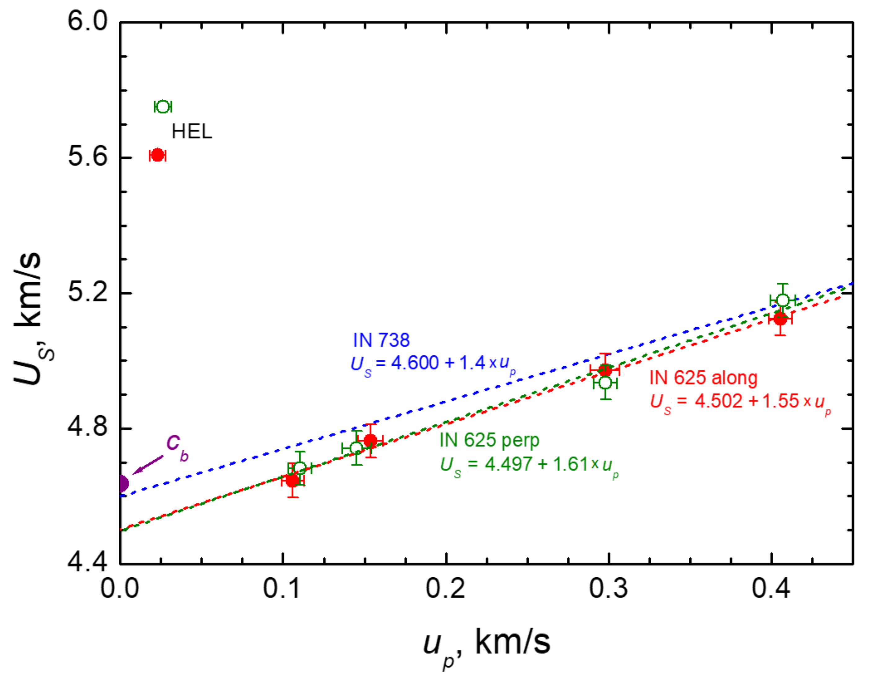
| Sample | hs, mm | himp, mm/ Material | Vimp, m/s | US, km/s | up, km/s |
|---|---|---|---|---|---|
| Along the Deposition Direction | |||||
| In625_2 | 1.944 | 0.465/Cu | 675 ± 10 | 4.972 | 0.2978 |
| In625_3 | 1.957 | 0.395/W | 638 ± 10 | 5.124 | 0.4055 |
| In625_4 | 1.952 | 0.786/Cu | 234 ± 10 | 4.646 | 0.106 |
| In625_51 | 1.940 | 0.463/Cu | 350 ± 10 | 4.763 | 0.1538 |
| Perpendicular to the Deposition Direction | |||||
| pIn625_6 | 2.067 | 0.480/Cu | 350 ± 10 | 4.741 | 0.1452 |
| pIn625_7 | 2.007 | 0.802/Cu | 234 ± 10 | 4.682 | 0.1105 |
| pIn625_8 | 1.964 | 0.480/Cu | 675 ± 10 | 4.935 | 0.298 |
| pIn625_9 | 1.995 | 0.396/W | 638 ± 10 | 5.178 | 0.407 |
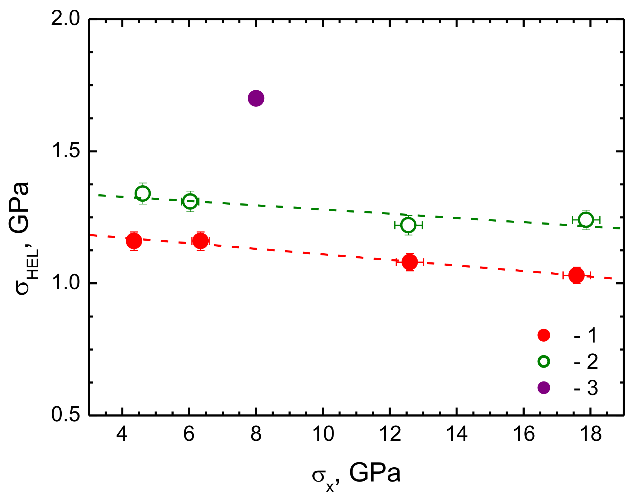
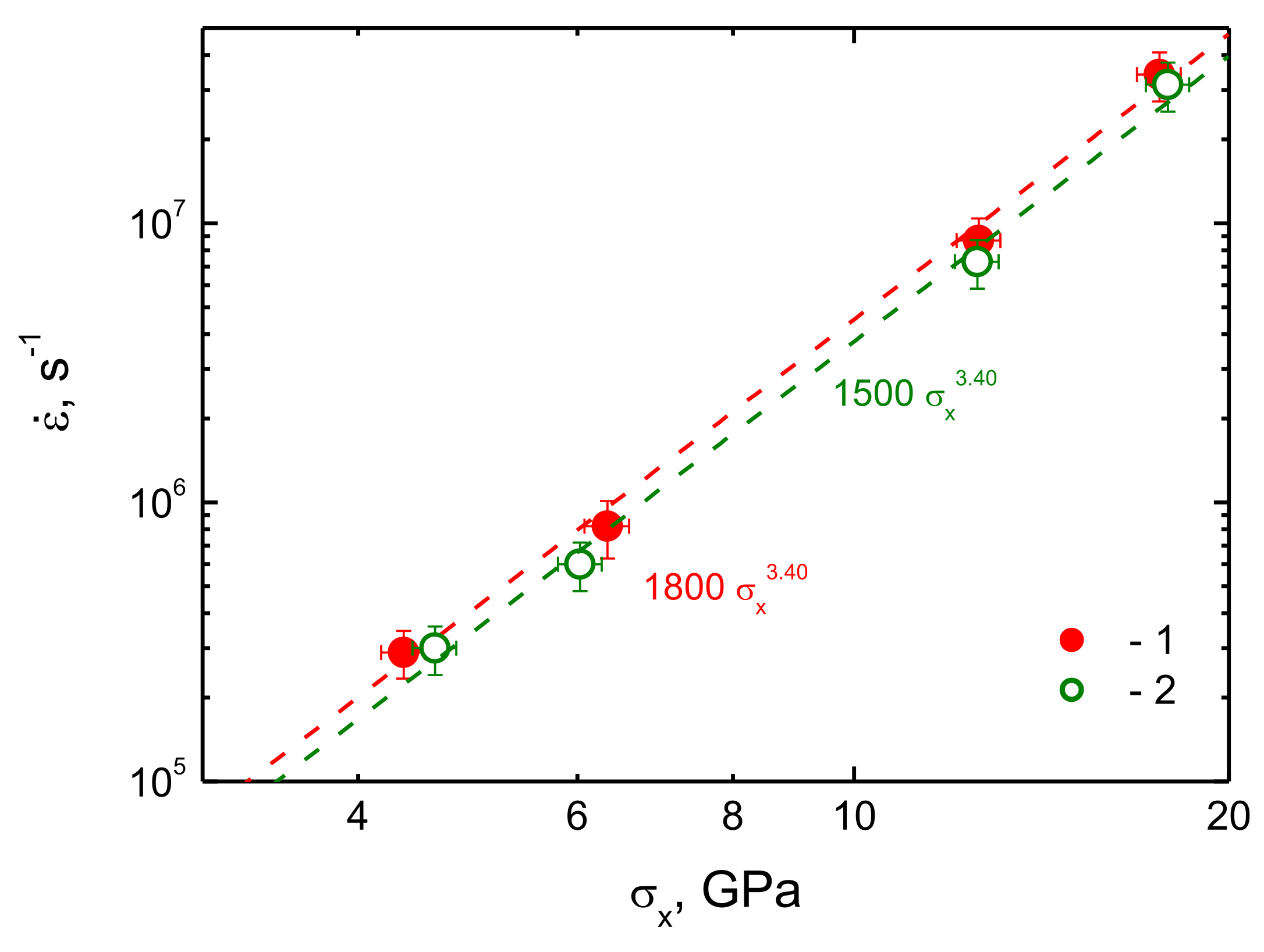
| Sample | uHEL, m/s | σHEL, GPa | Δufs, m/s | σsp, GPa | hsp, mm | σx, GPa | ||
|---|---|---|---|---|---|---|---|---|
| Along the Deposition Direction | ||||||||
| In625_2 | 45.6 | 1.08 | 213.3 | 4.80 | 3.20 × 10⁵ | 0.47 | 8.68 × 10⁶ | 12.60 |
| In625_3 | 43.5 | 1.03 | 204.6 | 4.58 | 3.07 × 10⁵ | 0.41 | 34.13 × 10⁶ | 17.59 |
| In625_4 | 49.3 | 1.16 | – | – | – | – | 0.29 × 10⁶ | 4.35 |
| In625_51 | 49.3 | 1.16 | 197.5 | 4.35 | 2.52 × 10⁵ | 0.60 | 0.82 × 10⁶ | 6.34 |
| Perpendicular to the Deposition Direction | ||||||||
| pIn625_6 | 54.1 | 1.31 | 202.6 | 4.40 | 2.23 × 10⁵ | 0.64 | 0.60 × 10⁶ | 6.03 |
| pIn625_7 | 55.5 | 1.34 | – | – | – | – | 0.30 × 10⁶ | 4.61 |
| pIn625_8 | 50.3 | 1.22 | 209.6 | 4.70 | 2.92 × 10⁵ | 0.49 | 7.27 × 10⁶ | 12.56 |
| pIn625_9 | 51.2 | 1.24 | 207.6 | 4.47 | 2.49 × 10⁵ | 0.38 | 31.37 × 10⁶ | 17.87 |
Publisher’s Note: MDPI stays neutral with regard to jurisdictional claims in published maps and institutional affiliations. |
© 2021 by the authors. Licensee MDPI, Basel, Switzerland. This article is an open access article distributed under the terms and conditions of the Creative Commons Attribution (CC BY) license (https://creativecommons.org/licenses/by/4.0/).
Share and Cite
Promakhov, V.; Schulz, N.; Vorozhtsov, A.; Savinykh, A.; Garkushin, G.; Razorenov, S.; Klimova-Korsmik, O. The Strength of Inconel 625, Manufactured by the Method of Direct Laser Deposition under Sub-Microsecond Load Duration. Metals 2021, 11, 1796. https://doi.org/10.3390/met11111796
Promakhov V, Schulz N, Vorozhtsov A, Savinykh A, Garkushin G, Razorenov S, Klimova-Korsmik O. The Strength of Inconel 625, Manufactured by the Method of Direct Laser Deposition under Sub-Microsecond Load Duration. Metals. 2021; 11(11):1796. https://doi.org/10.3390/met11111796
Chicago/Turabian StylePromakhov, Vladimir, Nikita Schulz, Alexander Vorozhtsov, Andrey Savinykh, Gennady Garkushin, Sergey Razorenov, and Olga Klimova-Korsmik. 2021. "The Strength of Inconel 625, Manufactured by the Method of Direct Laser Deposition under Sub-Microsecond Load Duration" Metals 11, no. 11: 1796. https://doi.org/10.3390/met11111796
APA StylePromakhov, V., Schulz, N., Vorozhtsov, A., Savinykh, A., Garkushin, G., Razorenov, S., & Klimova-Korsmik, O. (2021). The Strength of Inconel 625, Manufactured by the Method of Direct Laser Deposition under Sub-Microsecond Load Duration. Metals, 11(11), 1796. https://doi.org/10.3390/met11111796