Article

Microstructure and Mechanical Properties of Friction Stir Welded AA6061/AA6061 + 40 vol% SiC Plates

by
Sara Señorís-Puentes
1,*,
Ricardo Fernández Serrano
1,
Gaspar González-Doncel
1,
Jesper Henri Hattel
2 and
Oleg V. Mishin
2,*
1
Department of Physical Metallurgy, CENIM, C.S.I.C., Av. de Gregorio del Amo, 8, 28040 Madrid, Spain
2
Department of Mechanical Engineering, Technical University of Denmark, DK-2800 Kgs. Lyngby, Denmark
*
Authors to whom correspondence should be addressed.
Metals 2021, 11(2), 206; https://doi.org/10.3390/met11020206
Submission received: 29 December 2020 / Revised: 15 January 2021 / Accepted: 20 January 2021 / Published: 23 January 2021

Abstract

:
The feasibility of butt friction stir welding (FSW) of a metal matrix composite (MMC) with a very high SiC particle content to a monolithic aluminum alloy is tested in this work. It is demonstrated for the first time that sound FSW joints can be obtained between an AA6061 aluminum plate and a thick MMC plate consisting of AA6061 reinforced with 40 vol% SiC particles. The joints withstand tensile testing, with ductile failure taking place in a soft region of the heat-affected zone on the alloy side. Metallographic examination of the MMC side after FSW reveals curved bands, where both the frequency of SiC particles and hardness are significantly lower than those in any other region on the MMC side. It is suggested that these bands are produced by transporting the alloy material to the MMC side, where the alloy is mechanically mixed with the MMC.

1. Introduction

Aluminum-base metal matrix composites (MMCs) are currently used in products where increased specific stiffness and strength or/and increased wear resistance are required, e.g., in engine components and braking systems. Since Al-base MMCs are more expensive than traditional aluminum alloys, there is a clear economical reason to use them only in the most critical parts of a product, whereas other parts can be made of conventional monolithic alloys. This necessitates joining of dissimilar materials, which can conveniently be done using friction stir welding (FSW) [1,2,3,4,5,6]. In the FSW process, a rotating tool generates heat due to friction, which softens and plasticizes materials to be joined. The plasticized materials move in a stir zone, thus making a joint. As a solid-state process, FSW prevents chemical reactions associated with conventional fusion welding operations. In addition, friction stir welds are characterized by lower porosity compared to joints obtained by fusion welding.
FSW was successfully applied for joining of commercial Al alloys and Al-base MMCs containing 15 to 25 vol% ceramic particles [7,8,9,10,11,12,13,14]. To the best of our knowledge, there are no publications describing FSW of Al/Al MMCs with a much higher particle content. Apparently, FSW of such dissimilar materials represents a greater challenge, especially for thick plates, which warrants dedicated experiments. The aim of this work is to test the feasibility of FSW for butt joining thick plates of an Al alloy and an Al-base MMC with a very high volume fraction (40%) of ceramic particles. Reinforcement particles in the MMC were chosen to be SiC and the AA6061 alloy was both the MMC matrix and the monolithic material, to which the MMC plate was friction stir welded. FSW was conducted in the present experiment on 8-mm-thick plates which were significantly thicker than other friction stir welded Al/Al MMC plates described in several previous publications [6,7,8,9,10,11,12].
The microstructure of the as-received and friction stir welded plates is characterized in this work using optical microscopy and scanning electron microscopy (SEM). Mechanical properties of the welded samples are assessed via Vickers hardness measurements and tensile testing. The results obtained are compared with those reported for other aluminum-base MMCs friction stir welded to aluminum alloys.

2. Materials and Methods

Two 8 mm-thick plates were used for butt FSW in this experiment. One plate was an AA6061 + 40 vol% SiC (6061/SiC/40p) MMC produced by Materion using a powder metallurgy route. Another plate was a commercial AA6061 alloy in temper T651 (stress-relieved after artificial aging). Prior to welding, edges of each plate were milled along the longitudinal direction. FSW was carried out using a PDS-4 I-Stir machine (I-STIR Technology, Shoreview, MN, USA) at AIMEN (Porriño, Spain) with the AA6061 plate placed on the retreating side and the MMC plate placed on the advancing side. A tool with a 7.6-mm-long tapered conical WC–Co pin having three flat faces at 120° and a concave shoulder with a diameter of 25 mm was used for FSW. The diameter of the tapered pin decreased from 7 mm in the upper part to approximately 6 mm in the lower part. Welding parameters were initially chosen to be similar to those previously applied for optimizing FSW of AA2124/SiC/25p MMC plates [15]. The initial parameters were then adjusted based on preliminary trials. In particular, the traverse speed was reduced from 15 mm/min to 5 mm/min to prevent rapid tool fracture during FSW. For the welds studied in the present work, the tilt angle was 1.5° and the rotational speed was 450 rev/min. Three welded samples were produced by FSW along the longitudinal direction of the plates with no tool offset. The vertical force and spindle torque values were continuously recorded by the PDS-4 I-Stir machine. The average values calculated for steady-state conditions were 13 kN and 54 Nm for the vertical force and spindle torque, respectively. For one of the welds, temperature was monitored during FSW using thermocouples placed in Ø1.5 mm holes drilled at 20 mm from the joint line. The maximum temperature recorded on the retreating side was 378 °C. On the advancing side, the maximum recorded temperature reached 325 °C. This welded sample was used for microstructural examinations and hardness measurements.
Microstructures in the as-received conditions and in the welded sample with known temperature profile were characterized in the cross-section of the plates, i.e., in the section which was perpendicular to the welding direction. A Zeiss Axio Vert.A1 microscope (Carl Zeiss Microscopy GmbH, Jena, Germany) was used for taking optical micrographs. The surface of each sample was initially ground on abrasive papers and then polished on a polishing cloth using a diamond paste with a nominal particle size of 1 µm. Low-magnification optical micrographs of the entire sample cross-section were taken after etching the surface with Barker’s reagent. To facilitate electron backscatter diffraction (ESBD), the surface of the AA6061 alloy was additionally polished electrochemically using a Struers A2 electrolyte. Several regions were investigated in different locations of the samples using secondary electron and backscattered electron (BSE) modes in a Zeiss Supra 35 field emission gun scanning electron microscope. Energy dispersive X-ray spectroscopy (EDS) was applied for chemical analysis of particles. Grain structures in the AA6061 alloy were investigated using the EBSD technique with a step size of 1 µm. In the EBSD data, low-angle boundaries (LABs) were defined as those with misorientation angles θ = 1.5–15°. High-angle boundaries (HABs) were defined as those with θ > 15°.
Vickers hardness was measured using a Struers DuraScan 70-G5 tester (Struers ApS, Ballerup, Denmark) on the mechanically polished cross-sections. In the as-received plates, the hardness was measured using a load of 1 kgf and a dwell time of 10 s. In the welded plate, the measurements were carried out automatically by traversing along the mid-thickness of the plate with a step size of 1.5 mm between individual measurements. A load of 500 gf and a dwell time of 10 s were applied for these measurements. Additionally, hardness was measured selectively within the distinct bands observed on the MMC side. From each of the three welded samples, one dog bone shaped specimen with a gauge length of 60 mm and a width of 8 mm was produced by wire electrical discharge machining, with the joint being perpendicular to the tensile axis (see Figure 1). The specimens were then tensile tested at room temperature using an Instron 1362 machine at an initial strain rate of 5 × 10⁻⁴ s−1. Images of the fracture surface were taken in a Hitachi S-4800 scanning electron microscope (Hitachi High-Tech Corporation, Japan).

3. Results and Discussion

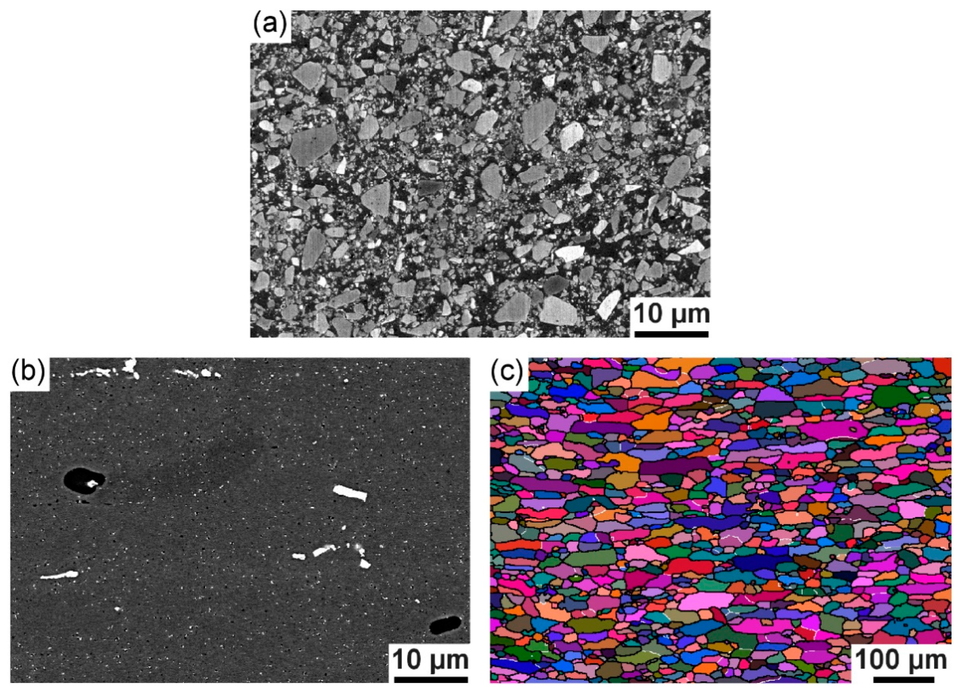
3.1. As-Received Materials

The microstructure observed in the cross-section of the as-received plates is presented in Figure 2. It is seen that the size of SiC particles in the MMC varies from the submicron range to approximately 6 µm (Figure 2a). The hardness of this material is 185 ± 7 HV. Particles of different sizes are also observed in the AA6061 plate (see Figure 2b). The EDS analysis conducted on several large particles indicated that in addition to Al the particles contained Fe (15 to 29 wt%), Si (4 to 10 wt%), Cu (1 to 3 wt%), Mn and Cr (<2 wt% each). Due to the comparatively high concentration of heavy elements, such particles produce strong atomic number contrast in Al and appear bright in BSE images. The AA6061 alloy in the aged condition is expected to also contain nanosized needle-shaped precipitates composed of Mg and Si [16,17,18,19]. Although such needle-shaped precipitates are not distinguishable in the available BSE images, the high hardness measured in the as-received sample, 106 ± 2 HV, provides clear evidence that this material indeed contains a large number of nanoprecipitates. EBSD orientation mapping of the AA6061 alloy reveals recrystallized grains with an average size of 15 μm (see Figure 2c). The EBSD data also indicate that 94% of all grain boundaries in the alloy are HABs.

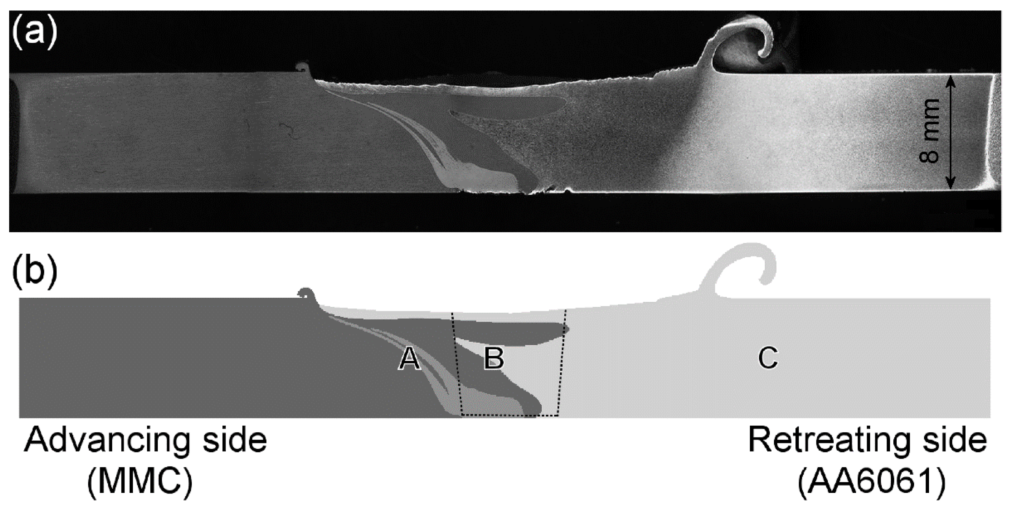
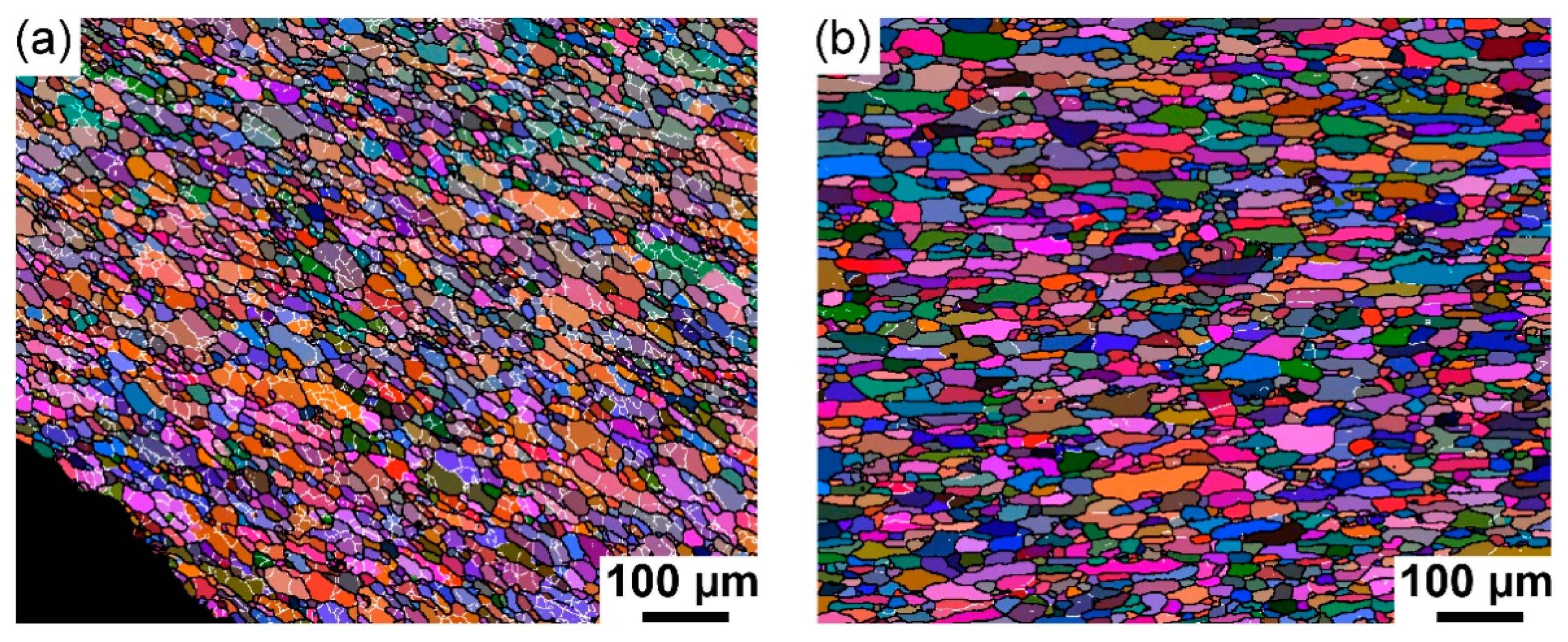
3.2. Microstructure after FSW

FSW results in complete joints which are free of voids and cracks as is evident from Figure 3a. The fact that sound welds can be produced by FSW between a commercial Al alloy and Al-base MMC with the ceramic particle content as high as 40 vol% is significant since no similar reports were found in the literature.
The top surface along the joint shown in Figure 3a is concave-shaped, so that the plate thickness along the joint is almost 1 mm smaller than the thickness of the initial plates. Excess flash produced by the tool is seen in the micrograph, with the flash height being 0.4 mm on the MMC side and 3.8 mm on the alloy side. Contrasting areas with clearly observable interfaces are also seen in the welded plate. These contrasting areas correspond to different structures illustrated schematically in Figure 3b. The top surface along the weld represents a continuous layer of the AA6061 alloy (light gray in Figure 3b) penetrating into the MMC side (dark gray in Figure 3b). The thickness of this surface layer on the MMC side is 0.4–0.7 mm. The MMC/AA6061 interface zigzags along the joint and the two materials do not seem to be blended along the interface (see Figure 4).
A very different microstructure is observed within an area which appears to be one broad band close to the plate bottom and which splits into two narrower and curved individual bands at 1.5 mm above the bottom surface on the advancing side of the plate. When measured at the plate mid-thickness, one band is 0.3 mm wide, while another band is 0.9 mm wide. This area is shown in a different shade of gray in Figure 3b and the individual bands near the mid-thickness are also presented in Figure 5a. In the optical micrograph in Figure 5a, MMC regions appear dark, while the bands are lighter. Furthermore, a layered structure with alternating light and darker layers can be distinguished within these bands, where the darker layers contain more SiC particles than the light layers (see Figure 5a,b). The pattern formed by the alternating layers within the bands resembles intercalated features in so-called onion rings frequently observed in friction stir welds [1,2,3,4]; however, there seems to be no regular spacing between the layers within these bands. Inspection of several joints indicated that the band morphology varied from weld to weld and also in different locations of one weld. For example, bands broken near the mid-thickness and zigzagging features were also observed.
The difference in the microstructure across the interface between the 3-mm-wide layered band (LB) and the MMC is shown in more detail in Figure 5c,d. Compared to continuous MMC areas, the layered regions contain fewer SiC particles and plenty of Fe-rich particles, seen as bright features in the BSE images (Figure 5d). It can, therefore, be suggested that the bands are produced by transporting the AA6061 alloy from the retreating side to the advancing side, where the alloy is mechanically mixed with the MMC. This suggestion is further supported by hardness data in Section 3.3.
Orientation maps produced by the EBSD technique in regions B and C (see Figure 3b) of the AA6061 alloy are shown in Figure 6. Region B corresponds to the stir zone, defined here as the zone where the pin was located during FSW, while region C corresponds to the heat-affected zone (HAZ). It is seen that the microstructure in the stir zone (Figure 6a) is very different from that in the base material and the HAZ (see Figure 2c and Figure 6b). In particular, grains in the stir zone are frequently subdivided by low-angle boundaries, while the fraction of such boundaries is small in the other regions of the AA6061 alloy (Table 1). The presence of many low-angle boundaries is typical of hot-deformed aluminum, and similar microstructures were observed in stir zones of other 6xxx series Al alloys [20,21,22]. Due to grain subdivision by such deformation-induced boundaries, the mean (sub)grain size d is smaller, 9 µm, in the stir zone than in the HAZ and the base material (Table 1). Another effect of the presence of many LABs in the stir zone is that the aspect ratio of grains and subgrains in this zone is somewhat smaller than in the other areas (see Table 1).

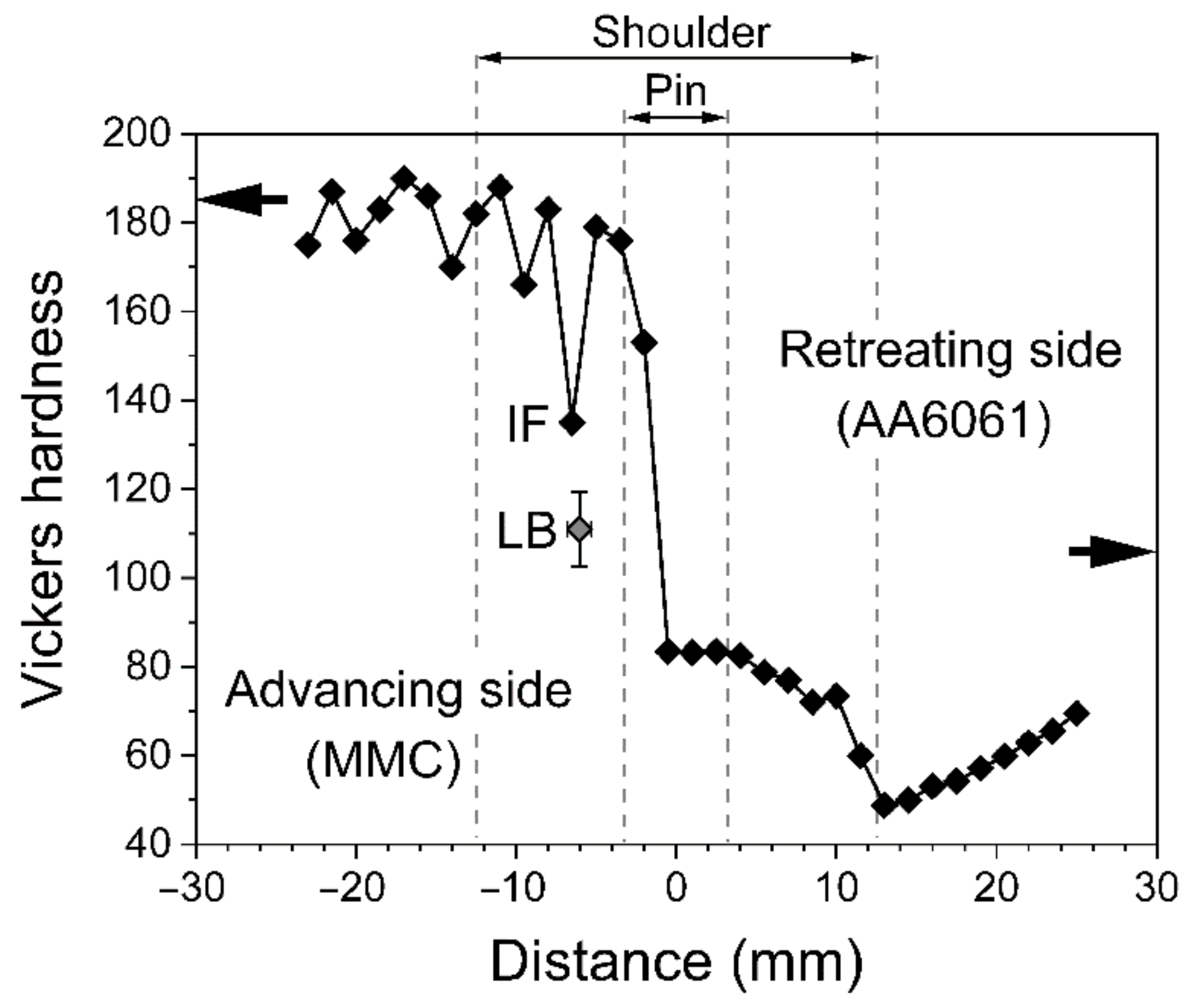
3.3. Variation of Hardness in the Welded Plate

Vickers hardness is shown in Figure 7 as a function of distance from the joint measured along the mid-thickness of the welded plate. On the advancing side, hardness fluctuates around 180 HV at a distance of 12 mm to 23 mm from the joint being close to the hardness of the base MMC material. The difference between individual HV values on the advancing side becomes more significant closer to the joint, with one location where the hardness decreases down to 135 HV. Inspection of the surface showed that this value (marked “IF” in Figure 7) was recorded along the LB/MMC interface (see the indent in Figure 5a). On the retreating (AA6061) side, hardness drops to approximately 84 HV within the region stirred by the pin, followed by a slight reduction within 5 mm to 10 mm from the joint line (see Figure 7). Another pronounced drop in hardness down to 49 HV is observed in the AA6061 plate at 13 mm from the joint, i.e., in the HAZ.
The significant softening in the HAZ of the AA6061 plate is attributed to partial dissolution of nanoprecipitates due to high-temperature heating, which is a common observation for 6xxx series alloys [16,17,18,19]. It should be noted that the temperature at 20 mm from the joint of the examined sample was measured to reach 378 °C on the AA6061 side (see Section 2), and the actual temperature at 13 mm from the joint could be higher. Taking into account that previous transmission electron microscopy studies of AA6061-T651 plates revealed very low frequencies of fine particles in the HAZ exposed to peak temperatures of 360 to 370 °C [16], it is considered that in our experiment, the peak temperature in the HAZ of the AA6061 alloy was sufficient to reduce the frequency of nanoprecipitates formed by aging. Since such fine precipitates are the major contributor to the hardness and strength in age-hardenable alloys, their loss inevitably softens the material, leading to ductile failure in the softest and weakest HAZ region on the alloy side. The higher hardness in the stir zone of the AA6061 plate implies that reduction in the frequency of fine precipitates in this zone is partly counterbalanced by greater boundary strengthening as compared to those in the HAZ. Beyond 13 mm from the joint, the hardness of the AA6061 plate increases, though it does not reach the level of the as-received material even at 30 mm from the joint (see Figure 7).
To record hardness inside the layered bands on the advancing side, nine individual HV measurements were made inside these bands near the mid-thickness and the average hardness was found to be 111 ± 8 HV (marked “LB” in Figure 7). This value is significantly lower than the hardness of the adjacent MMC regions and appreciably higher than the hardness measured at a similar distance from the joint line in the HAZ on the retreating side (see Figure 7). This observation is consistent with the suggestion that the bands represent a mixture of the MMC and the alloy material transported from the retreating side.

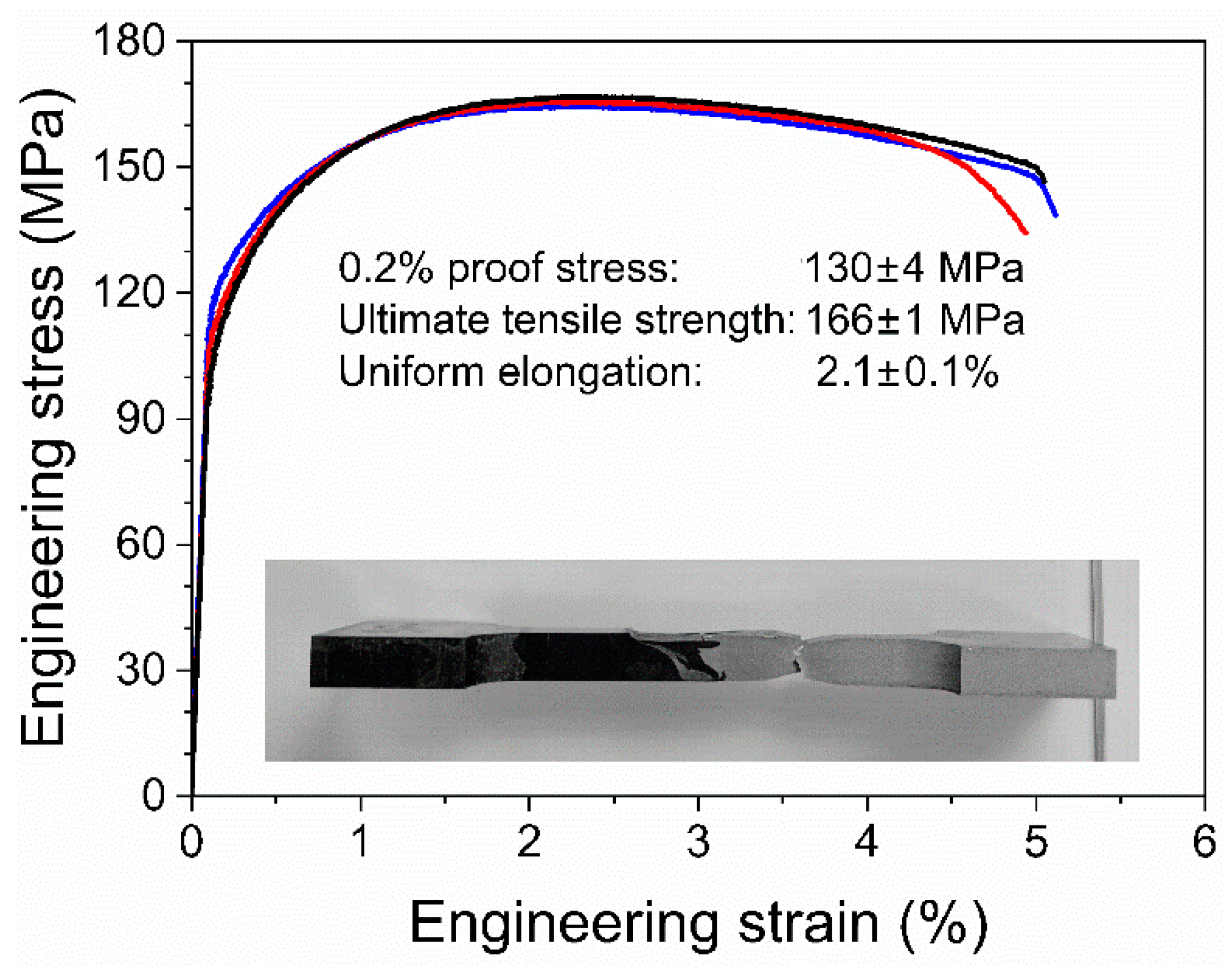
3.4. Tensile Test Data

Stress–strain curves, average values of strength and elongation are shown in Figure 8 along with the optical micrograph of one of the tensile tested specimens. The obtained joints were sufficiently strong to withstand the tensile test, and the specimens broke in the HAZ region of the AA6061 plate. This result is different from that reported for several other dissimilar Al alloy/Al-base MMC materials [10,11,14], where tensile test specimens failed either along the joint or on the MMC side. It is evident that failure of our specimens occurred after considerable necking (see Figure 8). The presence of characteristic dimples on the fracture surface also indicates predominantly ductile fracture by formation and coalescence of voids (Figure 9).
The average ultimate tensile strength (UTS) for the tested specimens is 166 MPa, which is at least 18% higher than the UTS in friction stir welded AA6061/Al + 20 wt% Mg2Si plates [11] and almost 40% higher than that reported for as-welded AA6061-O/AA6061 + 20 vol% SiC plates [12], though it is lower than the average strength, 208 MPa, measured in AA6061-T6/AA6061 + 20 vol% SiC plates [13]. Considering that the strength of the welded plate is controlled by the strength of the softest HAZ region on the AA6061 side, it is expected that the overall performance of the AA6061/AA6061 + 40 vol% SiC welds can be improved by increasing the strength of the HAZ. For example, it is known that greater strength in monolithic AA6061-T651 plates can be achieved by an increase in the traverse speed [16,23]. Since FSW at higher speeds reduces the exposure time at a high temperature and can thus lead to less significant changes in the distribution of fine precipitates, it is possible that some improvement in strength can be obtained by increasing the traverse speed also for the materials studied in this work. On the other hand, it is pertinent to note that our attempts to conduct FSW of these materials at higher speeds (10–15 mm/min) resulted in rapid tool fracture. It is therefore apparent that further experiments are required to establish optimum combinations of tools and welding parameters for FSW of Al-base MMCs with a very high particle content to Al alloys. An alternative approach to improve the strength of friction stir welded Al/Al MMC plates is to apply post-weld heat treatments [12,19], though it is obvious that this approach can only be effective for age-hardenable alloys.

4. Conclusions

(1)
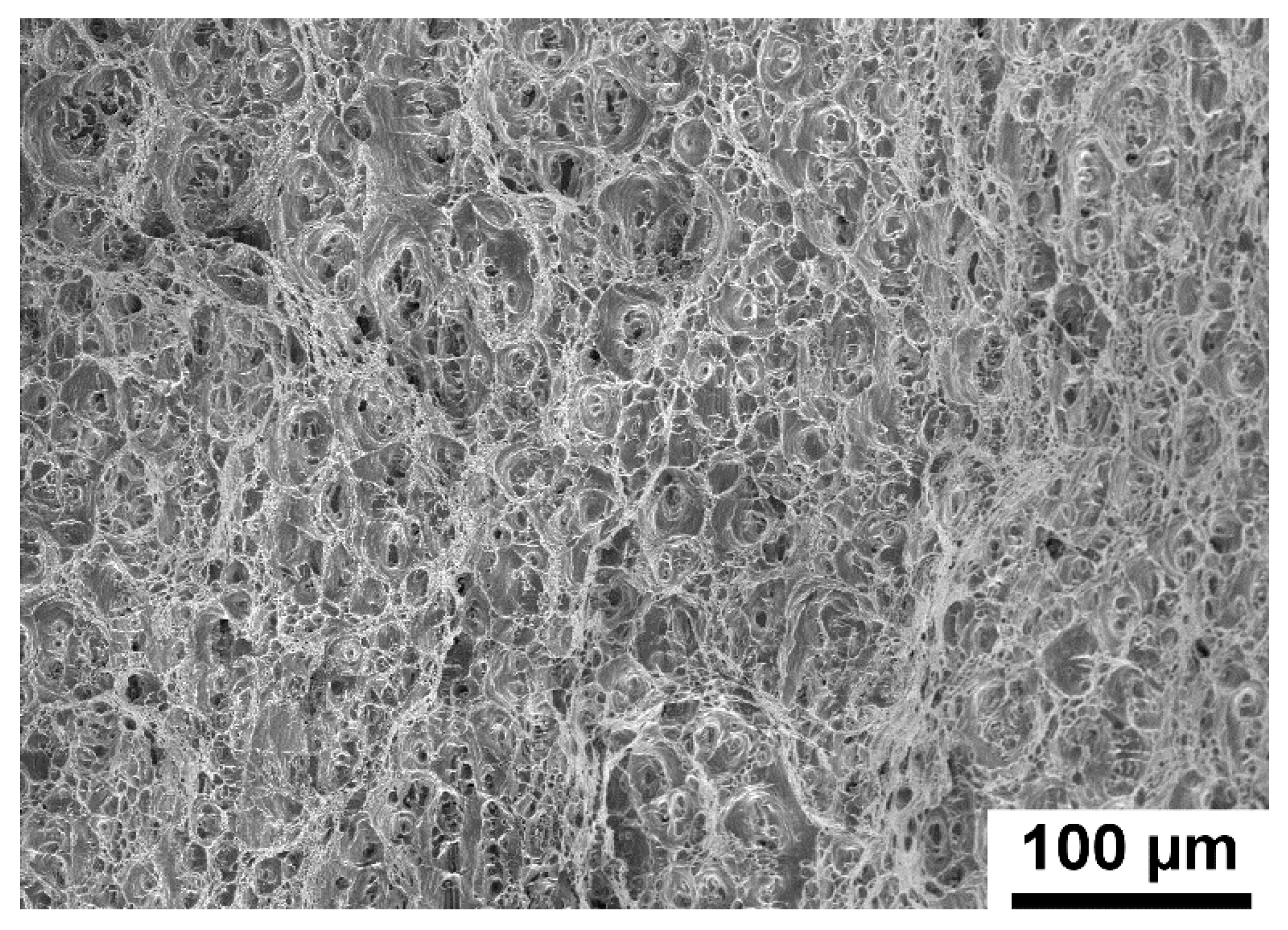
FSW of a 8-mm-thick AA6061 + 40 vol% SiC MMC plate to an AA6061-T651 alloy plate results in sound butt joints free of cavities and cracks. The joints withstand tensile testing, with failure taking place in a soft region of the heat-affected zone on the alloy side. The average tensile strength in the welded plates is measured to be 166 MPa and the uniform elongation is 2.1%.
(2)
The microstructure in the stir zone on the alloy side is refined by deformation-induced boundaries and is harder than the heat-affected zone. The frequency of low-angle boundaries near the joint is 35% and the average (sub)grain size is 9 µm.
(3)
The MMC side of the welded plate contains curved bands where the frequency of SiC particles and hardness are both significantly lower than those in any other region of the MMC plate. It is suggested that these bands are produced by transporting the alloy material to the MMC plate where the alloy is mechanically mixed with the MMC.

Author Contributions

Conceptualization, R.F.S. and G.G.-D.; methodology, R.F.S., G.G.-D., and O.V.M.; formal analysis, S.S.-P., R.F.S., and O.V.M.; investigation, S.S.-P., R.F.S., and O.V.M.; resources, R.F.S., G.G.-D., and J.H.H.; writing—original draft preparation, S.S.-P.; writing—review and editing, R.F.S., G.G.-D., O.V.M., and J.H.H.; supervision, R.F.S. and G.G.-D.; funding acquisition, R.F.S. and G.G.-D. All authors have read and agreed to the published version of the manuscript.

Funding

This research was funded by MINECO, Spain, under contract MAT2017-83825-C4-1-R.

Institutional Review Board Statement

Not applicable.

Informed Consent Statement

Not applicable.

Data Availability Statement

The data presented in this study are available from the corresponding author, O.V.M., upon reasonable request.

Acknowledgments

The authors thank D. Verdera for his assistance during practical FSW at the Technology Centre AIMEN, S.S. Munch for his assistance with specimen preparation and hardness measurements, and M.R. Sonne for useful discussions.

Conflicts of Interest

The authors declare no conflict of interest.

References

  1. Murr, L.E. A Review of FSW research on dissimilar metal and alloy systems. J. Mater. Eng. Perform. 2010, 19, 1071–1089. [Google Scholar] [CrossRef]
  2. Simar, A.; Avettand-Fènoël, M.-N. State of the art about dissimilar metal friction stir welding. Sci. Technol. Weld. Join. 2016, 22, 389–403. [Google Scholar] [CrossRef]
  3. Wang, X.; Pan, Y.; Lados, D.A. Friction stir welding of dissimilar Al/Al and Al/Non-Al alloys: A Review. Met. Mater. Trans. A 2018, 49, 2097–2117. [Google Scholar] [CrossRef]
  4. Peng, G.; Yan, Q.; Hu, J.; Chen, P.; Chen, Z.; Zhang, T. Effect of forced air cooling on the microstructures, tensile strength, and hardness distribution of dissimilar friction stir welded AA5A06-AA6061 joints. Metals 2019, 9, 304. [Google Scholar] [CrossRef] [Green Version]
  5. Peng, G.; Ma, Y.; Hu, J.; Jiang, W.; Huan, Y.; Chen, Z.; Zhang, T. Nanoindentation hardness distribution and strain field and fracture evolution in dissimilar friction stir-welded AA 6061-AA 5A06 aluminum alloy joints. Adv. Mater. Sci. Eng. 2018, 1–11. [Google Scholar] [CrossRef] [Green Version]
  6. Park, S.; Joo, Y.; Kang, M. Effect of backing plate materials in micro-friction stir butt welding of dissimilar AA6061-T6 and AA5052-H32 aluminum alloys. Metals 2020, 10, 933. [Google Scholar] [CrossRef]
  7. Wert, J. Microstructures of friction stir weld joints between an aluminium-base metal matrix composite and a monolithic aluminium alloy. Scr. Mater. 2003, 49, 607–612. [Google Scholar] [CrossRef]
  8. Xiao, B.; Wang, D.; Bi, J.; Zhang, Z.; Ma, Z. Friction stir welding of SiCp/Al composite and 2024 Al alloy. Mater. Sci. Forum 2010, 638, 1500–1505. [Google Scholar] [CrossRef]
  9. Yahya, B.; Serdal, D.; Bozkurt, Y.; Duman, S. The effect of welding parameters on the mechanical and microstructural properties of friction stir welded dissimilar AA 3003-H24 and 2124/SiC/25p-T4 alloy joints. Sci. Res. Essays 2011, 6, 3702–3716. [Google Scholar] [CrossRef] [Green Version]
  10. Guo, J.; Gougeon, P.; Chen, X.-G. Microstructure evolution and mechanical properties of dissimilar friction stir welded joints between AA1100-B4C MMC and AA6063 alloy. Mater. Sci. Eng. A 2012, 553, 149–156. [Google Scholar] [CrossRef]
  11. Moharami, A.; Razaghian, A.; Babaei, B.; Ojo, O.; Šlapáková, M. Role of Mg2Si particles on mechanical, wear, and corrosion behaviors of friction stir welding of AA6061-T6 and Al-Mg2Si composite. J. Compos. Mater. 2020, 54, 4035–4057. [Google Scholar] [CrossRef]
  12. Öztoprak, N.; Yeni, C.E.; Kiral, B.G. Effects of post-weld heat treatment on the microstructural evolution and mechanical properties of dissimilar friction stir welded AA6061+SiCp/AA6061-O joint. Lat. Am. J. Solids Struct. 2018, 15, 49. [Google Scholar] [CrossRef]
  13. Öztoprak, N.; Yeni, Ç.E.; Kıral, B.G. Dissimilar friction stir butt welding of AA6061-T6 and AA6061/SiCp composite: Microstructural characteristics, impact toughness, hardness, strength under transverse impact. Trans. Indian Inst. Met. 2018, 72, 511–521. [Google Scholar] [CrossRef]
  14. Cioffi, F.; Ibañez, J.; Fernandez, R.; González-Doncel, G. The effect of lateral off-set on the tensile strength and fracture of dissimilar friction stir welds, 2024Al alloy and 17%SiC/2124Al composite. Mater. Des. 2015, 65, 438–446. [Google Scholar] [CrossRef] [Green Version]
  15. Fernández, R.; Ibáñez, J.; Cioffi, F.; Verdera, D.; González-Doncel, G. Friction stir welding of 25%SiC/2124Al composite with optimal mechanical properties and minimal tool wear. Sci. Technol. Weld. Join. 2017, 22, 526–535. [Google Scholar] [CrossRef]
  16. Liu, F.; Ma, Z. Influence of tool dimension and welding parameters on microstructure and mechanical properties of friction-stir-welded 6061-T651 aluminum alloy. Met. Mater. Trans. A 2008, 39, 2378–2388. [Google Scholar] [CrossRef]
  17. Feng, A.; Chen, D.; Ma, Z. Microstructure and low-cycle fatigue of a friction-stir-welded 6061 aluminum alloy. Met. Mater. Trans. A 2010, 41, 2626–2641. [Google Scholar] [CrossRef]
  18. Maisonnette, D.; Suery, M.; Nelias, D.; Chaudet, P.; Epicier, T. Effects of heat treatments on the microstructure and mechanical properties of a 6061 aluminium alloy. Mater. Sci. Eng. A 2011, 528, 2718–2724. [Google Scholar] [CrossRef] [Green Version]
  19. Sato, Y.S.; Kokawa, H. Distribution of tensile property and microstructure in friction stir weld of 6063 aluminum. Met. Mater. Trans. A 2001, 32, 3023–3031. [Google Scholar] [CrossRef]
  20. Sato, Y.S.; Urata, M.; Kokawa, H. Parameters controlling microstructure and hardness during friction-stir welding of precipitation-hardenable aluminum alloy 6063. Met. Mater. Trans. A 2002, 33, 625–635. [Google Scholar] [CrossRef]
  21. Fonda, R. Development of grain structure during friction stir welding. Scr. Mater. 2004, 51, 243–248. [Google Scholar] [CrossRef]
  22. Mishin, O.; Östensson, L.; Godfrey, A. Comparative microstructural characterization of a friction-stir-welded aluminum alloy using TEM and SEM-based techniques. Met. Mater. Trans. A 2006, 37, 489–496. [Google Scholar] [CrossRef]
  23. Lim, S.; Kim, S.; Lee, C.-G.; Kim, S. Tensile behavior of friction-stri-welded Al 6061-T651. Met. Mater. Trans. A 2004, 35, 2829–2835. [Google Scholar] [CrossRef]
Figure 1. Dimensions (in mm) of tensile test specimens machined from the welded samples.
Metals 11 00206 g001
Figure 2. Microstructure in the cross-section of the as-received plates: (a) secondary electron image of the MMC plate; (b) BSE image; (c) orientation map for the AA6061 plate. In (c), LABs and HABs are shown as white and black lines, respectively. The normal direction is vertical.
Metals 11 00206 g002
Figure 3. Optical micrograph (a) and schematic illustration (b) of the cross-section of the friction stir welded AA6061/MMC plate. Dark-gray and light-gray regions correspond to the MMC and the AA6061 alloy, respectively. Intermediate shading corresponds to the area which appears to be one broad band close to the plate bottom and which splits into two narrower individual bands on the advancing side. Letters A to C in (b) indicate the inspected regions, while dashed lines indicate the approximate location of the pin during FSW.
Metals 11 00206 g003
Figure 4. Secondary electron image from the central region of the joint (region B in Figure 3b) showing the interface between the MMC and the AA6061 alloy in the friction stir welded plate.
Metals 11 00206 g004
Figure 5. Images from region A in Figure 3b: (a,b) optical micrographs showing the layered bands (LB) on the MMC side at different magnifications. The dark rectangular feature in (a) is an indent produced during hardness measurements; (c) secondary electron image from a region along the LB/MMC interface; (d) BSE image from another region along the LB/MMC interface. In this BSE image, ceramic SiC particles appear dark, while Fe-rich intermetallic particles appear bright due to atomic number contrast.
Metals 11 00206 g005
Figure 6. Microstructure in different regions on the AA6061 side of the friction stir welded AA6061/MMC plate analyzed using the EBSD technique: (a) stir zone (region B in Figure 3b) where EBSD pattern indexing was possible only for the AA6061 alloy and where the black corner corresponds to the MMC; (b) HAZ (region C in Figure 3b). LABs and HABs are shown as white and black lines, respectively.
Metals 11 00206 g006
Figure 7. Vickers hardness as a function of distance from the joint measured along the mid-thickness of the friction stir welded AA6061/MMC plate. The deep cusp on the advancing side marked “IF” corresponds to the hardness recorded along the LB/MMC interface (see Figure 5a). The gray symbol (marked “LB”) indicates the average value measured within the layered bands near the mid-thickness. The arrows in the plot indicate the level of hardness in the as-received MMC and AA6061 plates.
Metals 11 00206 g007
Figure 8. Stress–strain curves and average parameters of strength and elongation. Optical micrograph shows a tested specimen machined from the welded plate used for microstructural characterization and hardness measurements.
Metals 11 00206 g008
Figure 9. Secondary electron image showing the fracture surface in the HAZ of the AA6061 alloy.
Metals 11 00206 g009
Table 1. Parameters of the microstructure determined using EBSD in the AA6061 alloy.
Zoned (µm)Aspect RatioFraction of LABs (%)
Stir zone91.735
HAZ152.35
Base material152.26
Publisher’s Note: MDPI stays neutral with regard to jurisdictional claims in published maps and institutional affiliations.

