Article

Modelling of Technological Parameters of Aluminium Melt Refining in the Ladle by Blowing of Inert Gas through the Rotating Impeller

1
Faculty of Materials Science and Technology, VŠB-Technical University of Ostrava, 17. listopadu 2172/15, 70800 Ostrava, Czech Republic
2
Faculty of Engineering Materials and Metallurgy, Silesian University of Technology, Krasińskiego 8, 40-019 Katowice, Poland
*
Author to whom correspondence should be addressed.
Metals 2021, 11(2), 284; https://doi.org/10.3390/met11020284
Submission received: 21 December 2020 / Revised: 17 January 2021 / Accepted: 3 February 2021 / Published: 6 February 2021
(This article belongs to the Special Issue Advances in Production and Refining of Metals)

Abstract

:
The presented paper deals with the use of physical modelling to study the degassing process of aluminium melts in the refining ladle by blowing inert gas through a rotating impeller. For the purposes of physical modelling, a plexiglass model in a scale of 1:1 is used for the operating ladle. Part of the physical model is a hollow shaft used for gas supply that is equipped with an impeller and two baffles. The degassing process of aluminium melt by blowing of inert gas is simulated at physical modelling by a decrease of dissolved oxygen in the model liquid (water). This paper is aimed at the evaluation of laboratory experiments that were obtained by the method of physical modelling. Attention is focused on the assessment of relevant parameters for the degassing process—rotary impeller speeds, volume flow rate of inert gas, the distance of the impeller from the bottom of the refining ladle, and impeller variant. The preliminary results of physical modelling show that the optimal results of the refining process are achieved by using the F2A 190 impeller.

1. Introduction

Emphasis has increasingly been placed on the melt refining processes for removing gases (hydrogen) [1,2,3,4], metallic impurities (sodium, calcium, lithium, etc.), and non-metallic impurities (oxides, nitrides, borides, carbides, etc.) during processing due to the increasing demand of aluminium casting quality. The method of blowing inert gas, so-called refining gas, through a rotating impeller into the ladle presents the most common operational technology in order to reduce the content of impurities in a molten aluminium, e.g., hydrogen [5,6,7].
The degassing technology by using inert gas is based on the Sieverts Law. It is possible to reduce the gas content in the melt by reducing its partial pressure in an inert gas bubble, according to the Sieverts Law. The main optimization parameters are the rotary impeller speed and the amount of blown inert gas [8,9,10]. The efficiency of this rotary refining depends on the creation of fine bubbles with a high interphase surface, wide-spread distribution, residence time of its effect in the melt, and mostly on the wide-spread dispersion of bubbles into the whole volume of the refining ladle. This is most affected by the rotary impeller speeds and the amount of blown inert gas. The geometry of the impeller and its influence on the distribution and dispersion of inert gas bubbles, the formation of vortices, and the overall homogenization of the melt is also an equally important parameter [11,12,13].
The optimisation of the degassing process is difficult under operating conditions. Therefore, in laboratory conditions, so-called modelling is used, where the original prototype is replaced by a model. The technology of modelling is divided to two basic methods. In numerical modelling, the process is described by a mathematical model that is formed of a system of partial differential equations. In the case of physical modelling, a method is used in which the real system is replaced by a tangible physical model, which is as close as possible to the behaviour of the real system. The basis of physical modelling consists in the targeted utilisation of the similarities of the processes that take place within the actual device and its model. In this method, both the prototype and the model have the same physical basis. Thus, the fluid flow is modelled again by the fluid flow, but on a certain scale of lengths, velocity volume flow rates, viscosities, etc. The condition for the transfer of results from the model to the work is the similarity of the processes taking place in the model and the work. One of the advantages of physical modelling is the possibility of visualising processes that contribute to understanding the processes taking place in real systems. The results achieved on the model can predict the real system behaviour in the course of various process changes [14,15,16,17,18].
The aim of the present article is the introduce on the evaluation of methodical laboratory experiments aimed at the proposal and testing of the developed methods of degassing during physical modelling.

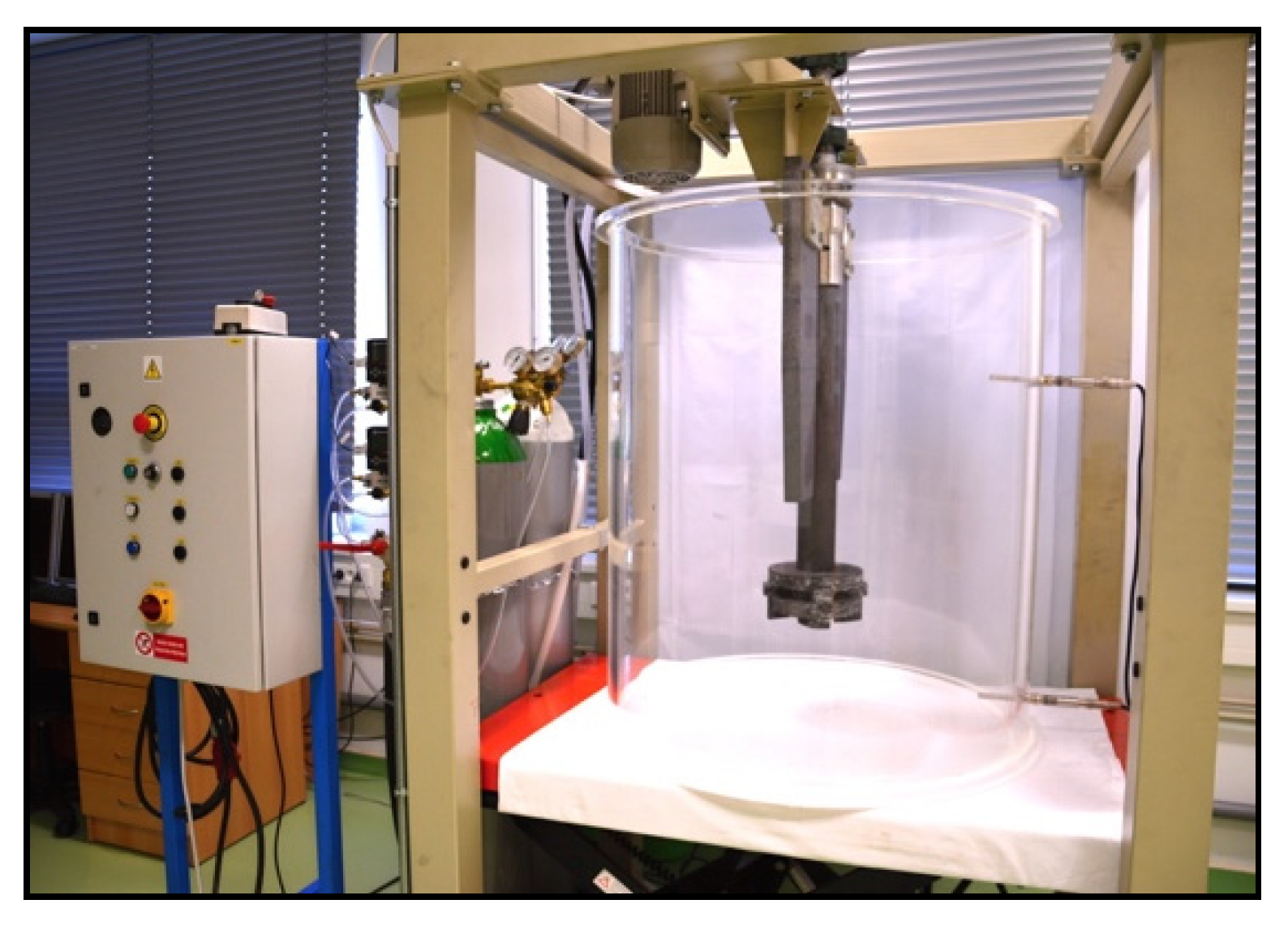
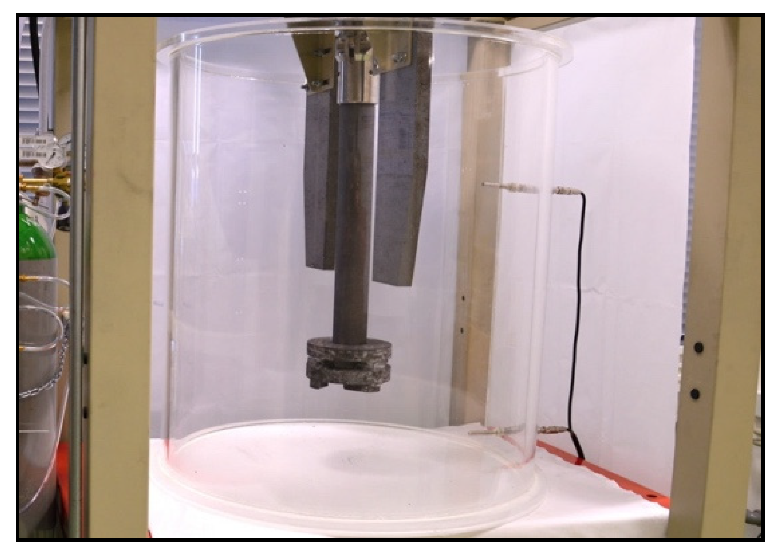
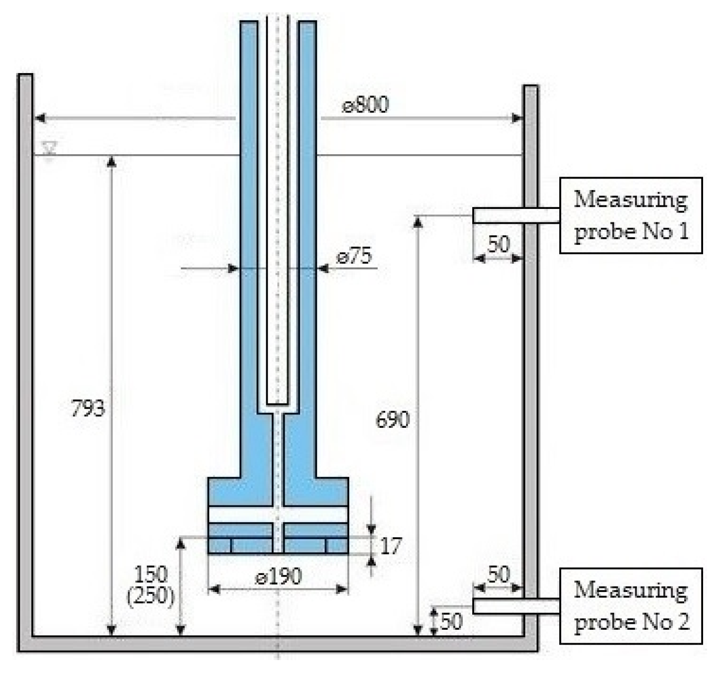
2. Experimental Conditions of Physical Modelling

Experiments investigating the degassing of the metal melt by inert gas in refining ladle were performed in the Laboratory of Physical and Numerical Modelling at the Department of Metallurgy and Foundry, FMT (Faculty of Materials Science and Technology), of the VŠB—Technical University of Ostrava. The physical model was made of transparent organic glass (plexiglass) in a 1:1 scale to the real equipment (prototype) for the refining of molten aluminum with a ladle inner diameter of 800 mm. Additionally, two graphite baffles for suppressing excessive surface ripple and vortex formation were included in the physical modelling. Figure 1 and Figure 2, above, show a physical model assembly. Figure 3 shows the basic dimensional data of the physical model, including the location of the measuring probes.
Five variants of impellers, referred to as F2A 190, F2A-Z 190, J8 190, J8-Z 190, and J8-ZD 190, were used for modelling (see Figure 4). These impellers were supplied by JAP INDUSTRIES, s.r.o.
The impeller F2A 190 has side and lower exhaust of blown gas, F2A-Z 190 has only a side exhaust of blown gas—between the side protrusions. The impeller J8 190 has a lower single-hole gas exhaust, the impeller J8-Z 190 also has lower exhaust, but in a configuration of eight smaller holes between the individual ribs while the impeller J8-ZD 190 has these exhaust holes in the side wall of the central cylindrical part.
The change of the impeller immersion was solved by a hydraulically controlled platform, on which the physical model of the ladle was placed. Rotary impeller speeds (revolutions per minute; rpm) were controlled by using an asynchronous motor, which was powered by alternating current with variable frequency from an inverter. The model also included pressure bottles with oxygen and argon. Needle regulate valves, three-way valve, and mass flowmeters were used to measure and regulate the flow of gases—oxygen and argon [1].
The decrease of hydrogen content in molten aluminium during refining with inert gas is simulated at physical modelling by a decrease of dissolved oxygen in model liquid (water). The main advantage of using water is primarily its low cost, good availability, and especially because of the fact that it has similar physical properties as liquid aluminium. The dynamic and kinematic viscosity of aluminium and water can be considered to be very close. Table 1 shows a comparison of the basic parameters of aluminium and water.
Laboratory experiments were conducted in accordance with the theory of similarity between the model and the prototype, based on the identity of Froude’s criterion. It is necessary to observe, in particular, geometrical similarity of the prototype and its model, and the dynamic similarity of fluid in prototype and in its model. Before each experiment, water was saturated with gaseous oxygen to the value of 23 ppm (23 mg O2·l−1 of water) through the rotating impeller. The actual experiment started with exact rotary impeller speeds and flow rate of argon. Two optical fluorescent probes were used for the continuous measurement of oxygen content in the model bath (water). These probes were capable of recording dissolved oxygen content up to 26 ppm.
During the rotating and blowing of inert gas, there is an intense formation of gas–liquid mixture with very fine bubbles, which increases the refining efficiency.
Under normal operating conditions, baffles are commonly used to prevent dangerous surface ripple and vortex formation. For this reason, two baffles were used on the physical model during the experiments.
The main aim of physical modelling was to achieve insight into the effect of relevant parameters (see Table 2) on the removal of dissolved oxygen during refining. The research concentrated on:
  • rotary impeller speeds,
  • flow rate of inert gas,
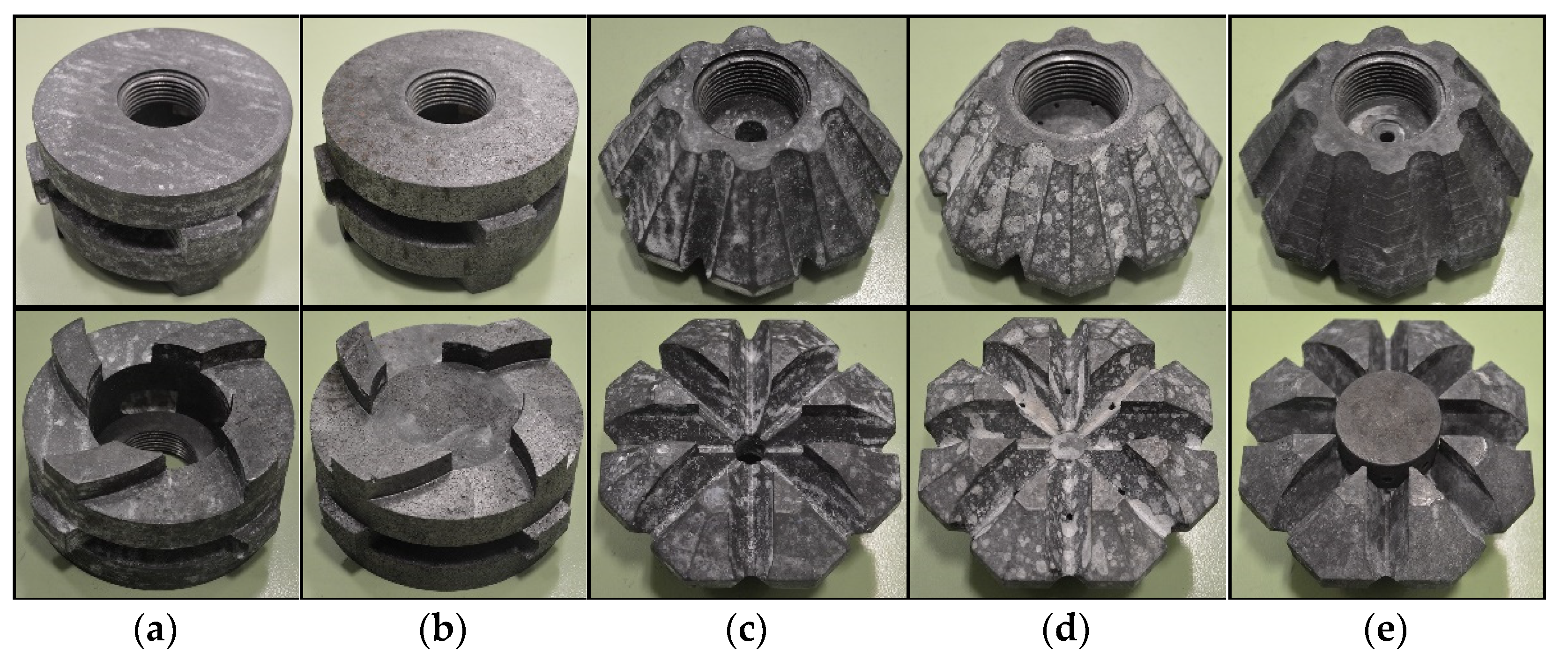
  • impeller variant, and
  • distance of the impeller from the bottom of the refining ladle.

3. Results and Discussion

The evaluation of the experiments was carried out in three phases. In the first phase, results were compared by the use of combined graphs, in the second phase, the results were compared on the basis of the requirements for reaching a dimensionless concentration in the bath (in this case, 0.5 and 0.1) and, in the last evaluation phase, visualization photos were taken, where the size of bubbles and the distribution of these bubbles into the volume of the refining ladle were studied.

3.1. The Comparison of Experiments by Use of Combined Graphs

Combined graphs present the time dependence of the oxygen concentration changes during refining by inert gas. Two optical fluorescent probes were used to measure the dissolved oxygen concentration in water (A1—upper probe, A2—lower probe), as already mentioned. The analysis of the results revealed that the course of change in the oxygen concentration indicated by these probes is practically identical. This behaviour was evident in all experiments, due to the high rate of turbulence, which caused an almost homogeneous concentration field across the entire refining ladle model volume. Values from the lower probe A2 were used at the next evaluation due to this behaviour.

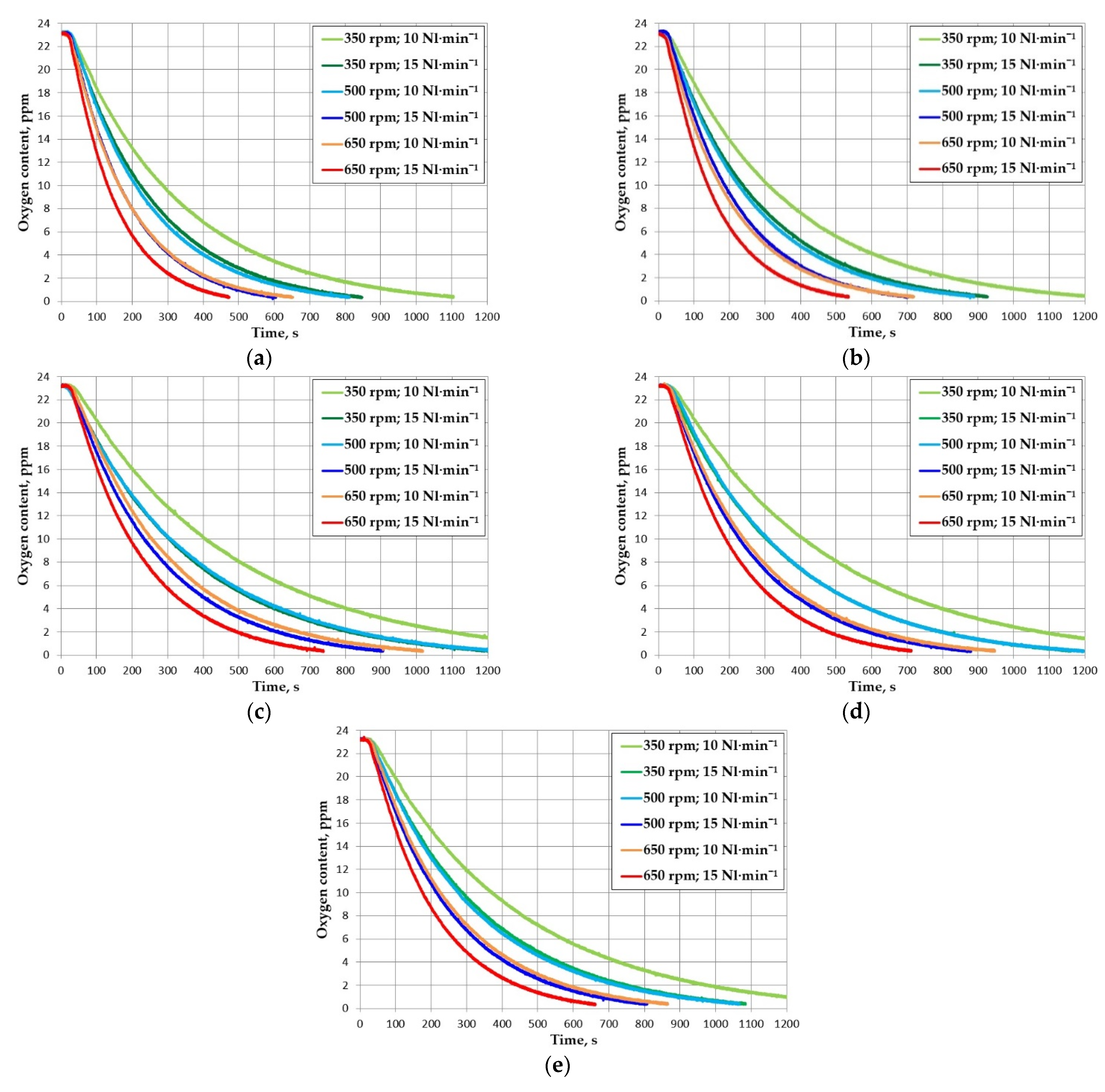
3.1.1. The Influence of Rotary Impeller Speeds and Flow Rate of Inert Gas for the Individual Impellers

The influence of rotary impeller speeds and flow rate of inert gas was monitored for 350, 500, and 650 rpm values at a constant flow rate of inert gas of 10 and 15 Nl·min−1 and the distance of the impeller from the bottom of the ladle of 150 mm. Figure 5 shows the graphs with the results of the individual impellers F2A 190, F2A-Z 190, J8 190, J8-Z 190, and J8-ZD 190.
From the graphs that are shown below, a significant effect of increased rotary impeller speeds on the process of reduction of oxygen content is demonstrated. The increased flow rate of inert gas also has an influence. The dependence on gas rate can be seen in the different steepness of curves at the same rotary speed.
The graphs show that it is possible to trace a simple connection between an increase in rotary speeds and the flow rate of inert gas. The same positive effect as the increase rotary speeds by 150 rpm can also be approximately achieved by increasing the flow rate of inert gas from 10 to 15 Nl·min−1 without changing the rotary speeds. It follows that the highest efficiency was achieved at a rotary speed of 650 rpm and a flow rate of inert gas of 15 Nl·min−1.
The comparison of individual graphs shows that the impeller F2A-Z 190 achieved worse results than the impeller F2A 190. For the J8 variant impellers, the plots show that the impeller J8-Z 190 achieved similar results and the impeller J8-ZD 190 had significantly better results when compared to the impeller J8 190.

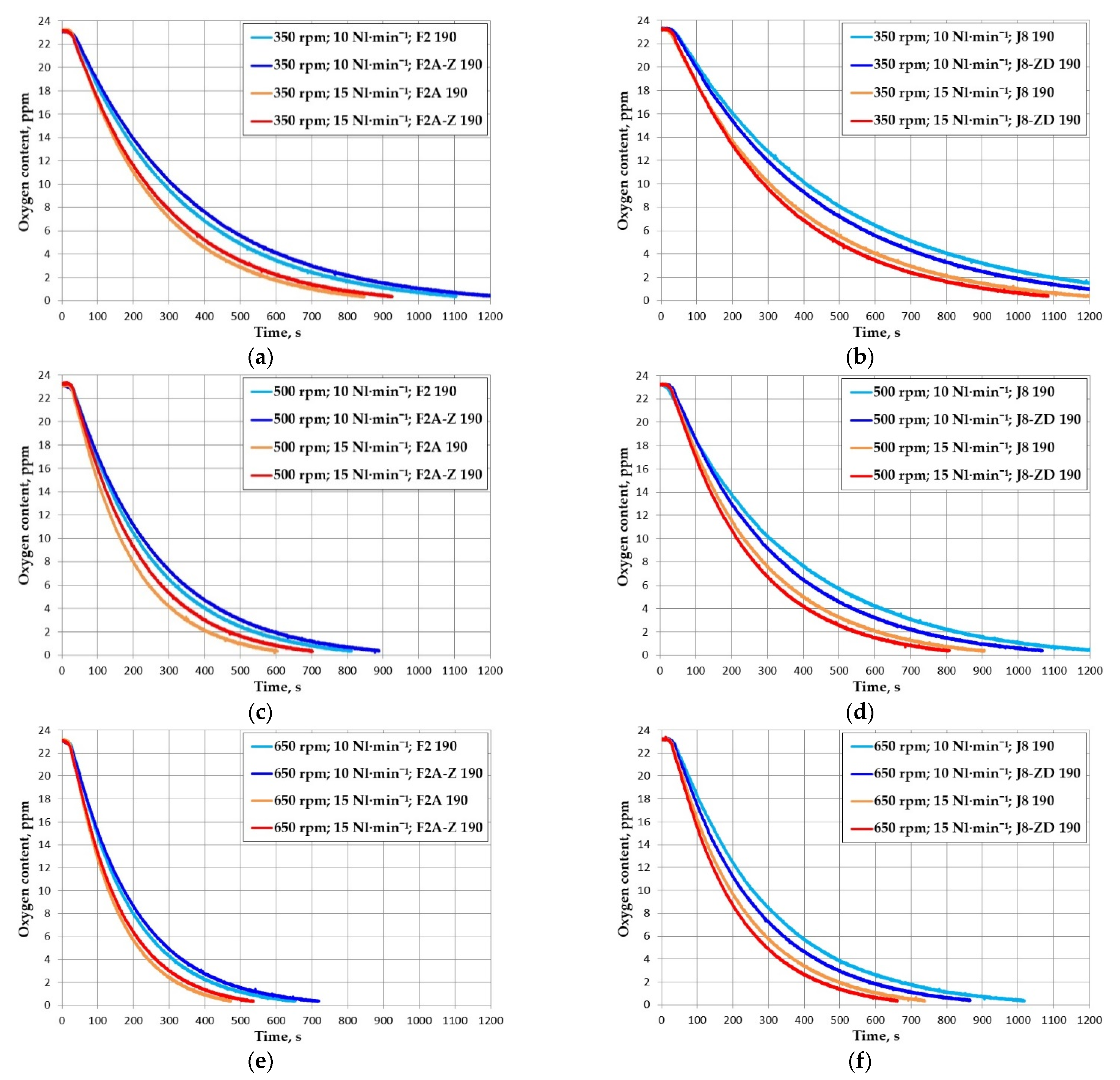
3.1.2. The Comparison of Individual Impellers

This part deals with the comparison of impellers F2A 190 and F2A-Z 190 and impellers J8 190 and J8-ZD 190 at rotary speeds 350, 500, and 650 rpm at a constant flow rate of inert gas of 10 and 15 Nl·min−1 and the distance of the impeller from the bottom of the ladle 150 mm (see Figure 6).
The comparison of graphs shows that the impeller F2A-Z 190 achieved worse results than the impeller F2A 190 under all of the experimental conditions. This is mainly due to the geometry of the impeller, which caused the effect to be lower in this embodiment of the impeller. This may be related to the poorer distribution of argon bubbles to the bath, and a consequent reduction in the effect of refining process under the impeller itself, where, in the case of the impeller F2A-Z 190, the occurrence of bubbles was lower. The graphs also show that the impeller J8-ZD 190 achieved better results when compared to the impeller J8 190. The geometry of the impeller J8-ZD 190 causes a more even distribution of the bubbles of the blown inert gas, which were additionally dispersed into very fine bubbles by the lower ribs of the impeller, which had a positive effect on the better refining effect of this impeller.

3.1.3. Effect of Impeller Distance from the Ladle Bottom

The distance of the impeller from the bottom of the ladle has a very important effect on the promotion of an even distribution of inert gas in the volume of the refined bath. At a greater distance from the bottom, the effect of refining may be less pronounced; at a shorter distance from the bottom, there may be a risk of increased lining erosion due to excessive turbulence and rotation of the bath near the bottom of the ladle.
Figure 7 shows graphs documenting the effect of the distance between the impeller and the bottom of the model for 150 and 250 mm, at a rotary speeds of 500 rpm and a flow rate of inert gas of 10 and 15 Nl·min−1, for impellers F2A 190, J8 190, and J8-ZD 190.
The graphs presented below clearly show that the increase in the distance of the impeller from the bottom of the ladle from 150 to 250 mm was reflected in a decrease in refining efficiency, respectively, in increasing refining times. A similar course was confirmed at a rotary speeds 350 and 500 rpm.

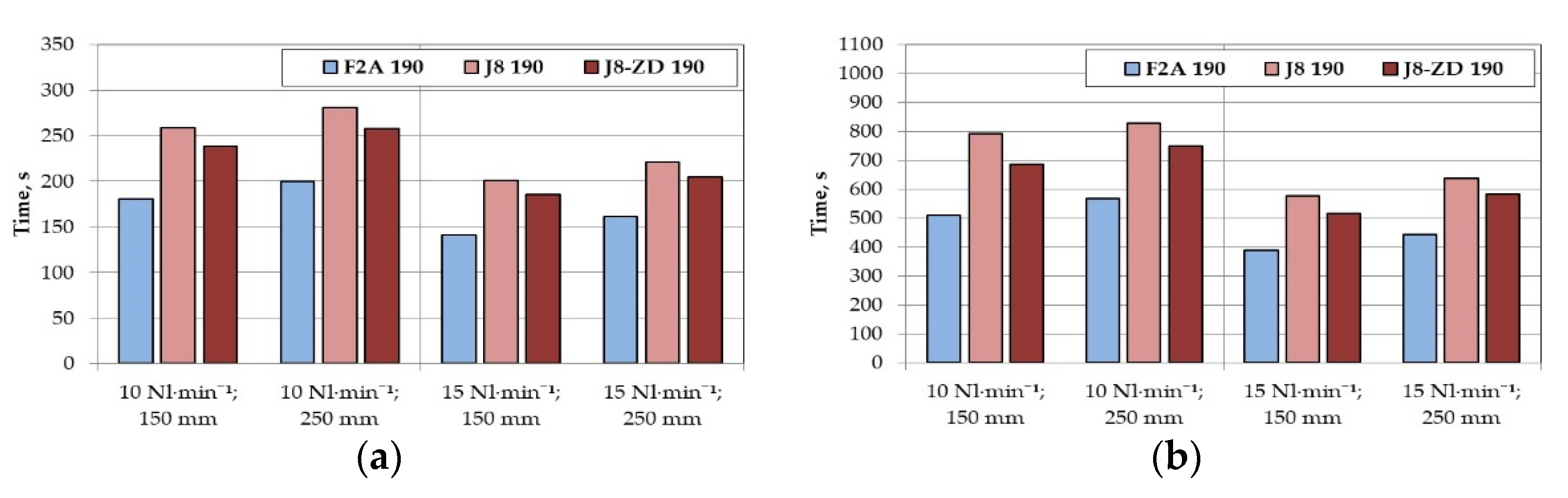
3.2. Comparison of the Results Based on the Time to Reach the Dimensionless Concentration

For an easier interpretation and graphical comparison of the achieved results of the given experiments, the times τ0.5 and τ0.1 are compared. These times represent times under which the initial oxygen concentration in the bath was reduced at 50% and 10%, respectively, in other words, in which dimensionless concentrations Cx = 0.5 and Cx = 0.1 were achieved. The dimensionless concentration Cx is calculated, according to Equation (1):
Cx = Cτ/Cint
where
Cτ  oxygen concetration in the bath (ppm)
Cint  initial concentration at beginning of the experiment (standardized to 23 ppm)
The time τ0.5 and τ0.1 is the time during which the original concentration of 23 ppm drops to 11.5 ppm and analogously to 2.3 ppm. Therefore, these parameters can characterise the rate of reduction of content of oxygen dissolved in the bath.
The above comparison was made in summary for the main monitored parameters:
  • rotary impeller speeds, volume flow rate of inert gas, and impeller geometry, and
  • distance of the impeller from the bottom of the ladle.

3.2.1. Influence of Rotary Impeller Speeds, Volume Flow Rate of Inert Gas and Impeller Geometry

Figure 8 shows the significant effect of rotary speeds and volume flow rate of inert gas on both values τ0.5 (a) a τ0.1 (b). As the rotary speeds (350, 500, 650 rpm) and flow rate (10, 15 Nl·min−1) increase, both τ0.5 and τ0.1 decrease. Again, there is a clearly visible trend, in which approximately the same positive effect as an increase in rotary speeds of 150 rpm at a constant flow rate can be achieved by increasing the flow rate of inert gas from 10 to 15 Nl·min−1 without changing the rotary speeds.
From both of the graphs, it is also clear that the best results were achieved by the impeller F2A 190. Its modification F2A-Z 190 showed worse results. The results of using the impeller J8 190 indicate that its refining efficiency is the worst of the compared impellers; the modification J8-ZD 190 brought a positive effect as compared to the J8 190; however, even this modified type does not achieve the results of the impeller F2A 190.

3.2.2. Influence of the Distance of the Impeller from the Bottom of the Ladle

The increase in the distance of the impeller from the bottom of the ladle from 150 to 250 mm (see Figure 9) was reflected in an increase in the values of τ0.5 a τ0.1 under all conditions of experimental and for all impellers used. However, these increases are not so significant to significantly extend the total time of refining.
The obtained experimental data were checked, and it can be said that the curves correspond to the exponential dependence of c = co.ekt with an exponent in the range of −0.003 to −0.009. It can also be seen from the columnar graphs that the time τ0.1 is three times higher than the time τ0.5 in most of the variants.

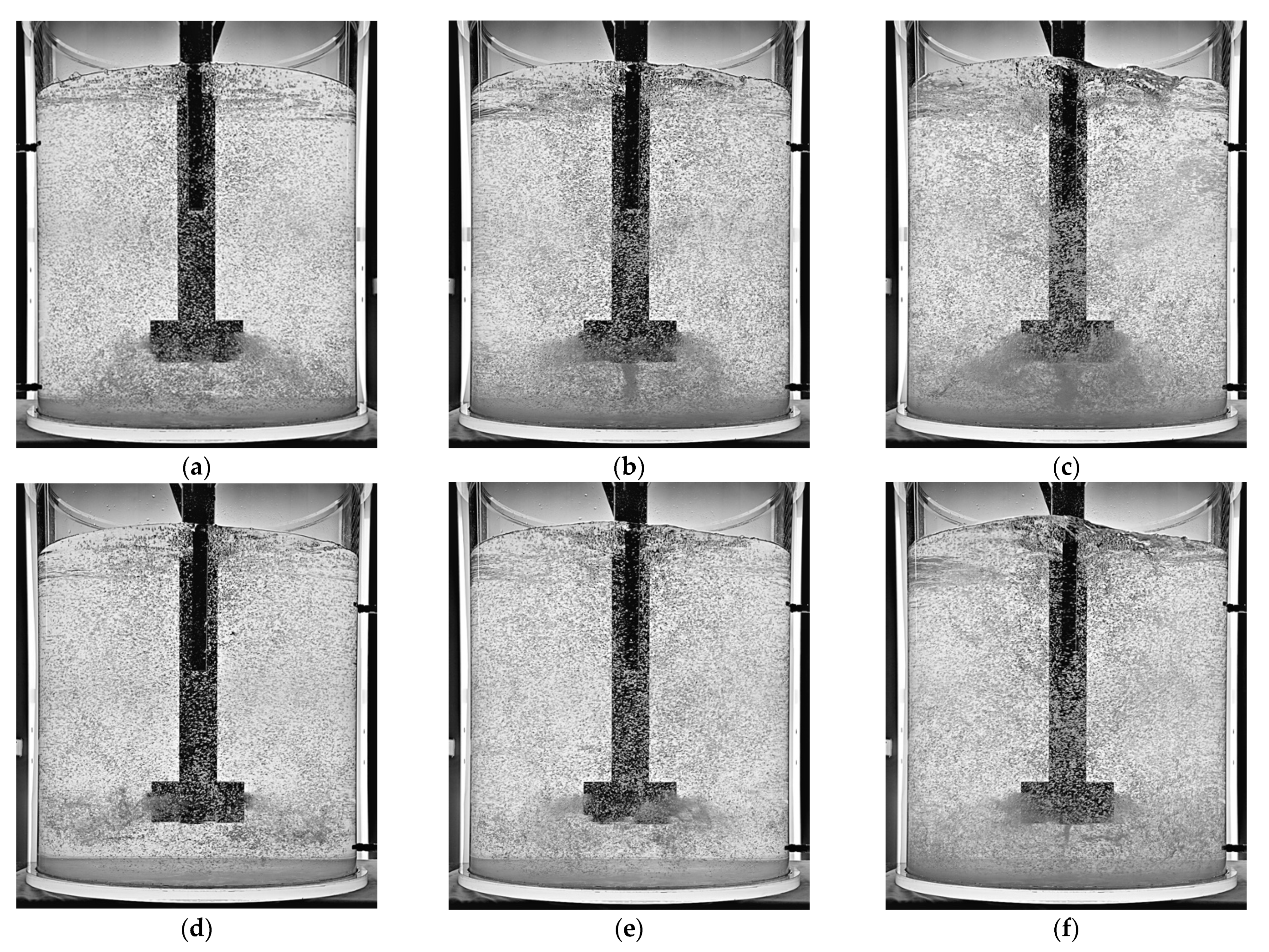
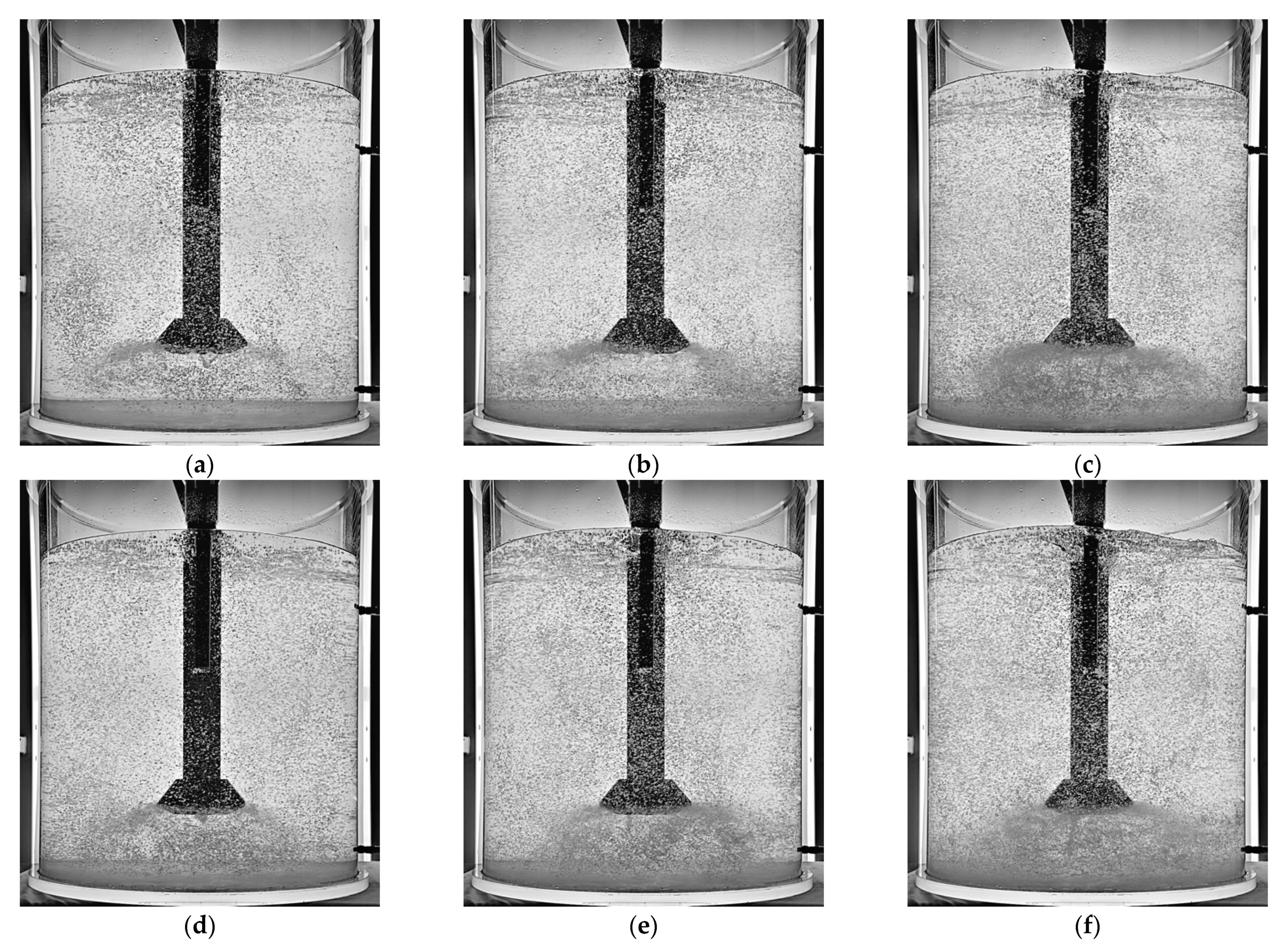
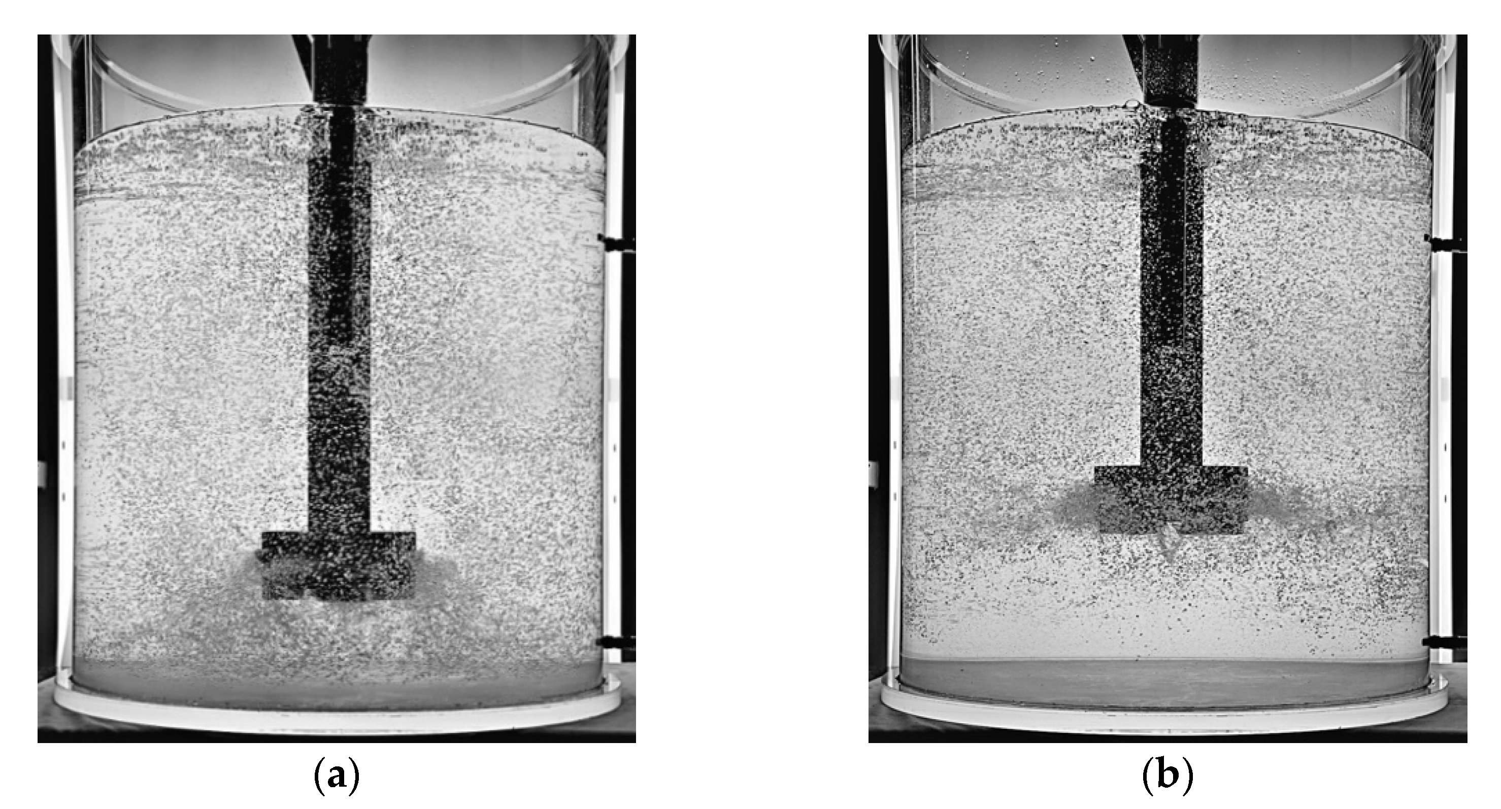
3.3. Visualization Monitoring

During the experiments, photos of the bath behaviour inside the model were taken, from which the fluid flow and the amount and distribution of inert gas bubbles could be evaluated. The impellers F2A 190, F2A-Z 190, J8 190, and J8-ZD 190 were used for visualisation, at rotary speeds of 350, 500, and 650 rpm and a volume flow rate of inert gas of 10 and 15 Nl·min−1.
Figure 10 and Figure 11 show the selection of the bath behaviour using the above-mentioned impellers and a volume flow rate of inert gas of 10 Nl·min−1 at the distance of the impeller from the bottom of 150 mm.
In these photos, the effect of increasing rotary speeds that range from 350 to 650 rpm is evident, with the more intense distribution of bubbles throughout the refining ladle volume, as well as a higher level of bath surface ripple in the refining ladle.
With the impeller F2A 190, intense swirling and increased bubble concentration can be observed not only on the sides of the impeller, but also below it, especially at higher rotary speeds. The formation of an intense vortex is also visible under the impeller, and in regular cycles also large rotating cavities that are filled with inert gas. These cavities break at about three-second intervals and then divide into a large number of small bubbles.
From the photos, it is clear that the rotation of liquid also exists under the impeller F2A-Z 190, but the formation of the cavity is less intense, the concentration of bubbles under the impeller is lower as compared to the impeller F2A 190. This behaviour apparently related the impeller F2A-Z 190 to be less efficient than the impeller F2A 190.
With the impeller J8 190, we can also observe the formation of cavities that are filled with inert gas, even at low rotary speeds of 350 rpm. If the size of the rotating cavity exceeds the critical size, the cavity will break to form a large number of small bubbles.
The design of the impeller J8-ZD 190 was based on the requirement to limit the formation of these cavities under the impeller. Indeed, the behaviour of the bath during refining confirmed a lower occurrence of cavities, which only formed at a higher rotary speeds of 650 rpm and in even smaller volumes. The better distribution of inert gas bubbles in the space of the refining ladle also led to a better efficiency of this impeller when compared to the impeller J8 190.
Attention was also paid in the visualisation experiments to the influence of the distance of the impeller from the bottom of the refining ladle (see Figure 12). The evaluation of the course of the dissolved oxygen content showed that the increase of this distance from 150 to 250 mm was reflected in a decrease in the efficiency of refining, respectively, in increasing refining times.
A possible explanation can be, as follows. At low rotary speeds, large bubbles form, which arise in the immediate vicinity of the impeller and then float to the surface. By shifting the point of formation of these bubbles by another 100 mm upwards, the volume of melt that is able to react with the bubbles of inert gas is reduced, which leads to a reduction in the efficiency of refining. At increased rotary impeller speeds, which lead to increased melt turbulence and vortex formation, this difference in efficiency decreases.

4. Conclusions

Degassing (a reduction of hydrogen content) in aluminium-based melts was simulated in physical modelling by the process of reducing the dissolved oxygen content in water at a temperature of 20 °C. Its concentration in the water bath was measured while using two fluorescent probes.
The experiments were conducted under laboratory experiments in order to determine and evaluate the effect of each parameter on the efficiency of the melt refining process. The ability to influence the efficiency of the process was compared for individual parameters. These parameters include the rotary impeller speed, the volume flow rate of inert gas, the height of the impeller above the bottom of the ladle, and the geometry of the impeller.
The evaluation of the experiments was carried out in three phases. In the first phase, experiments were performed, which were focused on the influence of individual parameters on the behaviour of oxygen during refining, which were then used to create combined graphs. In the second phase, the results were compared on the basis of the time to reach the dimensionless concentration of 0.5 and 0.1 in the bath. In the last phase, visualisation photos were taken, where the size of the bubbles and the arrangement of these bubbles in the volume of the refining ladle were examined.
Based on the results that were obtained from experimental measurements, the following findings can be formulated:
  • The rotary impeller speed has a very significant effect on the efficiency of the whole bath degassing process. The increased flow rate of inert gas also has an influence.
  • Approximately the same positive effect as the increase rotary speeds by 150 rpm can also be achieved by increasing the flow rate of inert gas from 10 to 15 Nl·min−1 without changing the rotary speeds.
  • The comparison of impellers F2A 190 and F2A-Z 190 shows that the impeller F2A-Z 190 achieved worse results than the impeller F2A 190 under all of the experimental conditions. This is mainly due to the geometry of the impeller.
  • The impeller J8-ZD 190 achieved better results when compared to the impeller J8 190. The geometry of the impeller J8-ZD 190 causes a more even distribution of the bubbles of the blown inert gas, which were additionally dispersed into very fine bubbles by the lower ribs of the impeller.
  • The results clearly show that the increase in the distance of the impeller from the bottom of the ladle from 150 to 250 mm was reflected in a decrease in refining efficiency, respectively, in increasing refining times.
  • The comparison of values τ0.5 a τ0.1, ie. times during which the oxygen concentration in the bath was decreased to 50% resp. 10% of the initial value, led to the conclusion that the best results were achieved by the impeller type F2A 190.
  • During the experiments, photos of the bath behaviour inside the model were taken. The effect of increasing rotary speeds that range from 350 to 650 rpm is evident, with the more intense distribution of bubbles throughout the refining ladle volume.

Author Contributions

Methodology, J.W., K.M., M.T. and M.S.; modelling, J.W., K.M. and M.T.; writing—original draft, J.W., K.M. and M.T.; writing—review and editing, J.W., K.M. and M.T. All authors have read and agreed to the published version of the manuscript.

Funding

This research was funded with the support of the Czech Ministry of Industry and Trade within the frame of the programme TRIO within the solution of the project reg. No. FV10080 “Research and Development of Advanced Refining Technologies of Aluminium Melts for Increase in Product Quality”. The article was created thanks to the project No. CZ.02.1.01/0.0/0.0/17_049/0008399 from the EU and CR financial funds provided by the Operational Programme Research, Development and Education, Call 02_17_049 Long-Term Intersectoral Cooperation for ITI, Managing Authority: Czech Republic-Ministry of Education, Youth and Sports. This work was also supported by the Student Grant Competition No. SP2020/64 and SP2020/39.

Conflicts of Interest

The authors declare no conflict of interest. The funders had no role in the design of the study; in the collection, analyses, or interpretation of data; in the writing of the manuscript; or in the decision to publish the results.

References

  1. Michalek, K.; Tkadlečková, M.; Socha, L.; Gryc, K.; Saternus, M.; Pieprzyca, J.; Merder, T. Physical Modelling of Degassing Process by Blowing of Inert Gas. Arch. Metall. Mater. 2018, 63, 987–992. [Google Scholar] [CrossRef]
  2. Hernández-Hernández, M.; Camacho-Martínez, J.; González-Rivera, C.; Ramírez-Argáez, M.A. Impeller design assisted by physical modeling and pilot plant trials. J. Mater. Process. Technol. 2016, 236, 1–8. [Google Scholar] [CrossRef]
  3. Saternus, M. Rafinacja Aluminium i Jego Stopów przez Przedmuchiwanie Argonem; Wydawnictwo Politechniky Ślaskej: Gliwice, Poland, 2011; p. 167. ISBN 978-83-7335-892-8. (In Polish) [Google Scholar]
  4. Wang, L.; Guo, E.; Huang, Y.; Lu, B. Rotary impeller refinement of 7075Al alloy. Rare Met. 2009, 28, 309–312. [Google Scholar] [CrossRef]
  5. Mostafaei, M.; Ghobadi, M.; Eisaabadi, G.B.; Uludağ, M.; Tiryakioğlu, M. Evaluation of the Effects of Rotary Degassing Process Variables on the Quality of A357 Aluminum Alloy Castings. Met. Mater. Trans. A 2016, 47, 3469–3475. [Google Scholar] [CrossRef]
  6. Merder, T.; Saternus, M.; Warzecha, P. Possibilities of 3D Model Application in the Process of Aluminium Refining in the Unit with Rotary Impeller. Arch. Met. Mater. 2014, 59, 789–794. [Google Scholar] [CrossRef] [Green Version]
  7. Saternus, M.; Merder, T.; Pieprzyca, J. The Influence of Impeller Geometry on the Gas Bubbles Dispersion in Uro-200 Reactor—RTD Curves/Wpływ Rodzaju Wirnika Na Dyspersję Pęcherzyków Gazowych W Reaktorze URO-200—Krzywe Mieszania. Arch. Met. Mater. 2015, 60, 2887–2894. [Google Scholar] [CrossRef]
  8. Yamamoto, T.; Suzuki, A.; Komarov, S.V.; Ishiwata, Y. Investigation of impeller design and flow structures in mechanical stirring of molten aluminum. J. Mater. Process. Technol. 2018, 261, 164–172. [Google Scholar] [CrossRef]
  9. Gao, G.; Wang, M.; Shi, D.; Kang, Y. Simulation of Bubble Behavior in a Water Physical Model of an Aluminum Degassing Ladle Unit Employing Compound Technique of Rotary Blowing and Ultrasonic. Met. Mater. Trans. A 2019, 50, 1997–2005. [Google Scholar] [CrossRef]
  10. Camacho-Martínez, J.L.; Ramírez-Argáez, M.A.; Zenit, R.; Juárez-Hernández, A.; Barceinas-Sánchez, J.; Trápaga-Martínez, G.; Trápaga-Martínez, G. Physical Modelling of an Aluminium Degassing Operation with Rotating Impellers—A Comparative Hydrodynamic Analysis. Mater. Manuf. Process. 2010, 25, 581–591. [Google Scholar] [CrossRef]
  11. Yu, S.; Zou, Z.; Shao, L.; Louhenkilpi, S. A Theoretical Scaling Equation for Designing Physical Modeling of Gas-Liquid Flow in Metallurgical Ladles. Steel Res. Int. 2016, 88, 1600156. [Google Scholar] [CrossRef]
  12. Abreu-López, D.; Dutta, A.; Camacho-Martínez, J.L.; Trápaga-Martínez, G.; Ramírez-Argáez, M.A. Mass Transfer Study of a Batch Aluminum Degassing Ladle with Multiple Designs of Rotating Impellers. JOM 2018, 70, 2958–2967. [Google Scholar] [CrossRef]
  13. Mancilla, E.; Cruz-Méndez, W.; Garduño, I.E.; González-Rivera, C.; Ramírez-Argáez, M.A.; Ascanio, G. Comparison of the hydrodynamic performance of rotor-injector devices in a water physical model of an aluminum degassing ladle. Chem. Eng. Res. Des. 2017, 118, 158–169. [Google Scholar] [CrossRef]
  14. Michalek, K. Využití Fyzikálního a Numerického Modelování pro Optimalizaci Metalurgických Procesů; VŠB-Technická Univerzita Ostrava: Ostrava, Czech Republic, 2001; p. 125. ISBN 80-7078-861-5. (in Czech) [Google Scholar]
  15. Saternus, M.; Merder, T. Physical Modelling of Aluminum Refining Process Conducted in Batch Reactor with Rotary Impeller. Metals 2018, 8, 726. [Google Scholar] [CrossRef] [Green Version]
  16. Hu, Z.C.; Zhang, E.L.; Zeng, S.Y. Degassing of magnesium alloy by rotating impeller degasser: Part 1—Mathematical modelling. Mater. Sci. Technol. 2008, 24, 1304–1308. [Google Scholar] [CrossRef]
  17. Zhang, E.; Wang, G.J.; Hu, Z.C. Degassing of magnesium alloy by rotating impeller degasser Part 2—Effect on microstructure and mechanical properties. Mater. Sci. Technol. 2010, 26, 1253–1258. [Google Scholar] [CrossRef]
  18. Juarez, R.; Flores, A.; Macías, E.; Reyes, N. Análisis del comportamiento de flujo de fluidos en un horno de reverbero agitado con diferentes impulsores, mediante la modelación física y numérica. Rev. Met. 2009, 45, 384–396. [Google Scholar] [CrossRef]
Figure 1. View of the physical model assembly with accessories.
Metals 11 00284 g001
Figure 2. Physical model of a refining ladle with an impeller and two baffles.
Metals 11 00284 g002
Figure 3. Basic dimensional data of physical model with the impeller F2A 190.
Metals 11 00284 g003
Figure 4. The impellers used for modelling: (a) F2A 190; (b) F2A-Z 190; (c) J8 190; (d) J8-Z 190; and, (e) J8-ZD 190.
Metals 11 00284 g004
Figure 5. Influence change of rotary impeller speeds an flow rate of inert gas for the individual impellers: (a) F2A 190; (b) F2A-Z 190; (c) J8 190; (d) J8-Z 190; and, (e) J8-ZD 190.
Metals 11 00284 g005
Figure 6. Comparison of individual impellers: (a,c,e) F2A 190 and F2A-Z 190; (b,d,f) J8 190 and J8-ZD 190.
Metals 11 00284 g006
Figure 7. Influence of the distance of the impeller above the bottom of the ladle for the impellers: (a) F2A 190; (b) J8 190; and, (c) J8-ZD 190.
Metals 11 00284 g007
Figure 8. Comparison of the influence of rotary speeds, volume flow rate of inert gas and impeller geometry at a constant distance of the impeller from the bottom of 150 mm on the values: (a) τ0.5; (b) τ0.1.
Metals 11 00284 g008
Figure 9. Comparison of the influence of the distance of the impeller from the bottom of the ladle at the volume flow rate of inert gas 10 and 15 Nl·min−1 on the values: (a) τ0.5; (b) τ0.1.
Metals 11 00284 g009
Figure 10. Visual images of the flow of gas in the bath at the volume flow rate of inert gas of 10 Nl·min−1: (a) F2A 190–350 rpm; (b) F2A 190–500 rpm; (c) F2A 190–650 rpm; (d) F2A-Z 190–350 rpm; (e) F2A-Z 190–500 rpm; and, (f) F2A-Z 190–650 rpm.
Metals 11 00284 g010
Figure 11. Visual images of the flow of gas in the bath at the volume flow rate of inert gas of 10 Nl·min−1: (a) J8 190–350 rpm; (b) J8 190–500 rpm; (c) J8 190–650 rpm; (d) J8-ZD 190–350 rpm; (e) J8-ZD 190–500 rpm; and, (f) J8-ZD 190–650 rpm.
Metals 11 00284 g011
Figure 12. Comparison of the bath behaviour in the ladle under the same conditions at the distance of the impeller from the bottom of the ladle: (a) 150 mm; (b) 250 mm.
Metals 11 00284 g012
Table 1. Comparison of basic physical parameters of the aluminium melt and water [1,14].
ParameterAluminiumWater
Temperature—T (K)1023293
Density—ρ (kg·m−3)2345998.5
Dynamic viscosity—η (kg·m−1·s−1)0.001200.00101
Kinematic viscosity—ν (m2·s−1)0.51 × 10−61.012 × 10−6
Surface tension—σ (N·m−1)0.6800.072
Table 2. Overview of experimental conditions for physical modelling of refining process in the ladle.
Impeller VariantF2A 190F2A-Z 190J8 190J8-Z 190J8-ZD 190
Distance of the impeller (mm)150150150150150
250250250
Volume flow rate of Ar (Nl·min−1)1010101010
1515151515
Rotary impeller speeds (rpm)350350350350350
500500500500500
650650650650650
Publisher’s Note: MDPI stays neutral with regard to jurisdictional claims in published maps and institutional affiliations.

