1. Introduction
Laser Powder Bed Fusion (PBF-LB/M) is currently the most widely used process for additive manufacturing of metals [
1] and is gaining an increasing importance in industry and science alike [
2]. Potential applications are high-value components in the aerospace industry, like fuel nozzles [
3] or further engine parts [
4], motor sport components [
5], tool inserts with internal cooling channels [
6], or medical implants [
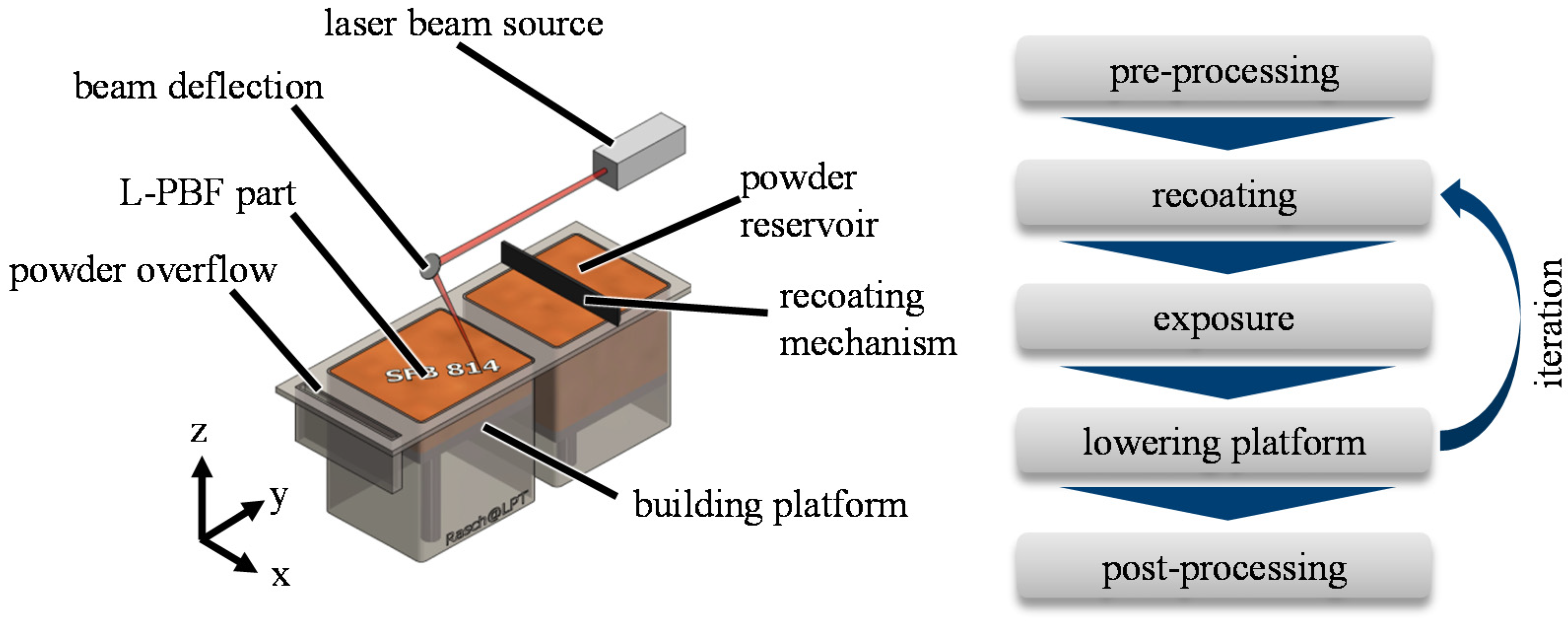
7]. The basic process principle is shown in
Figure 1. Major advantages are an almost unlimited degree of design-freedom and a high flexibility of the production process. The achievable material properties are close to or even superior to conventional manufacturing [
8]. However, one important drawback of PBF-LB/M, that is restricting the application of the process, is the limited variety of qualified materials. While thousands of different metal alloys are available, only a few dozens of them have been qualified for PBF-LB/M [
8]. With only very few exceptions (e.g., Scalmalloy [
9]), most of the alloys that are currently in use for PBF-LB/M have been originally designed for conventional manufacturing processes, like casting. However, the PBF-LB/M process is characterized by unique thermo-mechanical conditions, like high cooling rates in the range of 10
6 K/s [
10] and a cyclic re-heating during melting of consecutive scan tracks and layers. Especially the high cooling rates open up possibilities for developing and processing novel alloy classes, like bulk metallic glasses [
11] or compositionally complex alloys or high entropy alloys, respectively [
12]. However, the range of possible alloy compositions is vast and the availability of pre-alloyed powder is limited. The atomization of special alloys on request is possible but is expensive and time consuming, which is effectively slowing material development for PBF-LB/M. One possibility to ease material development for PBF-LB/M and facilitate high throughput investigations of novel alloy compositions is in-situ alloy formation. By using mixtures of easily available standard powders, an expensive and time-consuming atomization of pre-alloyed powder can be avoided. However, achieving a homogeneous element distribution and a complete dissolution of the powder particles during PBF-LB/M is challenging. This is especially true if the melting point of the added elements is far above the melting point of the main alloying element.
Aota et al. [
14] investigated in-situ alloy formation of 1.4307 (AISI 304L) from elemental Fe, Ni and Cr powder. They achieved a homogeneous element distribution for certain parameter combinations and concluded that the dwell time of the particles in the meltpool is crucial for achieving a complete dissolution of the particles. In addition, Chen at al. [
15] obtained a fairly homogeneous element distribution by in-situ formation of a compositionally complex CoCrFeMnNi alloy. Their results show that a high volumetric energy input is favorable for in-situ alloy formation by PBF-LB/M. In contrast to these successful applications, in-situ alloy formation of Ti-based alloys proved to be more challenging. Yadroitsev et al. [
16] investigated in-situ formation of Ti15Mo and Ti1.38Cu alloys. While the lower melting Cu-particles (melting point 1084 °C [
17]) were completely fused, at least some of the higher melting Mo-particles (melting point 2623 °C [
17]) remained undissolved. Despite the complete melting of the Cu-particles, Yadroitsev et al. [
16] also report areas with increased copper content, mainly located at the fusion boundaries of consecutive melt tracks. Mosallanejad et al. [
18] made similar observations in in-situ alloyed Ti5Cu samples. They also describe segregation of Cu at fusion boundaries an in addition to Yadroitsev et al. [
16] also some remaining unmolten Ti-particles. Grigoriev et al. [
19] investigated synthesis of Ti5Al and a Ti22Al25Nb alloys by in-situ alloy formation. They showed that PBF-LB/M with a 700 µm laser spot diameter and 950 W laser power results in a homogeneous material. Using a configuration with 70 µm beam diameter resulted in undissolved Al-particles in the Ti matrix. The Ti22Al25Nb alloy processed with the 700 µm laser spot contained unmolten Nb particles that could be removed by a heat-treatment at 1250 °C for 2 h. Polozov et al. [
20] achieved similar results as Yadroitsev et al. [
16] with undissolved Nb particles in Ti6Al7Nb and Ti22Al25Nb alloys that could be removed by annealing at 1250 °C and 1350 °C, respectively. Fischer et al. [
21] prepared an Ti26Nb alloy by in-situ alloy formation. Their results show that the number of remaining Nb-particles is influenced by the PBF-LB/M parameter combination and that higher volumetric energy densities lead to a reduced number of remaining particles. Huang et al. [
22] and Dzogbewu [
23] investigated in-situ alloy formation of Ti with Ta and Mo, respectively. Both elements feature an even higher melting point than Nb, and dissolving the high melting particles proved to be challenging.
These publications show that in-situ alloy formation is an appealing and widely used method to ease material development for additive manufacturing of metals. However, despite some successful applications, e.g., for Fe-, Ni-, Cr-based alloys, defects, like an inhomogeneous element distribution and/or undissolved particles, are common. Comprehensive investigations of the interdependencies between PBF-LB/M process strategy, material/powder properties, and the resulting homogeneity of the in-situ alloyed material are currently lacking. Especially in-situ alloy formation of Ti-based alloys containing high melting elements, like Nb, Mo, or Ta, proves to be challenging and requires further investigation. The present work represents a first step in that direction.
In this context, the aim was to gain a deeper understanding of the effect of the PBF-LB/M parameters and different scan strategies on the fusion of high-melting W, Ta, Mo, and Nb particles in a Ti-matrix. For this purpose, the number of unmolten particles in PBF-LB/M is quantified in dependence of the laser power, the scan speed, the focus diameter, and the scan strategy (single and two different double exposure strategy). Based on these experiments and discussion with literature, processing strategies for successful in-situ alloy formation by PBF-LB/M with a high dissolution ratio of high melting particles are derived. It is shown that, by applying these strategies, the number of residual high melting particles can be reduced by at least a factor of ten compared to the most unfavorable PBF-LB/M parameter combination. For Mo and Nb particles, even a complete dissolution of the high melting particles was achieved.
2. Materials and Methods
Scanning electron microscopy (SEM) images of the six different powders used in this work are shown in
Figure 2. The index 45 indicates the nominal upper particle size limit in µm.
The particle shape is predominantly spherical. The plasma atomized W 45, Ta 45 and Mo 45 powder was obtained from Tekna (Sherbrooke, QC, Canada). The Ti 45 powder, which is also plasma atomized, was supplied by AP&C Advanced Powders and Coatings Inc. (Boisbriand, QC, Canada) and the argon atomized Nb 45 powder was provided by H.C. Starck Tantalum and Niobium GmbH (Goslar, Germany). The chemical purity of all powders was verified by energy-dispersive X-ray spectroscopy (EDS) and is higher than 99.8 % (metallic elements). The particle-size distribution of the powders was verified by laser diffraction measurements using a Mastersizer 3000 from Malvern Panalytical GmbH (Malvern, UK). The results are listed in
Table 1.
For the PBF-LB/M experiments, five powder mixtures from 90 vol.% Ti 45 with 10 vol.% of each of the additional elements were prepared. The powders were mixed for 1 h in a Turbula®-mixer from Willy A. Bachofen AG (Muttenz, Switzerland) and dried in a vacuum furnace at 120 °C for 4 h to remove any moisture that might reduce flowability or interfere with the PBF-LB/M process. This procedure was empirically developed over the past years. The recoatability of the powder mixtures was verified visually inside the PBF-LB/M machine with the aid of an illumination setup (small angle illumination). All powder mixtures can be recoated to homogeneous layers without visible defects.
The PBF-LB/M parameter sets used in the following were developed experimentally and are partially derived from previous work [
24]. The aim was to investigate the dissolution behavior of the high melting particles in a wide range and to ensure a relative density of more than 97%, despite the variation in chemical composition and parameter combination. The relative density >97% was verified in preliminary experiments by polished microsections. The experimental design comprises the manufacturing of three series of PBF-LB/M samples. Details are described in
Table 2. Considerations regarding meltpool geometry [
25,
26], powder movement [
27], and process dynamics [
28] that led to the three series of experiments are based on previous work and literature. The intention of series 1 is to identify the effect of standard PBF-LB/M process parameters on the dissolution of high melting particles, while keeping the volumetric energy density (VED, definition given, e.g., in reference [
29]) constant. The aim of series 2 was to investigate the effect of an increasing scan speed, while keeping the laser power constant. Furthermore, a parameter combination with comparably low laser power (66 W) and slow scan speeds was selected. According to literature, this results in a short meltpool tail [
26], less gas and particle movement [
28], and, due to the slow movement of the laser spot, a longer interaction time with the laser beam. It is assumed that this has a positive effect on the dissolution of the high melting particles in the meltpool. The main idea investigated with series 3 was that a double exposure can further reduce the number of unmolten particles. For this purpose, two different strategies were conceived. The first one comprises a straightforward double exposure, while the second strategy comprises a pre-melting step for powder fixation and the actual consolidation step for part generation. The hypothesis behind the second double exposure strategy is to prevent denudation [
27] and dragging of high melting particles into the solidifying meltpool tail during the actual consolidation exposure, which is assumed to be a possible source of unmolten particles.
All PBF-LB/M experiments were done using an Aconity mini PBF-LB/M machine from Aconity GmbH (Herzogenrath, Germany) that is equipped with a redPower QUBE fiber laser from SPI Lasers Ltd. (Southampton, UK) with a maximum beam power of 1 kW and a wavelength of 1080 nm and an AxialSCAN-30 scanner optics from Raylase GmbH (Wessling, Germany). The sample geometry is cubic with an edge length of 6 mm. The number of undissolved particles was determined by polished microsections and light microscopy (image section 2.25 mm × 1.69 mm; 3.8 mm
2). Due to the high sample number, automated image analysis with MATLAB
® was employed to detect and count the particles. While most samples have a high relative density of more than 99.5%, in dependence of the process parameters, some samples contain up to 5% defects, which could lead to misdetections. This is considered by a filter algorithm that excludes dark objects (voids) from the count. In addition, very small particles that are probably image artifacts, small defects, or dirt are not considered. This approach is visualized in
Figure 3 and verified for ten selected images by manual counting. Deviations between manual counting and automated image analysis are below 5% in all cases.
3. Results and Discussion
The complete data set that is discussed in the following section is provided in the
Appendix A section alongside this manuscript. Due to the high number of figures, only selected diagrams are shown here.
Aim of experiment series 1 (see
Table 2) was to investigate the dissolution behavior of high melting particles in a Ti-matrix in dependence of standard PBF-LB/M parameters at a constant volumetric energy of 55.6 J/mm
3. The results for W 45 and Nb 45 particles are presented in
Figure 4. These materials represent the highest and lowest melting particle materials investigated. Data regarding the remaining particle materials (Ta 45, Mo 45) are provided in
Appendix A.
A first and rather self-evident observation is the number of undissolved particles scales with the melting point of the particle material [
17] with W resulting in the highest and Nb resulting in the lowest number of undissolved particles. Despite the melting point, further interdependencies between the PBF-LB/M parameter and the number of remaining particles are evident, which are discussed in the following.
The highest number of undissolved particles (114/mm
2) was measured for W 45 at a laser spot diameter of 200 µm and a scan speed of 1200 mm/s. The relative amount of W determined by image analysis of the cross-section is 7.6 vol.%. This is slightly lower than the originally introduced 10 vol.% W but shows that only a small portion of W particles was dissolved during PBF-LB/M. In contrast to that, the slowest scan speed and the smallest spot diameter investigated resulted in 29 undissolved particles per mm
2 and, hence, a reduction by the factor four. At a constant volumetric energy, PBF-LB/M parameter combinations featuring a slow scan speed and a small spot diameter appear to be beneficial for particle dissolution. This correlation is also valid for the other investigated materials. This shows that particle dissolution is strongly governed by the PBF-LB/M parameter combination, even when keeping the volumetric energy constant. While, according to literature, a high volumetric energy proved to be beneficial [
15], the present results demonstrate that this is only one aspect of many and that more complex interdependencies affect the dissolution of high melting particles in the meltpool during PBF-LB/M. Vacuum arc furnace melting experiments and theoretical considerations by Ghazal et al. [
30] identify the dwell time, the temperature, and the velocity of the surrounding melt as key factors for dissolution of high melting inclusions in Ti-alloys. Quantifying these parameters for a specific PBF-LB/M parameter combination is complex and requires elaborate numeric simulations that would exceed the scope of this manuscript. However, first conclusions can be derived from current work on PBF-LB/M process physics, like Khairallah et al. [
28], Matthews et al. [
27], or Eschner et al. [
31]. Heat and mass transport in the PBF-LB/M meltpool are driven by Marangoni convection, evaporation, and resulting recoil pressure on the meltpool surface. According to reference [
27], particles around the meltpool are strongly affected by the gas flow above the laser spot that forms due to evaporation of metal and the Bernoulli effect. This is known to be the cause of powder denudation in the vicinity of the melt track. Mathews et al. [
27] identified the particles affected by the gas stream as a major source of the material that is added to the meltpool and contributes to the material build up. Under standard PBF-LB/M conditions, the gas stream drags particles from all directions into the process zone, partially moves the particles upwards, and slightly towards the tail of the meltpool [
32], where they are either incorporated completely into the meltpool or just stick to the part surface. In contrast to that, direct contact of particles with the liquid metal and dragging into the meltpool by capillary forces is only a minor source of material added to the meltpool [
27].
With respect to the present work, it is assumed, that the meltpool temperature ranges roughly between the evaporation temperature of Ti at the impact area of the laser beam and the solidification temperature of Ti or the formed Ti-alloy, respectively, which applies for all samples of series 1. The melt velocity that is identified as a second factor for dissolution of high melting inclusions in a Ti melt is governed by Marangoni convection and recoil pressure. Smaller spot diameters, and hence higher laser beam intensities, generally result in a stronger Marangoni convection and higher recoil pressure [
28], and hence higher melt velocities, which eases particle dissolution [
30]. This in good agreement with
Figure 4, which implies that smaller spot diameters reduce the number of undissolved particles. The third, and probably most important, factor for particle dissolution is the dwell time inside the hot meltpool. A very simple estimation would be that the dwell time can be calculated from the meltpool length and the scan speed. A slow scan speed and a long meltpool length would consequently result in longer dwell times. This seems to be at least partially true and could provide a possible explanation for the reduced number of undissolved particles at 225 mm/s compared to 1200 mm/s scan speed. Since, according to reference [
26], the meltpool length is only weakly affected by the scan speed with increasing laser powder, the time the material is in a liquid state is assumed to be longer for the slower scan speeds. However, this does not explain why the size distribution of residual particles in all W 45 samples is approximately equal. The more obvious assumption would have been that samples with lower total numbers of particles also contain particles with a smaller average diameter than samples with larger numbers of particles. However, this is not true for the present experiments. The particle size determined for 225 mm/s by manual measurement in the microscope image is 13.7 µm (σ = 9.8 µm, n = 25) and 14.0 µm (σ = 9.3 µm, n = 25) for 1200 mm/s, respectively, with both groups containing particles with a diameter in the upper quarter of the particle size distribution that was originally introduced (see
Figure 5). This observation indicates that all samples contain particles that were affected by the hot meltpool for an equally short time. Considering the process physics and the findings about particle movement in the PBF-LB/M process zone by reference [
27,
31,
32], it is likely that a major source of undissolved high melting material are particles that were either dragged by the gas stream around the hot area of the process zone into the already solidifying meltpool tail or were drawn from the side of the meltpool into the liquid metal and, hence, were not exposed to the melt for a sufficient time to be dissolved. In addition, melt velocity and temperature in the tail of the meltpool are lower than closer to the impact area of the laser beam, thus resulting in slower dissolution [
33].
To further substantiate the hypothesis that residual particles are related to denudation and particles incorporation in the meltpool tail, experiment series 2 was conceived. The laser power was set to 66 W, which is the lowest power that allows a stable operation of the laser beam source. This was done to reduce laser beam intensity in the process zone and, hence, the evaporation rate and the velocity of the consequent gas stream. This is supposed to reduce particle movement. The scan speed was varied between 200 mm/s (VED = 55 J/mm
3) and 100 mm/s (VED = 110 J/mm
3). Results for W 45 and Ta 45 are plotted in
Figure 6. Nb 45 and Mo 45 are provided in
Appendix A.
At equal VED (55 J/mm
3), the results at 200 mm/s and 66 W are comparable or only slightly better than the best results in series 1. With decreasing scan speed, and hence increasing VED, the number of undissolved particles drops, which is in good agreement with literature [
15]. For W, the number of undissolved particles could be reduced by a factor of ten compared to the most unfavorable parameter combination (434 particles vs. 41). Interestingly, in contrast to series 1, the number of undissolved W particles is lower at a laser spot diameter of 100 µm than at 70 µm. This correlation is less clear for Ta, Mo, or Nb particles, since too few of those particles were detected to draw reliable conclusions. Apparently, two opposing effects are responsible for this observation. On the one hand, larger spot diameters reduce the strength of the vapor jet, and hence particle movement, as intended for experiment series 2. On the other hand, melt velocity is probably reduced due to less meltpool depression resulting from evaporation and a weaker Marangoni convection. In the present case, 100 µm spot diameter seems to be a good compromise between both effects, hence resulting in low numbers of undissolved particles.
Besides particle dissolution, a homogeneous distribution of alloying element in the material is crucial for in situ alloy formation. SEM-images shown in
Figure 7 indicate that, even at equal VED and spot diameter, parameter combinations with a higher laser power/intensity and a higher scan speed result in a higher degree of homogenization due to increased mixing in the meltpool.
The low laser powder approach investigated by experiment series 2 proved to be beneficial in terms of particle dissolution but is less effective in terms of achieving a homogeneous element distribution. As a consequence, experiment series 3 was conceived to achieve good particle dissolution and improved homogenization. The hypothesis behind series 3 is that a double exposure can reduce the number of undissolved particles by two mechanisms. On the one hand, the material is melted a second time, hence increasing the average dwell time in the hot meltpool. This is also supposed to increase homogeneity of element distribution. On the other hand, a substantial number of high melting particles are already fixed inside the consolidated material during the second exposure and hence cannot be moved into the solidifying meltpool tail by the gas stream. A possible drawback of a double exposure is a higher degree of selective evaporation of elements with lower boiling point that would lead to deviations from the target concentration. This effect is described for electron beam melting, e.g., by reference [
34], and is also observed for PBF-LB/M of Ti-6Al-4V in previous work [
24]. Considering this, in addition to a simple repetition of identical PBF-LB/M parameters, a pre-melting step with low VED/laser beam intensity (500 µm spot diameter, 100 W laser power, 600 mm/s scan speed, 250 µm hatch) for powder fixation followed by the actual consolidation was introduced.
Figure 8 shows a microsection of a pre-melted layer with undissolved particles and incomplete fusion as a result of the low VED.
Since little to no evaporation is expected during low laser beam intensity pre-melting, the loss of volatile elements should be approximately equal to single exposure, which could be advantageous for later in-situ alloying experiments. The results of experiment series 3 are plotted in
Figure 9. Both double exposures perform equally well in terms of particle dissolution and are superior to single exposure with decreasing difference towards higher scan speeds. These findings further substantiate the assumption that particle incorporation in the meltpool tail is a main source of undissolved particles. Following the low-VED pre-melting step, few to zero particles are dissolved, but the powder is fixed in place (see
Figure 8), and less particles can be dragged into the solidifying meltpool tail, during the actual layer consolidation with the second exposure. Since the sample size is small (5 mm cube) and the PBF-LB/M process is very dynamic, some degree of particle movement is still expected, which explains the remaining number of undissolved particles.


