Article

Earing Reduction by Varying Blank Holding Force in Deep Drawing with Deep Neural Network

1
School of Mechanical Engineering, University of Ulsan, Ulsan 44610, Korea
2
Department of Materials AI & Big Data, Korea Institute of Materials Science, Changwon 51508, Korea
*
Author to whom correspondence should be addressed.
Metals 2021, 11(3), 395; https://doi.org/10.3390/met11030395
Submission received: 8 February 2021 / Revised: 20 February 2021 / Accepted: 24 February 2021 / Published: 28 February 2021
(This article belongs to the Special Issue Computational Advanced Metallic Materials Processing)

Abstract

:
In the present study, we propose a novel method of varying blank holding force (BHF) with the segmental blank holder and investigated its influence on the earing reduction in the circular deep drawing process of an aluminum alloy sheet. Based on the analysis of cup height profile, the principle of varying BHF using segmental blank holder was presented and analyzed by analytical theory and numerical simulation. The optimal varying BHF was reasonably determined and compared by using the analytical model and deep neural network (DNN) model integrated with genetic algorithm (GA). The integrated DNN-GA model revealed an accurate prediction and optimization of varying BHF for the minimum earing height variation, which showed a superior result to the analytical model. The optimal varying BHF exhibited a significant influence on the earing formation, resulting in the noticeable decrease of earing height variation. For volume consistency, it was found that an increase in thickness at the cup wall region predicted with the optimal varying BHF was achieved in the transverse direction, which implies an improvement of deep-drawability. Such results indicate that the varying BHF is more reasonable and effective than the uniform BHF. Furthermore, the material properties of the blank sheet also affected the reduction of earing in the deep drawing with varying BHF. The present study revealed that the lower the material strength, the more significant the earing reduction in the deep drawing with varying BHF will be.

1. Introduction

Deep drawing is a widely used sheet metal forming process in the automotive, packaging, and household appliances industries. During the deep drawing process, the punch slowly pushes the blank sheet down into the die, and the material of the blank sheet flows into the die cavity. This forming process step is characterized by the material plastic-flow phase, which may be affected by blank holding force, drawbeads, type, and amount of lubricant as well as shape and size of the initial blank. Hence, it is essential to control the plastic-flow phase of the sheet material into the die cavity, in order to obtain the final component shape without any defects.
One of the major defects that commonly occurs in the circular cup deep drawing process is called earing. Earing is defined as the formation of wavy edges at the open end of the cup during deep drawing due to the anisotropy of the sheet metal. Comprehensive studies have been conducted to investigate earing defects in deep drawing [1,2,3,4]. In the industry, earing is undesirable since an additional processing step is required to trim some metal from the top of the deep-drawn cup. This wastes material, is time-consuming, and has a high manufacturing cost. In the recent past, various different approaches have been proposed to eliminate or minimize earing defects in the deep drawing process [5,6,7,8,9,10,11]. The optimization of the initial blank shape is the most widely used method that can effectively minimize the formation of earing. Kishor and Ravi Kumar [5] reported that earing in deep-drawn cups was significantly reduced by using a modified initial blank shape with consideration of the material flow in different directions during deep drawing and planar anisotropy of the sheet metal. Recently, Singh et al. [6] proposed a two-stage blank modification technique combining directionalities of both the yield strength and plastic strain ratio to minimize earing defects. They presented a noticeable reduction in earing height by 83% with the modified blank. Aretz and Engler [7] studied the analytical earing compensation approach to produce new blank geometries, resulting in a deep-drawn cup without ears. In other approaches, investigations of various texture components [9], different processing routes [10], and the use of drawbeads [11] have also been proposed to reduce the formation of earing in the deep drawing process.
In the traditional deep drawing process, a uniform blank holding force (BHF), which that is kept constant throughout the process, is generally used for shallow drawing of parts with relatively simple shapes. For complex parts, uniform BHF could lead to poor control of the material plastic-flow phase and low accuracy of deep drawing [12]. Recently, variable BHF has received more attention as a sheet metal forming technique used in advanced manufacturing technologies. A number of comprehensive studies have numerically and experimentally investigated variable BHF to improve the formability as well as the wrinkling and tearing defects in the deep drawing process [12,13,14]. To date, however, there have been few studies on the use of variable BHF to address earing defects in deep drawing. Previous studies [15,16] have reported that the earing height increased with the increase of BHF. In order to attenuate such a plastic anisotropy, in the present study, a non-uniform BHF distribution is proposed so that the locally varying BHF is reduced and increased in the hill and valley regions, respectively, by using the blank holder segments for earing reduction. Zhang et al. [17] presented a novel radial segmental blank holder technique based on electro-permanent magnet technology to improve the formability of the deep drawing process. Hassan et al. [18] developed and fabricated a new blank holder divided into eight segments consisting of four drawing segments and four small wedges to investigate the effect of aided friction on the deep drawing of the circular cup. They found that the earing height obtained by the aided friction using the eight-segment blank holder was in good agreement with the theoretical curve. Han et al. [19] reported that an earless circular cup could be achieved by applying a distributed BHF. However, they did not present the method for the determination of distributed BHF and there was no discussion on the thickness variation in a deep-drawn cup when the distributed BHF was used. In the present study, therefore, an analytical model based on the analysis of cup height was proposed to determine the optimization of varying BHF, leading to the greatest reduction in earing.
Recently, finite element (FE) simulation has been demonstrated as a robust and effective tool in the analysis of the metal forming process. Kim et al. [20] revealed the influence of the individual orientation crystals and the interaction with neighboring crystals on the rotations of crystals in the polycrystalline interstitial free (IF) steel during channel die compression, based on the fully three-dimensional crystal plasticity finite element method (CPFEM). Neto et al. [21] investigated the effect of boundary conditions on the prediction of springback and wrinkling in sheet metal forming. They reported that the symmetry conditions and the blank material significantly influenced the springback and wrinkling behaviors, and the FE analysis results had good consistency with the experimental data. In recent years, the FE simulation has also been widely used in studies of deep drawing, for example, for evaluation of a novel flexible technique for a micro deep drawing process utilizing a floating ring [22], investigation of a warm hydromechanical deep drawing process to improve the formability of lightweight materials [23], and the prediction of wrinkling [24,25], especially the prediction of earing in the deep drawing process [26,27,28]. Shi et al. [26] developed a crystal plasticity-based finite element model to simulate the earing in deep drawing. They found that the earing formed early at a very low strain during deep drawing and intensified with the increased drawing, but retained the overall earing profiles. Tikhovskiy et al. [27] showed that the prediction of earing in the deep drawing of a ferritic stainless steel sheet was in good agreement with the experimental measurements for the position and the height of the earing, based on the texture component CPFEM.
Nowadays, artificial neural network (ANN) has been employed as a flexible and efficient model to express the non-linear and complex relationships between input and output parameters [29,30,31]. Wang et al. [30] successfully developed the ANN model to predict the mechanical properties of austenitic stainless steel. They found that the yield strength and ultimate tensile strength were accurately predicted as a function of chemical composition, heat treatment conditions, and test temperature. Furthermore, genetic algorithm (GA) has been widely used and combined with the ANN model in solving optimization problems in various research fields [32,33,34,35]. This hybrid approach is considered as a powerful and empirical technique to predict and optimize the input variables with respect to the maximum or minimum objectives.
The present study investigated the effect of varying BHF by using a segmental blank holder on the earing formation in the circular deep drawing process of an aluminum alloy sheet. An analytical model was proposed to determine the optimized varying BHF. In another approach, the deep neural network (DNN) model coupled with GA is well developed to predict and optimize the varying BHF for minimization of earing height variation. Then, the prediction capability of the integrated DNN-GA model was compared with the proposed analytical model in this work. The earing height profiles and thickness variations along the rolling direction (RD), diagonal direction (DD), and transverse direction (TD) of the deep-drawn cup by using uniform and varying BHFs are discussed in detail. Furthermore, due to the predominant dependence of the earing on the material properties, there are limitations on further reductions of earing formation in deep drawing. Therefore, the effect of the material properties on the earing reduction in deep drawing with varying BHF using a segmental blank holder was also investigated in this study.

2. Analytical Theory for Determination of Varying Blank Holding Force (BHF)

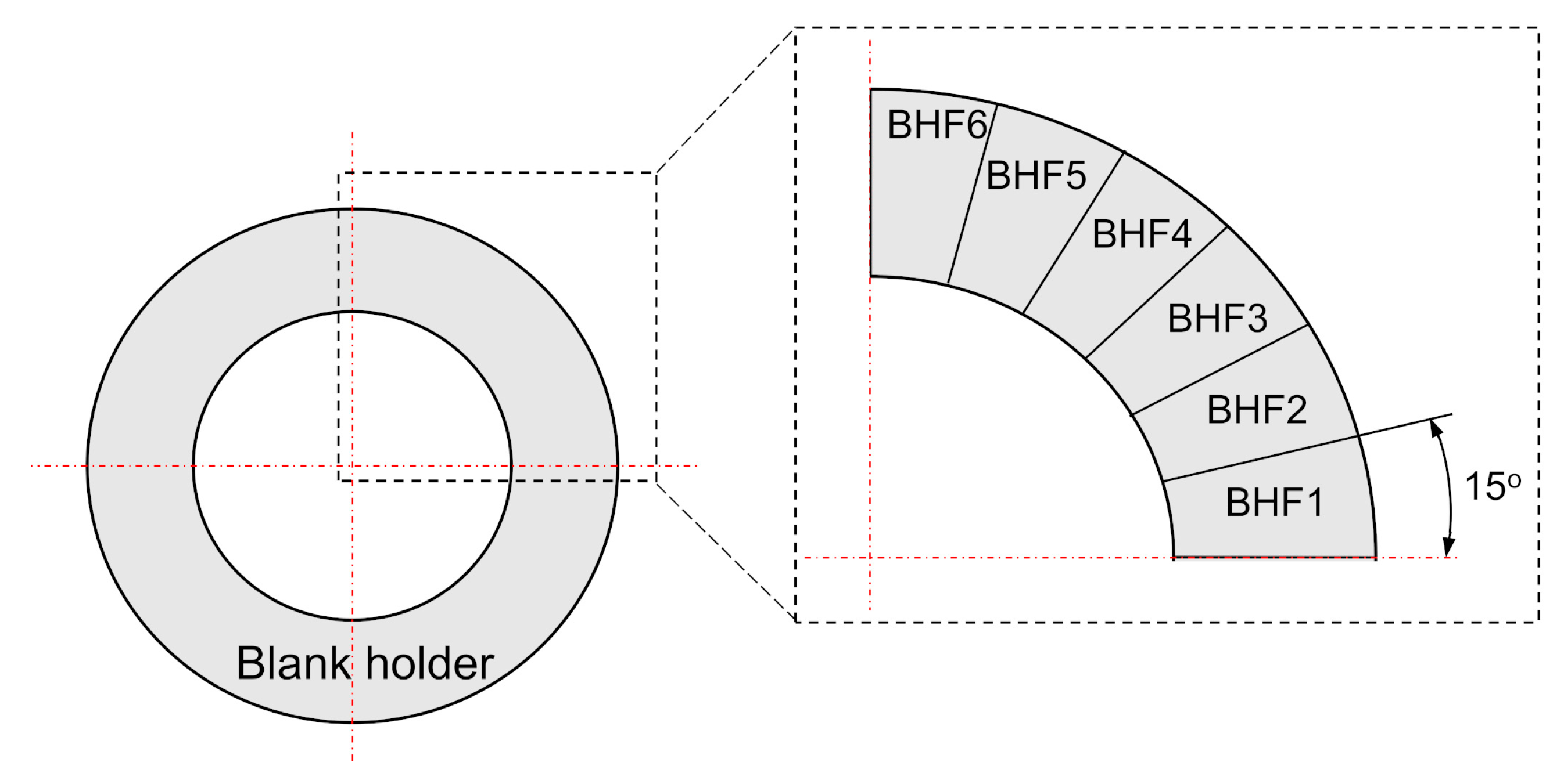
2.1. Design of Segmental Blank Holder

A schematic of the axis-symmetric deep drawing process is shown in Figure 1. Note that Rp and rp are the radius and corner radius of the punch, respectively. Rd and rd are the radius and corner radius of the die, respectively. Rb and t are the radius and thickness of the blank sheet, respectively.
In fact, the BHF provided by the conventional blank holder is primarily applied in a narrow region of the flange edge due to the increase in edge thickness during the deep drawing process [17]. In addition, because of the unsteady plastic-flow phase of the material, the BHF may not be effectively applied to the different flange regions of the sheet metal. This means that the sheet material in distinct flange regions would flow differently into the die cavity caused by the anisotropy of the sheet metal, resulting in the occurrence of earing. In order to overcome these drawbacks, a segmental blank holder was proposed to reasonably apply the varied BHF region by region on the flange of the sheet metal to make the material plastic-flow phase uniform in the die cavity, leading to the reduction of earing formation. For the sake of earing reduction, the greater the number of blank holder segments used, the more control over the earing reduction can be obtained [19]. In the present study, due to the orthogonal symmetry, only a quarter blank holder was generated to divide into six segments for introducing the varying BHF. The blank holder segments were determined and identified by the sensitivity analysis, in which the effect of the number of segments on the reduction of earing or improvement of formability was investigated. For the complex parts, the sensitivity analysis should be carried out to determine the appropriate number of segments. The schematic of the blank holder segment is shown in Figure 2, in which the varying BHF can be applied effectively on different flange regions. For this objective, the quarter blank holder consists of six segments with an accurate angle of 15°. Corresponding to each segment, the applied BHF is needed to properly determine the configuration that results in the greatest reduction of earing formation.

2.2. Analytical Model for Varying Blank Holding Force (BHF) with Segmental Blank Holder

Figure 3 shows the variation of the BHF corresponding to the variation of earing height. The principle of varying BHF is to reduce the BHF in regions where earing occurs and increase the BHF in the valley regions. For a better understanding, as shown in Figure 3, it can be observed that the earing was formed at 45° and 135° to the RD. Hence, the applied BHF in these regions should be relatively smaller than those at 0° and 90° to the RD. According to the study by Yoon et al. [36], the analytical formula for the prediction of earing can be successfully derived by considering both the r-value and yield stress directionalities simultaneously, as follows:
H c u p ( θ ) = t 0 + r c + R b ( 1 + r θ + 90 1 + 2 r θ + 90 ) [ ( R b R c ) r θ + 90 1 + r θ + 90 R c R b ] ( σ r e f σ ( θ ) Y ) β r θ + 90 1 + r θ + 90
where Hcup(θ) is the cup height and θ is the circumferential angle to the RD. The definition of other parameters in Equation (1) can be found in [36]. In this study, based on the variation of BHF as indicated in Figure 3, the analytical model for the determination of varying BHF applied on the blank holder segment, F(θ), is proposed as
F ( θ ) = α [ f ] + β [ f ] + γ
where α > 0, β < 0 and γ > 0 are the fitting parameters, while [f] is expressed as
[ f ] = { f , f > 0 0 , f 0
The [f] can be considered as a sign function of f, which is defined in the relationship with the earing height from Equation (1), expressed as
f = H c u p H a v g c u p [ H max c u p H min c u p ] / 2
Here, Hcup is the cup height as a function of θ + T/2, where T is the period that can be obtained from the earing height profile, as shown in Figure 3. The subscripts “avg”, “max”, and “min” correspond to the average, maximum, and minimum cup heights, respectively. By substituting Equation (4) into Equation (2), the magnitude of BHF for each segment can be determined analytically. According to Equation (4), f > 0 when the Hcup is larger than Hcupavg, and Equation (2) becomes F (θ) = α[f] + γ to illustrate the gradual increase of BHF applied above Hcupavg. Additionally, Equation (2) becomes F (θ) = β[−f] + γ in the case of f ≤ 0 when the Hcup is smaller than Hcupavg, indicating the gradual decrease of BHF provided below Hcupavg. Thus, a non-uniform BHF distribution is proposed so that the locally varying BHF is reduced and increased in the hill and valley regions, respectively, in order to induce uniform plastic-flow phase of the material.

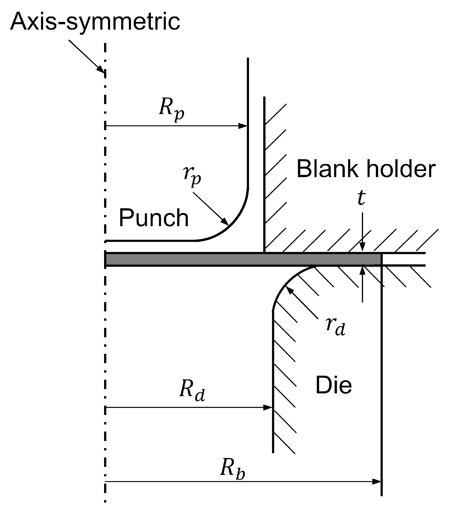
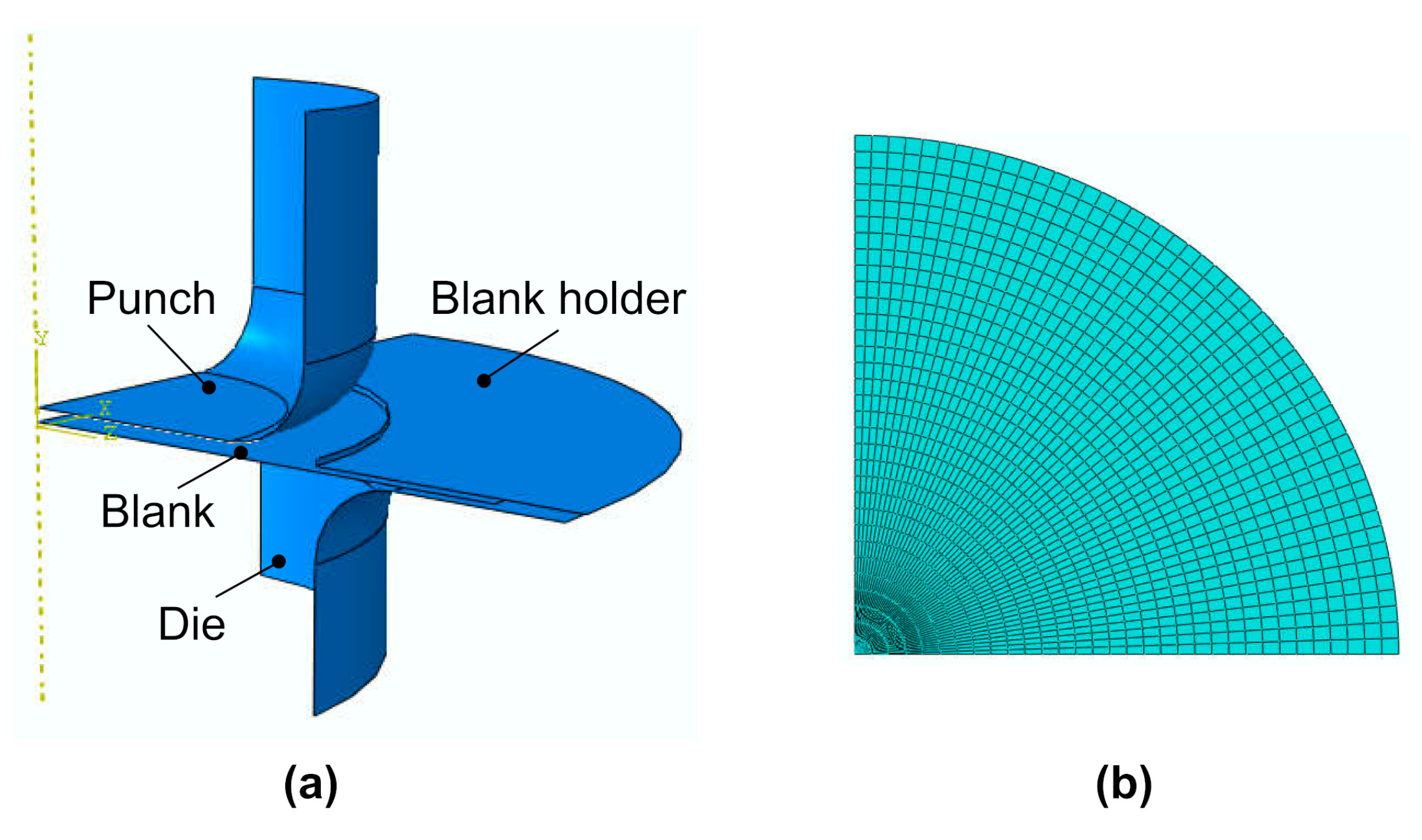
2.3. Finite Element Simulation of Deep Drawing

Using Hill’s 1948 anisotropic material model [37], available in the library of commercial software ABAQUS, a FE simulation of the deep drawing of an aluminum alloy sheet was carried out. Due to the orthogonal symmetry of the tool and blank geometries, only a quarter of the FE model is generated for the deep drawing simulation in order to save the computational time, as shown in Figure 4a. The blank sheet was initially meshed using a shell element (S4R) with the reduced integration. Figure 4b shows the FE mesh of the blank sheet with the total number of elements of 1600. The dimensions of the tool and the blank sheet for the FE simulation of deep drawing are given in Table 1 [36]. The punch, die, and blank holder are considered as rigid bodies whose material properties do not need to be defined. The die is fixed in all directions, while the punch can move in the vertical direction. The blank holder is used to apply force on the flange region of the blank sheet. A penalty contact is used between the tool and blank sheet by the surface-to-surface model. The Coulomb friction coefficient between the tool and the blank sheet is assumed to be 0.1 [38]. To investigate the effect of varying BHF on earing reduction in deep drawing, in the present study, the friction coefficient was assumed to be the same value in different flange regions of the sheet metal.
To investigate the effectiveness of varying BHF on earing reduction and thickness variation in deep drawing, an AA1050-O aluminum alloy sheet was used as the blank sheet material. The material properties of the AA1050-O blank sheet were chosen to be identical to those in Yoon et al. [39], as given in Table 2. Then, several FE simulations of deep drawing were carried out to determine the conditions under which a properly uniform BHF with less earing can be formed. An additional FE simulation was also performed using varying BHF to observe the reduction of earing formation in deep drawing.
In this work, the earing height variation, ΔH, was used to assess the earing reduction in the deep-drawn cup. Figure 5 shows a schematic of calculating ΔH, estimated as
Δ H = i = 1 n ( h i h a v g ) 2
where hi is the height of the ith node at the edge of the deep-drawn cup, while havg is the average height of these nodes, and n is the number of nodes at the edge of the deep-drawn cup.
Furthermore, for the sake of saving costs, FE simulations of deep drawing were carried out to generate the dataset for developing DNN model, which will be described in Section 3, and also study the effects of the material properties on the earing reduction in deep drawing by using the varying BHF. The same FE model was used while the material properties of the blank sheet varied. Accordingly, several material properties with different strength coefficients, K, and planar anisotropy, Δr, were chosen to perform the FE simulations of deep drawing by using the uniform and varying BHFs. For more comparisons, three different strength coefficients (132 MPa, 250 Mpa, and 500 MPa) and three different planar anisotropies (0.53, 0.77, and 1.04) were generated to investigate the effect of material properties on the earing reduction in deep drawing with varying BHF.
In order to achieve the optimal varying BHF by using the analytical model, a full factorial design is applied to determine the fitting parameter of α, β, and γ, as indicated in Equation (2). In this work, three levels of each factor were assumed as α: 1500, 2900, 4300; β: –650, –250, –450; and γ: 720, 820, 920. The levels of the three factors above were assumed so that 100 ≤ BHF ≤ 5000. The upper and lower limits were chosen to avoid the occurrence of wrinkling or tearing during the deep drawing process. Figure 6 shows the algorithm for the determination of the varying BHF based on the analytical model in conjunction with FE simulation. In the first step, the FE simulation was carried out by using a uniform BHF to obtain the earing formation in the deep-drawn cup. Then, the cup height was found to determine the parameter f using Equation (4). Accordingly, by substituting the [f] into Equation (2), the BHF for each segment was derived in terms of α, β, and γ. With given values of α, β, and γ, the full factorial design was used to generate matrix combinations for calculating the varying BHF. Next, the FE simulations were conducted with different varying BHFs. The criterion used to assess the effect of the varying BHF was the reduction of earing height variation. Finally, the optimal varying BHF, F(θ), was successfully determined in terms of the proper combination of α, β, and γ.

3. Integration of Deep Neural Network (DNN) with Genetic Algorithm (GA) for Optimization of Varying BHF

3.1. Deep Neural Network (DNN) Model

In fact, it is very difficult to establish the functional relationship between the earing height variation output and varying BHF input parameters by conventional mathematical methods. Figure 7 shows the DNN architecture, which is an efficiently predictive model for the prediction of earing height variation in this study. The three-layer DNN model including input, hidden, and output layers was performed by using a feedforward back-propagation neural network in the MATLAB environment. The transfer functions in the hidden and output layers were in the form of hyperbolic tangent sigmoid (tansig) and linear (purelin), respectively. The varying BHF of six segments and the earing height variation were defined as the input and output parameters, respectively. Thus, the number of neurons in the input and output layers were six and one, respectively. Figure 7 shows the DNN model consisting of three hidden layers with seven neurons for each layer. These were determined through the iteration method indicated in Figure 8. The performance of the DNN model was evaluated by mean square error (MSE) and coefficient of determination (R2) as follows:
M S E = 1 n i = 1 n ( y i y ^ i ) 2
R 2 = 1 i = 1 n ( y i y ^ i ) 2 i = 1 n ( y i y ¯ i ) 2
where y, y ^ , and y ¯ are the target, predicted, and average target values of earing height variation respectively, and n is the number of data samples used in the DNN model.
The full factorial design of varying BHF input parameters was used to generate the number of data samples for developing the DNN model. Three levels with low–middle–high values of each varying BHF (N) were chosen as 100, 2500, and 4900, respectively. Accordingly, the total of 729 models were simulated by the FE analysis for obtaining the earing height variation output. Prior to training, the input and output data were normalized in the range of 0 and 1 to increase accuracy and speed of the network. Then, the DNN was trained and validated by 442 and 189 data samples of input and output, respectively. The remaining data samples were not used in the DNN model because the earing height variation output could not be obtained from the simulation due to the occurrence of tearing during the deep drawing process.

3.2. DNN-Genetic Algorithm (GA) Optimization Model

GA has been widely used to solve the optimization problems based on the mechanics of natural genetics and natural selection. In the present study, the developed DNN model in conjunction with GA was proposed and carried out for the prediction and optimization of varying BHF parameters in the objective of minimum earing height variation. The uniqueness of the integrated DNN-GA model is capable of finding the optimized variables without giving the explicitly mathematical function of the objective, since the trained DNN model is used as an objective function in GA to calculate the fitness value. The procedure for implementing the DNN-GA optimization algorithm is presented in Figure 8. First, the algorithm is started with the development of the DNN model. By changing the number of hidden neurons and layers, a number of network architectures are investigated. The architecture that shows the highest performance in terms of MSE and R2 for prediction is considered as the best DNN model. Next, the GA is performed by randomly generating the initial population. Based on the best trained DNN model, the fitness is calculated for all initial individuals. As the criteria optimization is not satisfied, the new generation is reproduced by using three operators of selection, crossover, and mutation. The process is repeated until the maximum population size or generation size is reached. In this work, the population and generation sizes were given as 100 and 200, respectively. The probability of crossover rate and mutation were set as 0.85 and 0.01, respectively, to establish the DNN-GA model and then optimize the varying BHFs for minimum earing height variation.

4. Results

4.1. Verification of the Present Finite Element Analysis (FEA)

In order to verify the accuracy of the present finite element analysis (FEA), the analytical and experimental results presented by Yoon et al. [36] for aluminum AA2090-T3 sheet material were used. The FE model was generated with the same geometry and material properties as given in Table 1 and Table 2. Additionally, the same blank holding force of 22.2 kN was used in this verification. As shown in Figure 9, the prediction of the earing height profile using the present FEA is represented in comparison with the previous report [36]. Figure 9 shows that the number of predicted ears correlated well with the analytical and experimental findings [36]. The result based on the present FEA showed that the cup height at 0° was higher than the height at 90°, which was in good agreement with the previous experiment. This demonstrates that the present FEA predicted the earing trend correctly and showed good consistency with the earlier works [36]. In addition, the predicted earing could also be confirmed by the theoretical analysis using planar anisotropy, Δr, which is defined as
Δ r = r 0 2 r 45 + r 90 2
where r0, r45, and r90 are the anisotropy coefficients of the sheet metal at 0°, 45°, and 90° to the RD, respectively. According to the theoretical analysis, ears are formed at 45° to the RD as the negative planar anisotropy; in contrast, ears are observed at 0° and 90° to the RD if the planar anisotropy is positive [40]. Here, the anisotropy coefficients of AA2090-T3 are given in Table 2 [38]. As the planar anisotropy was negative (Δr = −1.125), ears were found at 45° to the RD, as indicated in Figure 9. Therefore, the present FEA revealed that the prediction of earing was in good agreement with the previous analytical and experimental results [36] as well as the theoretical analysis. This means that the present FEA was successfully verified and could be used in this study.

4.2. Prediction of Earing by Using the Uniform BHF

First, the FE simulations of deep drawing were conducted using BHFs of 0.05 kN and 15 kN, respectively. It was observed that wrinkling occurred when the BHF was not enough to prevent the buckling of the blank sheet, and tearing appeared due to the insufficient material flow when the BHF was excessive [19]. Next, the predictions of earing in deep drawing using various uniform BHFs of 1 kN, 3 kN, and 5 kN were carried out, as shown in Figure 10. The present FEA predicted that the height of the deep-drawn cup monotonically decreases from 0° to 45° to the RD and monotonically increases from 45° to 90° to the RD. This is due to the contribution of the yield stress directionality [36]. As the planar anisotropy was positive (Δr = 0.530), the formation of earing was observed at 0° and 90° to the RD, which well correlated with the theoretical analysis [40]. It can be seen that four main ears formed at 0°, 90°, 180°, and 270° in the cup deep drawing process. This is partially attributed to the slower flow of sheet metal into the die cavity in these regions than in the other ones. The results show that the uniform BHFs of 1 kN and 3 kN exhibited two bigger ears at 0° and 180° as well as two smaller ears at 90° and 270°. Meanwhile, the uniform BHF of 5 kN predicted almost the same four ears at 0°, 90°, 180°, and 270°. The results revealed that the height of earing, the peaks of the waves shown in Figure 10, increased when the BHF increased [15]. A significant increase of earing height was observed at 90° and 270° with the larger BHF. By using Equation (5), the earing height variation, ΔH, can then be determined. The numerical values of ΔH for uniform BHFs of 1 kN, 3 kN, and 5 kN were 12.38 mm, 12.94 mm, and 13.76 mm, respectively. This result illustrates that the ΔH also increased with the increase in BHF.
Since the r-values were used in Hill’s 1948 yield function for FE simulation of deep drawing, the strain state of the deep-drawn cup was observed. Figure 11 shows the contour plots of the equivalent plastic strain of the deep-drawn cup using the uniform BHFs of 1 kN, 3 kN, and 5 kN. Note that the labels of SNEG and SPOS in the legend represent the interior and exterior surfaces of the deep-drawn cup, respectively. Due to the quadratic Hill yield function, the equivalent plastic strain distributions are predominantly concentrated in four regions, leading to four major ears [37]. As shown in Figure 11, the maximum (Max) equivalent plastic strains were obtained to be 0.78, 0.81, and 1.03 by using the uniform BHFs of 1 kN, 3 kN, and 5 kN, respectively. The result revealed that the equivalent plastic strain increased when the BHF increased. Moreover, comparing the various uniform BHFs of deep drawing illustrated that the equivalent plastic strain in the case of BHF using 5 kN was more critical than that of using the uniform BHFs of 1 kN and 3 kN. This high level of plastic strain can induce tearing defects in deep drawing when a larger BHF is introduced [14]. With these drawbacks, it can be seen that there is a limit to reducing earing formation in deep drawing with uniform BHF. Therefore, varying the BHF by using the segmental blank holder is proposed to reduce earing in deep drawing.

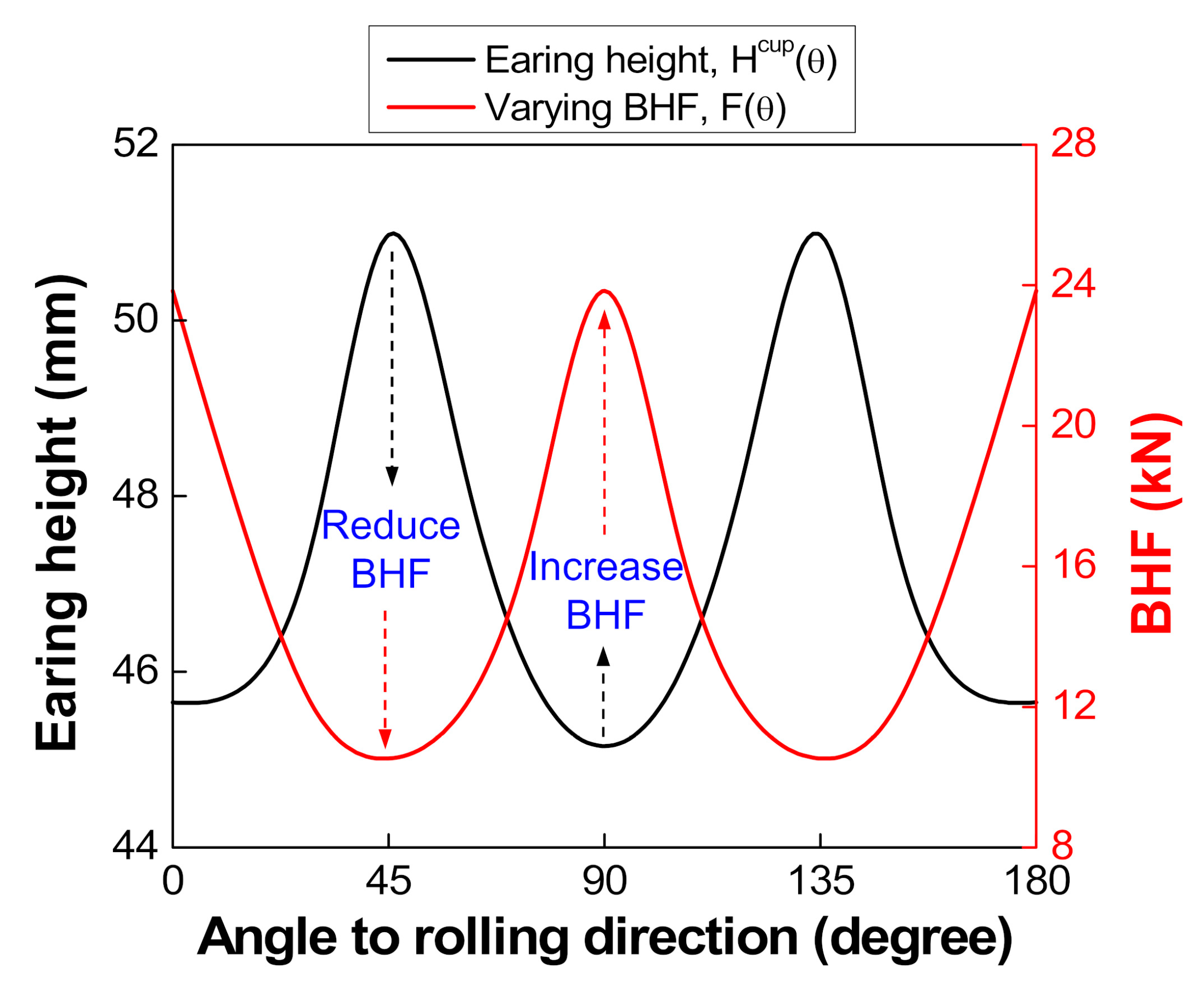
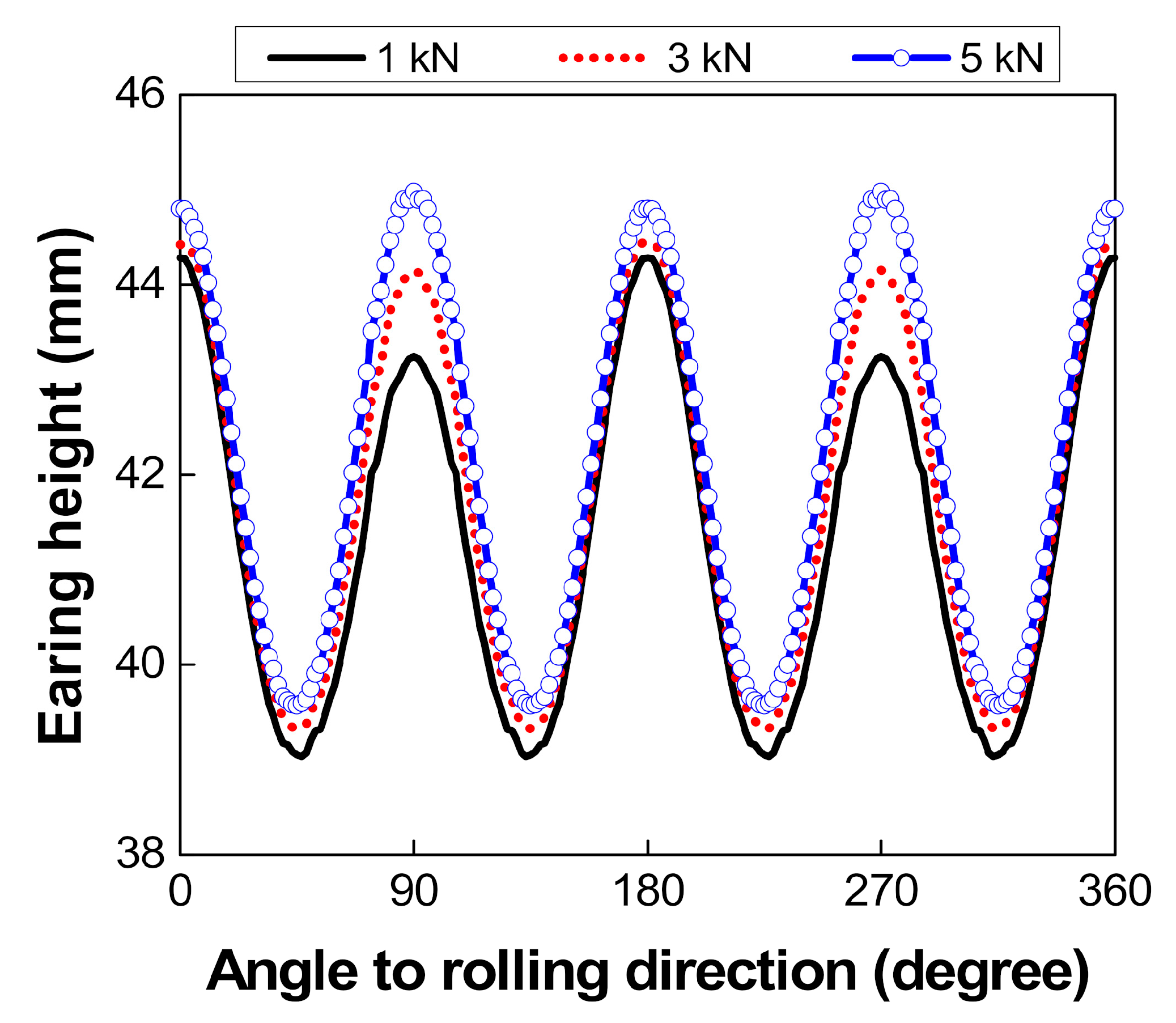
4.3. Effect of Varying BHF on Earing Reduction

Figure 12 shows the variation of BHF and its effect on the earing height profiles with three cases of varying BHF obtained by using the analytical model. According to Equation (2), three combinations of α, β, and γ were selected from the full factorial design to calculate three cases of varying BHF, as indicated in Figure 12a. It was observed that the BHF continuously varied region by region in the flange of the sheet metal with a greater amount of BHF at the valley region corresponding to the earing profile to control the plastic-flow phase of material into the die cavity. This confirms that the proposed analytical model was properly established to determine the varying BHF for investigation of earing reduction in deep drawing. Figure 12b shows a comparison of earing height profiles by using the uniform and three-case varying BHFs. For the sake of comparison, the predicted earing using the uniform BHF of 3 kN was used as a reference. It was also noted that all the FEA conditions including material properties, type and size of mesh, and friction coefficient were the same in the case of using uniform BHF, except for applying different varying BHFs by using a segmental blank holder. The result reveals that the varying BHF had a significant effect on the cup height as well as the reduction of earing. As shown in Figure 12b, the cup height increased by using the varying BHF, while the earing height variation noticeably decreased. In comparison with the uniform BHF, it was observed that the cup height considerably increased at 0° and 45° to the RD while little change of the cup height was observed at 90° to the RD with the varying BHF, leading to the decreased earing height variation. The result shows that with the different varying BHFs, the reduction of earing also varied. The numerical values of earing height variation, ΔH, were calculated to be 10.21 mm, 9.57 mm, and 8.82 mm by using the different varying BHFs with case 1, case 2, and case 3, respectively. These values were less than that of 12.94 mm in the case of using the uniform BHF. This result demonstrates that the earing in deep drawing can be reduced with varying BHF. In order to obtain the greatest reduction in earing, the optimal varying BHF was determined based on the analytical model in combination with the FE simulation. According to the procedure as indicated in Figure 6, the optimal combination of α, β, and γ can be found as α = 4300, β = −650, and γ = 720. By substituting these values into Equation (2), the final equation for the calculation of optimal varying BHF is obtained as
F = 4300 [ f ] 650 [ f ] + 720

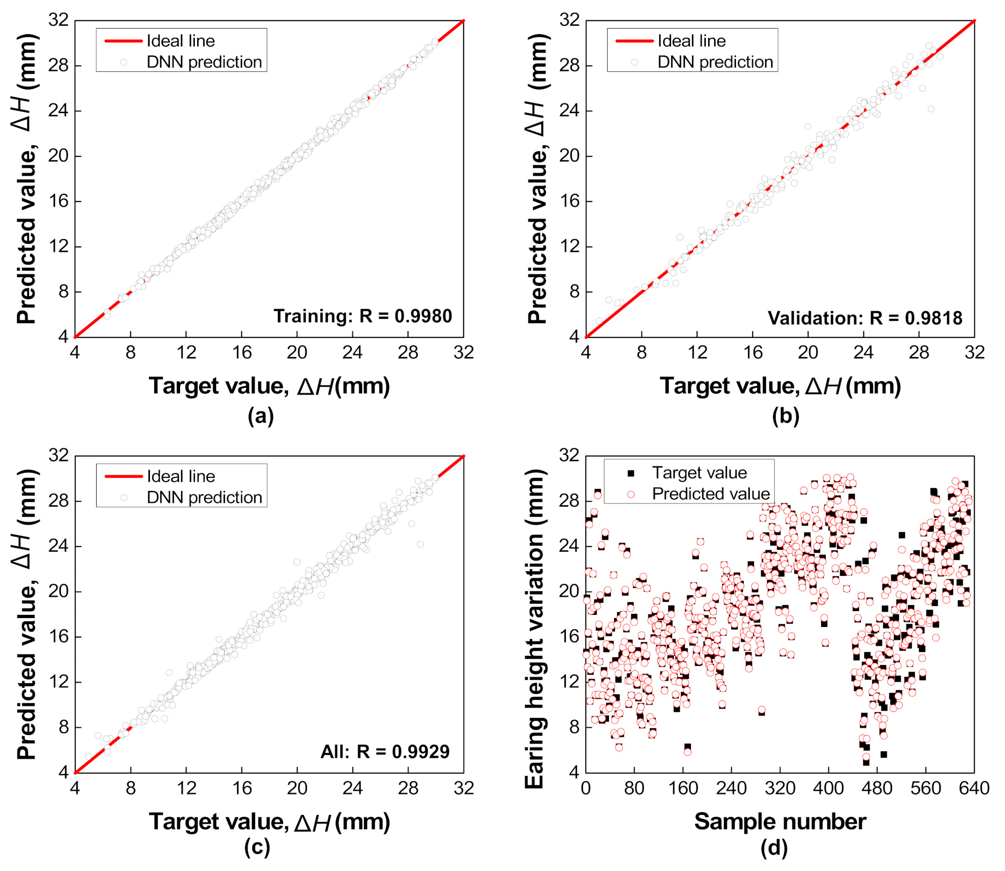
4.4. Prediction of Earing Height Variation by the DNN Model

Figure 13 shows the DNN model prediction for earing height variation with the coefficient of determinations and compared the results between the target and predicted values. The results show that the DNN model with three hidden layers of seven neurons in each layer accurately reproduced the earing height variation with the best value of overall R2 = 0.99. The comparison revealed that the DNN prediction was in good agreement with the FE results. This indicates that the developed DNN model was reasonable and able to be used as the fitness function in GA for optimization of the varying BHF parameters.

4.5. Optimization of Varying BHF with Integrated DNN-GA Model

The optimized varying BHF for minimization of earing height variation was successfully obtained by using the integrated DNN-GA model, as given in Table 3.
The results before and after optimizations were well compared. Note that the varying BHF indicated by before optimization was selected as the best result among all of the full factorial designs. Figure 14 shows the earing height profile by using uniform BHF in a comparison of varying BHFs between before and after optimizations. It can be seen that there was a negligible difference between the results before and after optimization. This means that the integrated DNN-GA can accurately predict the optimization of varying BHF. In order to obtain the result before optimization, it is time-consuming and has a high manufacturing cost for implementing a great number of experiments by using full factorial design. Thus, the integrated DNN-GA model is a robust and efficient alternative for overcoming these disadvantages. In addition, compared to the uniform BHF, the results after optimization by the DNN-GA model were noticeably decreased in earing height variation. The significant increase of cup height at 45° and nearly retained cup height at 90° to the RD resulted in the reduction of the earing height variation. In comparison with the ΔH of 12.94 mm from the uniform BHF, the use of the varying BHF predicted by the DNN-GA model showed a considerable decrease of ΔH by ~52% to 6.24 mm, as shown in Table 3. Furthermore, Figure 14b compares the relative earing height between the uniform and varying BHFs. The relative earing height is determined as
Relative   earing   height   ( % )   = H cup H min cup H min cup × 100
where Hcup and Hcupmin are the cup height and minimum cup height of the deep-drawn cup, respectively. In the comparison between before and after optimization, the results also showed the insignificant difference in the percentage of earing height above the minimum cup height. However, in the case of using the uniform BHF, it revealed the result of 12–13%, which decreased significantly to 4–7% with the optimized varying BHF by the integrated DNN-GA model. The result reveals the remarkable reduction of earing height variation by using the varying BHF. This means that the DNN-GA model performed in this study is capable of the prediction and optimization of input parameters with minimization of the objective.

5. Discussion

5.1. Comparison of Analytical and DNN-GA Models

In the present study, a comparison of analytical and DNN-GA models used to obtain the optimal varying BHF was well discussed. With the analytical model, the optimal varying BHF was calculated by using Equation (9) and was also determined from the DNN model using GA. The magnitudes of two optimal varying BHFs are given in Table 3 for the purpose of comparison. This indicates that the two approaches can provide a similar result of varying BHF. The earing height variation obtained by two optimal results also exhibited a negligible difference. Figure 15 shows the results of earing height and relative earing height profiles of the deep-drawn cup by using the optimal varying BHFs in a comparison between the analytical and DNN-GA models. It can be obviously seen that the optimal varying BHFs obtained by the analytical and DNN-GA models resulted in the same trend of earing height profiles with a slight discrepancy. This implies that the developed DNN-GA model in this study is comparable and efficient to achieve the optimization of varying BHF, which leads to the reduction of earing in deep drawing. Figure 15a shows that both optimal varying BHFs had a substantial influence on the earing formation. In fact, compared to the uniform BHF, the optimal varying BHFs revealed a considerable decrease in earing height variation by ~45% and ~52% with the analytical and DNN-GA models, respectively, as indicated in Table 3.
In addition, Figure 15b shows the relative earing height in comparison between the analytical and DNN-GA models. It can be observed that the percentage of earing height above the minimum cup height by using two optimal results was not much different apparently. However, it revealed a remarkable decrease compared to the uniform BHF. The result implies that the varying BHF, which can be optimized by both the analytical and integrated DNN-GA models, using the segmental blank holder is more reasonable for the reduction of earing formation than the uniform BHF using the conventional blank holder in the deep drawing process.

5.2. Thickness Variation in Different Directions

The current results have clearly shown the significant effect of the varying BHF on earing reduction in deep drawing. The ability and reliability of the proposed method in the thickness variations of deep-drawn cups are discussed. Figure 16 shows the sheet thickness distribution of deep-drawn cups by the use of uniform BHF in comparison to the optimal varying BHFs obtained by the analytical and DNN-GA models. The results reveals a slight decrease in thickness by using both optimal varying BHFs compared to the uniform BHF. It can be observed that the maximum thinning was found in the corner region of the deep-drawn cup. As shown in Figure 16, the numerical values of maximum thinning using the optimal varying BHFs obtained by the analytical and DNN-GA models were 1.41 and 1.44, respectively, which were only a little lower than that of 1.48 with the result of using uniform BHF. The result showed an increase of thinning in the deep-drawn cup by using the optimal varying BHF, but was very negligible.
In this study, the maximum thinning rate, θmax was used to assess the occurrence of tearing in deep drawing, expressed as [41]
θ max = 1 t min t i n i t i a l
where tinitial is the initial thickness of the blank sheet (tinitial = 1.6 mm), and tmin is the minimum thickness of the deep-drawn cup (tmin = 1.48 mm, 1.41 mm, and 1.44 mm for using the uniform and two optimal varying BHFs, respectively). By substituting these values into Equation (11), the maximum thinning rates were obtained as 0.08, 0.12, and 0.10, respectively. Generally, the maximum thinning rate cannot exceed the critical thinning rate of the sheet material, which was taken as 0.25, according to prior experience [12]. The result revealed that the maximum thinning rates by using the uniform and optimal varying BHFs were much lower than the critical thinning rate. This implies that there would be no occurrence of tearing in the deep-drawn cup by using the varying BHF.
In order to further observe the thickness variation, the thickness of the deep-drawn cup was estimated along the RD, DD, and TD at three different regions of the cup: (I) cup bottom, (II) cup corner, and (III) cup wall, as shown in Figure 17. Note that the reference point is taken from the center of the cup bottom. Figure 18 shows the thickness variations of the deep-drawn cup along the RD, DD, and TD using the uniform and two optimal varying BHFs. The results show a non-uniform thickness distribution at different regions of the deep-drawn cup due to the different strain states [42]. At the top of the cup wall region, the thickness distribution in the RD, DD, and TD by using the uniform and optimal varying BHFs was higher than the initial thickness (tinitial = 1.6 mm). This is due to the radial tensile and circumferential compressive stress states in the flange region. According to the previous reports [42,43], the compressive stress along the circumferential direction can contribute to the increase in the thickness of the blank sheet. A decreased thickness was observed at the cup bottom due to the experiences of the biaxial tensile stress state and the friction between the punch and the blank sheet. Meanwhile, the maximum thinning of the deep-drawn cup was found at the cup corner region due to the plane strain condition; however, it was very negligible. In the comparison between the results of using the analytical and DNN-GA models, the thickness in different directions revealed a similar variation. Additionally, it showed a slight decrease in thickness compared to the uniform BHF due to the increase in the deep-drawn cup height [44]. The interesting point is the increase in thickness in the case of using the optimal varying BHF observed at the cup wall region in the TD. This is due to the decrease in varying BHF toward the end of the deep drawing process, leading to the lower tensile stress in the wall region of the blank sheet. Overall, the difference in thickness of the deep-drawn cup between the uniform and varying BHFs was insignificant. It can be concluded that the varying BHF is an effective method to minimize earing formation in deep drawing with little influence on the thickness variation in the deep-drawn cup. Although the blank holding force of a segmental holder was held constant in the present study, the time dependence of the BHF seems to be important for further study.

5.3. Effect of the Material Properties on Earing Reduction

Even though the varying BHF has been utilized, there is also a limit on the further reduction of the earing since the formation of earing predominantly depends on the material properties. In fact, the material properties, especially the plastic anisotropy, significantly affect the quality of the deep-drawn cup, which results in the formation of earing. For example, the prediction of more than four ears was observed by involving more anisotropy coefficients of yield function in the FE model [45]. It has been also reported that the anisotropy parameters are correlated with the enlarging, number, and direction of ears, while the planar anisotropy is associated with the enlarging and size of ears [40]. Moreover, the contribution of r-value and yield stress directionalities plays an important role in predicting the earing of the deep-drawn cup [36].
Furthermore, FE simulations of deep drawing were also carried out to study the effect of the material properties on the earing reduction in deep drawing by using the varying BHF. Figure 19 shows the prediction of earing height profiles by using the uniform and varying BHFs for AA2090-T3, which is a highly anisotropic material. The results showed that significant earing was predicted due to the high anisotropy. Since the planar anisotropy was negative (Δr = −1.125), the earing formation was observed at 45° to the RD, which is in good agreement with the theoretical analysis [40]. By using the uniform BHF, it can be seen that the AA2090-T3 sheet material showed a higher discrepancy between the maximum and minimum cup height than that of the AA1050-O sheet material, which is a low-anisotropy material. It has been also observed that the highly anisotropic material of AA2090-T3 exhibited a higher cup height variation than that of the mildly anisotropic material of AA6022-T4 [46]. By introducing the varying BHF, which is determined by using the analytical model, the earing height profile was predicted. As shown in Figure 19a, the result of using the varying BHF revealed an insignificant influence on the reduction of earing formation for the highly anisotropic material of AA2090-T3. By varying the BHF, it was observed that the cup height had an increase at 0° to the RD; however, very little change on the cup height was observed at 45° and 90° to the RD. This may lead to a negligible effect on the reduction of earing height variation by using the varying BHF. Indeed, the earing height variations, ΔH, were determined to be 26.45 mm and 24.04 mm for the uniform and varying BHFs, respectively. This result reveals that the reduction of earing height variation was less than 10%. This can be better observed by the result of relative earing height, as shown in Figure 19b. By using the uniform BHF, the percentage of earing height above the minimum cup height was obtained as ~27%, while a negligible decrease to ~26% was observed by using the varying BHF. The result showed that the reduction of earing in deep drawing by varying the BHF for the highly anisotropic material of AA2090-T3 was inconsiderable.
Moreover, several different material properties with strength coefficient, K, and planar anisotropy, Δr, were chosen to further investigate the effect of the material properties on the earing reduction in deep drawing by using the varying BHF. Table 4 shows the reduction of earing height variation corresponding to the K and Δr. The reduction of earing height variation is estimated as
r e d u c t i o n = Δ H Δ H × 100
where ΔH′ and ΔH are the earing height variations calculated using the varying and uniform BHFs, respectively. It can be observed that a material with a greater combination of K and Δr showed less influence on the reduction of earing height variation. As shown in Figure 20, the reduction of earing height variation monotonically increased with the decrease of the K and Δr simultaneously. This result demonstrates that the lower the material strength, the greater the effect on the reduction of earing formation in deep drawing by using the varying BHF that can be obtained.

6. Conclusions

In the present study, the varying blank holding force (BHF) by using the segmental blank holder was proposed to investigate its effect on the earing reduction in the circular deep drawing process of aluminum alloy sheet. The following conclusions of this study can be summarized as follows:
(i)
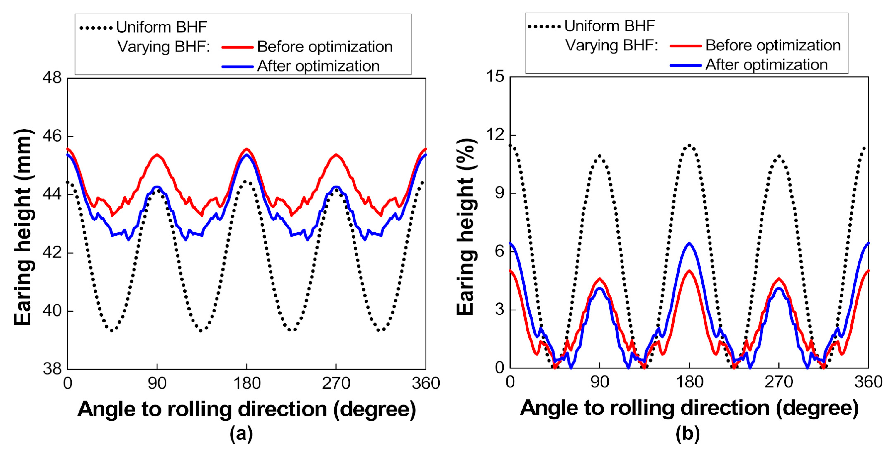
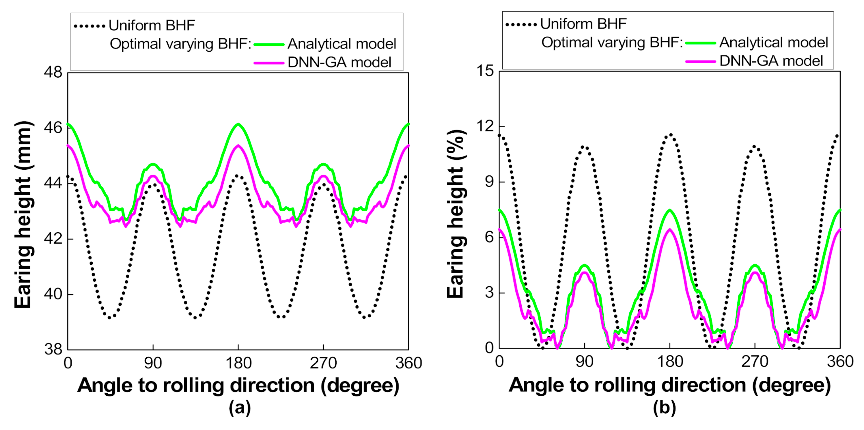
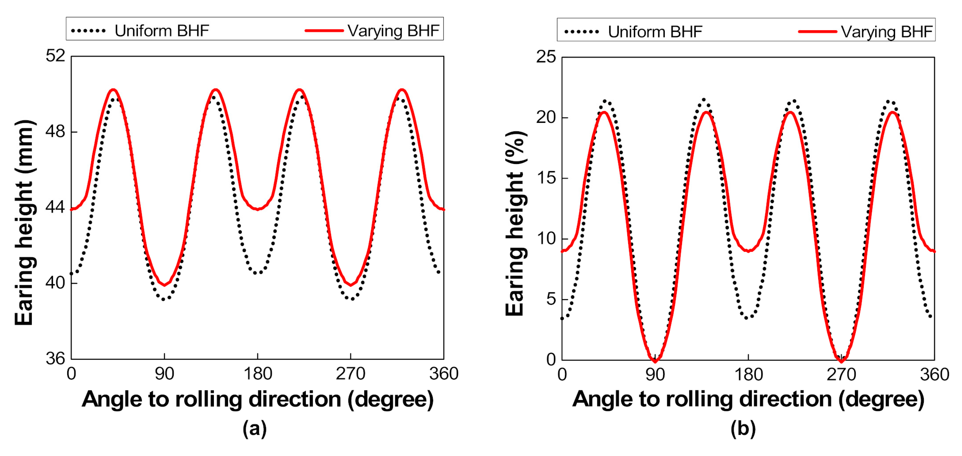
With an interval holder-segment angle of 15°, the different varying BHFs obtained by the analytical model resulted in the different influences on earing reduction. The noticeable decrease of earing height variation by ~45% was revealed by the optimal varying BHF, indicating a more reasonable technique with varying BHF than the uniform BHF for earing reduction in deep drawing.
(ii)
The developed deep neural network (DNN) model with the integration of genetic algorithm (GA) revealed the optimization of varying BHF with a considerable reduction in earing height by ~52%, which showed a superior result to the analytical model. This confirmed that the proposed DNN-GA model effectively predicted and optimized the process parameters in this study.
(iii)
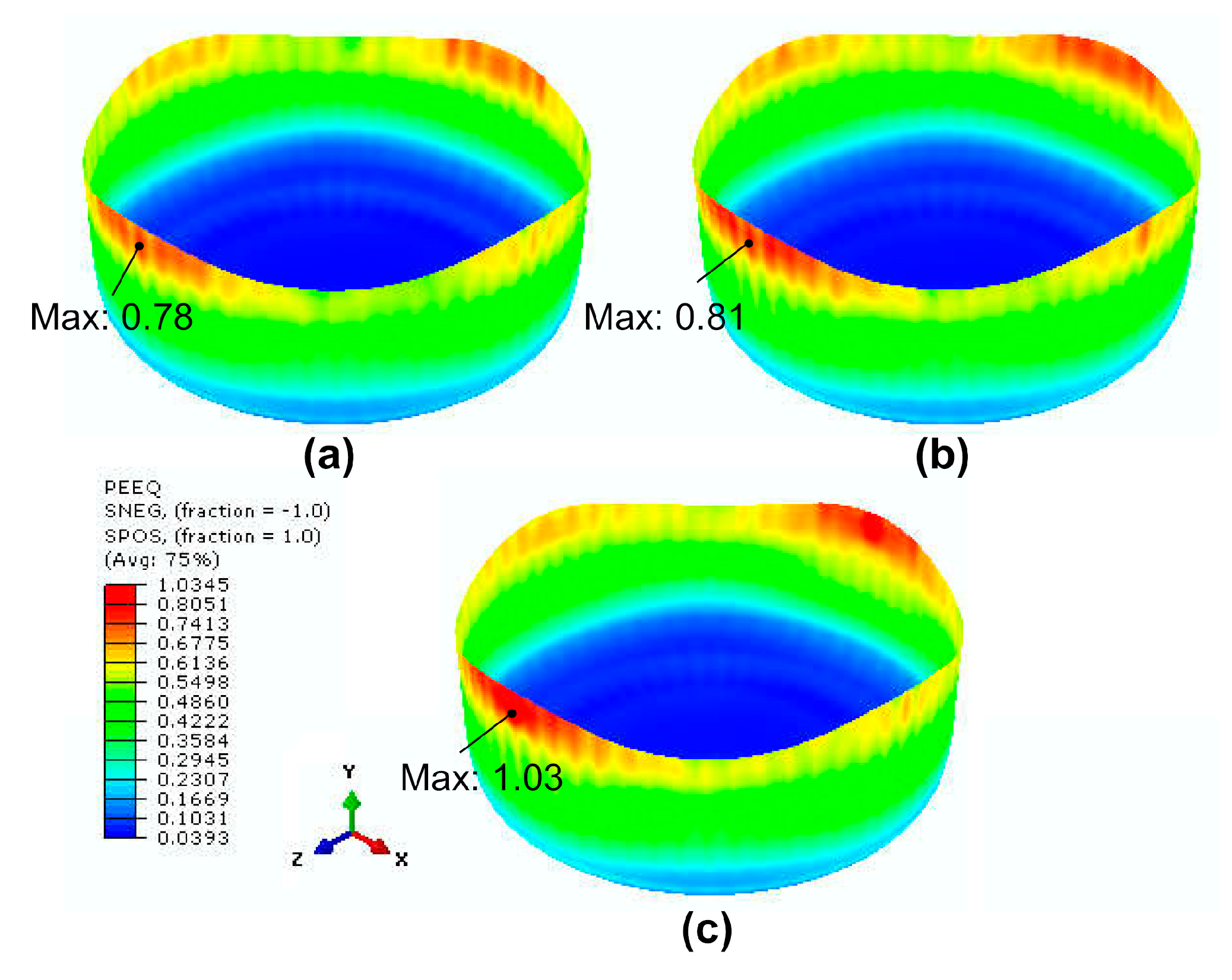
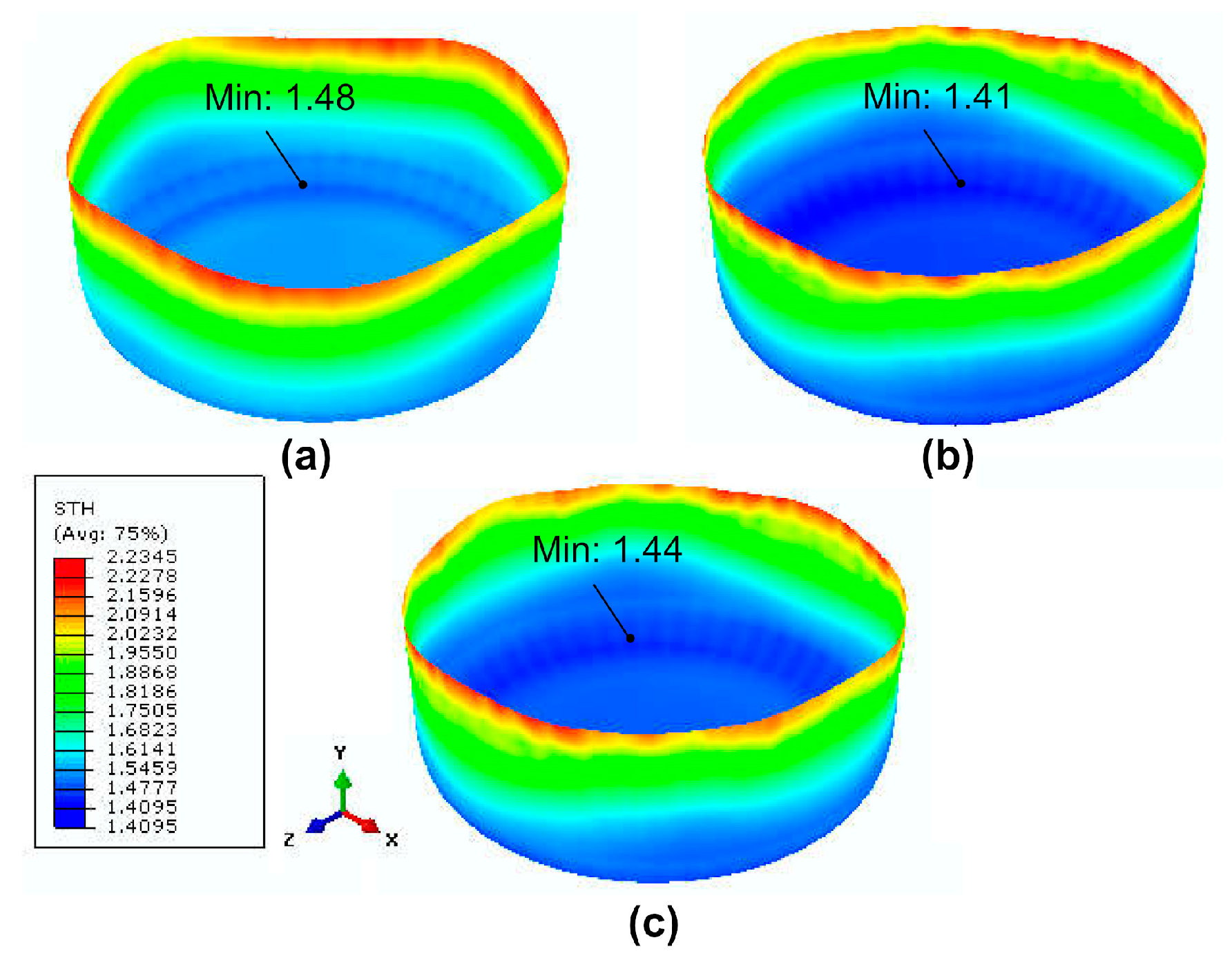
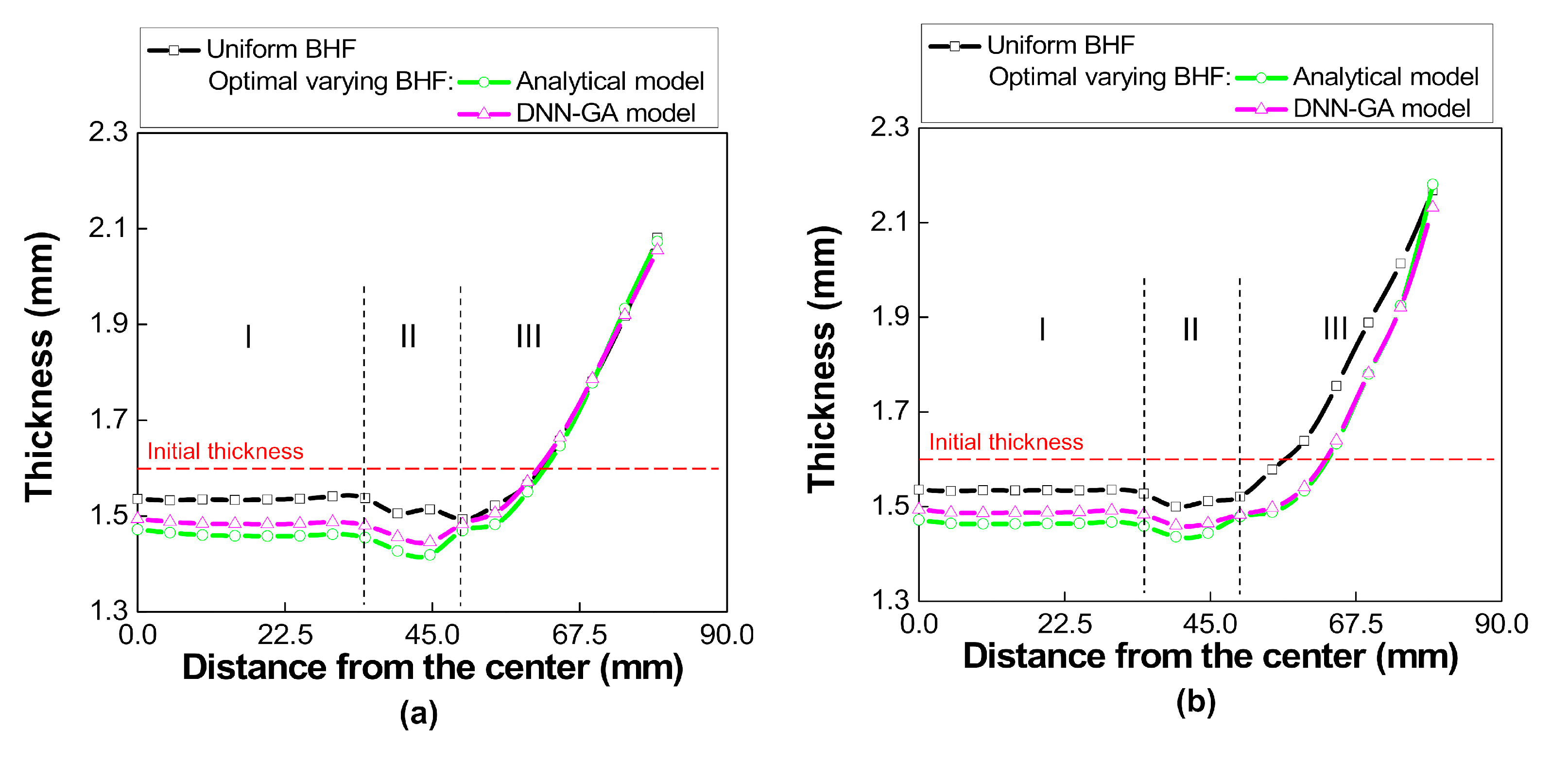
For a volume consistency, the non-uniform thickness distribution was observed with an increase of thickness in the transverse direction at the cup wall region by varying BHF, which indicated an improvement in deep-drawability. Although BHF of a segmental holder was held constant in the present study, the time dependence of the BHF seems to be important for further study.
(iv)
Furthermore, the present study revealed that, due to the effect of material properties on earing formation, the lower the material strength, the greater the effect on the earing reduction in deep drawing with the varying BHF will be.

Author Contributions

Conceptualization, M.T.T. and D.-K.K.; Validation, M.T.T., H.W.L., and D.-K.K.; Investigation, M.T.T. and Z.S.; Writing—original draft preparation, M.T.T.; Writing—review and editing, D.-K.K.; Visualization, M.T.T. and Z.S.; Supervision, H.W.L. and D.-K.K.; Funding acquisition, D.-K.K. All authors have read and agreed to the published version of the manuscript.

Funding

This research received no external funding.

Acknowledgments

This work was supported by the Research Fund of the University of Ulsan.

Conflicts of Interest

The authors declare no conflict of interest.

References

  1. Benke, M.; Schweitzer, B.; Hlavacs, A.; Mertinger, V. Prediction of Earing of Cross-Rolled Al Sheets from {h00} Pole Figures. Metals 2020, 10, 192. [Google Scholar] [CrossRef] [Green Version]
  2. Engler, O.; Knarbakk, K. Temper rolling to control texture and earing in aluminium alloy AA 5050A. J. Mater. Process. Technol. 2021, 288, 116910. [Google Scholar] [CrossRef]
  3. Guo, N.; Wang, J.; Sun, C.; Zhang, Y.; Fu, M. Analysis of size dependent earing evolution in micro deep drawing of TWIP steel by using crystal plasticity modeling. Int. J. Mech. Sci. 2020, 165, 105200. [Google Scholar] [CrossRef]
  4. Hlavacs, A.; Szucs, M.; Mertinger, V.; Benke, M. Prediction of Earing of Hot-Rolled Al Sheets from Pole Figures. Metals 2021, 11, 99. [Google Scholar] [CrossRef]
  5. Kishor, N.; Kumar, D.R. Optimization of initial blank shape to minimize earing in deep drawing using finite element method. J. Mater. Process. Technol. 2002, 130, 20–30. [Google Scholar] [CrossRef]
  6. Singh, A.; Basak, S.; PS, L.P.; Roy, G.G.; Jha, M.N.; Mascarenhas, M.; Panda, S.K. Prediction of earing defect and deep drawing behavior of commercially pure titanium sheets using CPB06 anisotropy yield theory. J. Manuf. Process. 2018, 33, 256–267. [Google Scholar] [CrossRef]
  7. Aretz, H.; Engler, O. Accuracy analysis of earing compensation procedures. Int. J. Solids Struct. 2020, 191–192, 418–433. [Google Scholar] [CrossRef]
  8. Jankree, R.; Thipprakmas, S. Achievements of Nearly Zero Earing Defects on SPCC Cylindrical Drawn Cup Using Multi Draw Radius Die. Metals 2020, 10, 1204. [Google Scholar] [CrossRef]
  9. Zhao, Z.; Mao, W.; Roters, F.; Raabe, D. A texture optimization study for minimum earing in aluminium by use of a texture component crystal plasticity finite element method. Acta Mater. 2004, 52, 1003–1012. [Google Scholar] [CrossRef]
  10. Engler, O.; Aegerter, J.; Calmer, D. Control of texture and earing in aluminium alloy AA 8011A-H14 closure stock. Mater. Sci. Eng. A 2020, 775, 775. [Google Scholar] [CrossRef]
  11. Vahdat, V.; Santhanam, S.; Chun, Y.W. A numerical investigation on the use of drawbeads to minimize ear formation in deep drawing. J. Mater. Process. Technol. 2006, 176, 70–76. [Google Scholar] [CrossRef]
  12. Feng, Y.; Hong, Z.; Gao, Y.; Lu, R.; Wang, Y.; Tan, J. Optimization of variable blank holder force in deep drawing based on support vector regression model and trust region. Int. J. Adv. Manuf. Technol. 2019, 105, 4265–4278. [Google Scholar] [CrossRef]
  13. Kitayama, S.; Koyama, H.; Kawamoto, K.; Miyasaka, T.; Yamamichi, K.; Noda, T. Optimization of blank shape and segmented variable blank holder force trajectories in deep drawing using sequential approximate optimization. Int. J. Adv. Manuf. Technol. 2016, 91, 1809–1821. [Google Scholar] [CrossRef]
  14. Zhong-Qin, L.; Wu-Rong, W.; Guan-Long, C. A new strategy to optimize variable blank holder force towards improving the forming limits of aluminum sheet metal forming. J. Mater. Process. Technol. 2007, 183, 339–346. [Google Scholar] [CrossRef]
  15. Demirci, H.I.; Esner, C.; Yasar, M. Effect of the blank holder force on drawing of aluminum alloy square cup: Theoretical and experimental investigation. J. Mater. Process. Technol. 2008, 206, 152–160. [Google Scholar] [CrossRef]
  16. Van, T.P.; Jöchen, K.; Böhlke, T. Simulation of sheet metal forming incorporating EBSD data. J. Mater. Process. Technol. 2012, 212, 2659–2668. [Google Scholar] [CrossRef]
  17. Zhang, H.; Qin, S.; Cao, L.; Meng, L.; Zhang, Q.; Li, C. Research on Deep Drawing Process Using Radial Segmental Blank Holder based on Electro-permanent Magnet Technology. J. Manuf. Process. 2020, 59, 636–648. [Google Scholar] [CrossRef]
  18. Hassan, M.; Takakura, N.; Yamaguchi, K. Friction aided deep drawing using newly developed blank-holder divided into eight segments. Int. J. Mach. Tools Manuf. 2003, 43, 637–646. [Google Scholar] [CrossRef]
  19. Han, J.; Yamazaki, K.; Makino, S.; Shirasawa, T. Optimization of Deep Drawing Process for Circular Cup Forming. In Proceedings of the 10th World Congress on Structural and Multidisciplinary Optimization, Orlando, FL, USA, 19–24 May 2013. [Google Scholar]
  20. Kim, D.-K.; Kim, J.-M.; Park, W.-W.; Lee, H.W.; Im, Y.-T.; Lee, Y.-S. Three-dimensional crystal plasticity finite element analysis of microstructure and texture evolution during channel die compression of IF steel. Comput. Mater. Sci. 2015, 100, 52–60. [Google Scholar] [CrossRef]
  21. Neto, D.; Oliveira, M.; Santos, A.; Alves, J.; Menezes, L. Influence of boundary conditions on the prediction of springback and wrinkling in sheet metal forming. Int. J. Mech. Sci. 2017, 122, 244–254. [Google Scholar] [CrossRef] [Green Version]
  22. Irthiea, I. Experimental and numerical evaluation of micro flexible deep drawing technique using floating ring. J. Manuf. Process. 2019, 38, 556–563. [Google Scholar] [CrossRef]
  23. Türköz, M.; Cora Ömer, N.; Gedikli, H.; Dilmeç, M.; Halkacı, H.S.; Koç, M. Numerical optimization of warm hydromechanical deep drawing process parameters and its experimental verification. J. Manuf. Process. 2020, 57, 344–353. [Google Scholar] [CrossRef]
  24. Correia, J.D.M.; Ferron, G.; Moreira, L. Analytical and numerical investigation of wrinkling for deep-drawn anisotropic metal sheets. Int. J. Mech. Sci. 2003, 45, 1167–1180. [Google Scholar] [CrossRef]
  25. Saxena, R.K.; Dixit, P. Prediction of flange wrinkling in deep drawing process using bifurcation criterion. J. Manuf. Process. 2010, 12, 19–29. [Google Scholar] [CrossRef]
  26. Shi, Y.; Jin, H.; Wu, P. Analysis of cup earing for AA3104-H19 aluminum alloy sheet. Eur. J. Mech. A Solids 2018, 69, 1–11. [Google Scholar] [CrossRef]
  27. Tikhovskiy, I.; Raabe, D.; Roters, F. Simulation of earing during deep drawing of an Al–3% Mg alloy (AA 5754) using a texture component crystal plasticity FEM. J. Mater. Process. Technol. 2007, 183, 169–175. [Google Scholar] [CrossRef]
  28. Walde, T.; Riedel, H. Simulation of earing during deep drawing of magnesium alloy AZ31. Acta Mater. 2007, 55, 867–874. [Google Scholar] [CrossRef]
  29. Petkar, P.M.; Gaitonde, V.N.; Karnik, S.R.; Kulkarni, V.N.; Raju, T.K.G.; Davim, J.P. Analysis of Forming Behavior in Cold Forging of AISI 1010 Steel Using Artificial Neural Network. Metals 2020, 10, 1431. [Google Scholar] [CrossRef]
  30. Wang, Y.; Wu, X.; Li, X.; Xie, Z.; Liu, R.; Liu, W.; Zhang, Y.; Xu, Y.; Liu, C. Prediction and Analysis of Tensile Properties of Austenitic Stainless Steel Using Artificial Neural Network. Metals 2020, 10, 234. [Google Scholar] [CrossRef] [Green Version]
  31. Murugesan, M.; Sajjad, M.; Jung, D.W. Hybrid Machine Learning Optimization Approach to Predict Hot Deformation Behavior of Medium Carbon Steel Material. Metals 2019, 9, 1315. [Google Scholar] [CrossRef] [Green Version]
  32. Rong-Ji, W.; Xin-Hua, L.; Qing-Ding, W.; Lingling, W. Optimizing process parameters for selective laser sintering based on neural network and genetic algorithm. Int. J. Adv. Manuf. Technol. 2008, 42, 1035–1042. [Google Scholar] [CrossRef]
  33. Shen, C.; Wang, L.; Li, Q. Optimization of injection molding process parameters using combination of artificial neural network and genetic algorithm method. J. Mater. Process. Technol. 2007, 183, 412–418. [Google Scholar] [CrossRef]
  34. Tsai, M.-J.; Li, C.-H.; Chen, C.-C. Optimal laser-cutting parameters for QFN packages by utilizing artificial neural networks and genetic algorithm. J. Mater. Process. Technol. 2008, 208, 270–283. [Google Scholar] [CrossRef]
  35. Yin, F.; Mao, H.; Hua, L. A hybrid of back propagation neural network and genetic algorithm for optimization of injection molding process parameters. Mater. Des. 2011, 32, 3457–3464. [Google Scholar] [CrossRef]
  36. Yoon, J.W.; Dick, R.E.; Barlat, F. A new analytical theory for earing generated from anisotropic plasticity. Int. J. Plast. 2011, 27, 1165–1184. [Google Scholar] [CrossRef]
  37. Tang, B.; Wu, F.; Wang, Z.; Zhang, S. Study on non-associated plasticity with various forward Euler stress integration algorithms and its prediction of earing in cylindrical cup drawing. Int. J. Mech. Sci. 2019, 157-158, 384–402. [Google Scholar] [CrossRef]
  38. Yoon, J.; Barlat, F.; Dick, R.; Karabin, M. Prediction of six or eight ears in a drawn cup based on a new anisotropic yield function. Int. J. Plast. 2006, 22, 174–193. [Google Scholar] [CrossRef]
  39. Yoon, J.W.; Barlat, F.; Gracio, J.; Rauch, E. Anisotropic strain hardening behavior in simple shear for cube textured aluminum alloy sheets. Int. J. Plast. 2005, 21, 2426–2447. [Google Scholar] [CrossRef]
  40. Hu, P.; Liu, Y.; Wang, J. Numerical study of the flange earring of deep-drawing sheets with stronger anisotropy. Int. J. Mech. Sci. 2001, 43, 279–296. [Google Scholar] [CrossRef]
  41. Seo, H.Y.; Jin, C.K.; Gil Kang, C. Effect on Blank Holding Force on Blank Deformation at Direct and Indirect Hot Deep Drawings of Boron Steel Sheets. Metals 2018, 8, 574. [Google Scholar] [CrossRef] [Green Version]
  42. Basak, S.; Panda, S.K.; Lee, M.-G. Formability and fracture in deep drawing sheet metals: Extended studies for pre-strained anisotropic thin sheets. Int. J. Mech. Sci. 2020, 170, 105346. [Google Scholar] [CrossRef]
  43. Cho, J.-H.; Han, S.-H.; Lee, G.Y. Microstructure and Texture Evolutions During Deep Drawing of Mg–Al–Mn Sheets at Elevated Temperatures. Materials 2020, 13, 3608. [Google Scholar] [CrossRef] [PubMed]
  44. Izadpanah, S.; Ghaderi, S.H.; Gerdooei, M. Material parameters identification procedure for BBC2003 yield criterion and earing prediction in deep drawing. Int. J. Mech. Sci. 2016, 552–563. [Google Scholar] [CrossRef]
  45. Yoon, J.-H.; Cazacu, O.; Yoon, J.W.; Dick, R.E. Earing predictions for strongly textured aluminum sheets. Int. J. Mech. Sci. 2010, 52, 1563–1578. [Google Scholar] [CrossRef]
  46. Saxena, R.K.; Dixit, P.M. Finite element simulation of earing defect in deep drawing. Int. J. Adv. Manuf. Technol. 2009, 45, 219–233. [Google Scholar] [CrossRef]
Figure 1. Schematic diagram of the axis-symmetric deep drawing process.
Metals 11 00395 g001
Figure 2. Schematic of the segmental blank holder with an accurate angle of 15° for applying the varying blank holding force (BHF).
Metals 11 00395 g002
Figure 3. The variation of the BHF, F(θ), corresponding to the variation of earing height, Hcup(θ), where the BHF tends to reduce in the earing regions and increase in the valley regions.
Metals 11 00395 g003
Figure 4. Finite element simulation of the deep drawing process: (a) a quarter finite element (FE) model and (b) FE mesh of blank sheet.
Metals 11 00395 g004
Figure 5. Calculation of earing height variation, ΔH, to assess the reduction in earing with varying BHF.
Metals 11 00395 g005
Figure 6. Algorithm for determination of optimal varying BHF with full factorial design of α, β, γ based on the analytical model by using the FE simulation.
Metals 11 00395 g006
Figure 7. Deep neural network (DNN) architecture for the prediction of earing height variation, ΔH (mm).
Metals 11 00395 g007
Figure 8. Algorithm for determination of optimal varying BHF based on the integration of DNN with genetic algorithm (GA).
Metals 11 00395 g008
Figure 9. Prediction of earing height profile of AA2093-T3 using the present FEA (Hill’s1948) compared to the analytical formula and experimental data in the previous study [36] for verification.
Metals 11 00395 g009
Figure 10. Results of the earing height profiles of AA1050-O using the present finite element analysis (FEA) with uniform BHFs of 1 kN, 3 kN, and 5 kN.
Metals 11 00395 g010
Figure 11. Equivalent plastic strain distribution of the deep-drawn cup of AA1050-O using uniform BHFs of (a) 1 kN, (b) 3 kN, and (c) 5 kN.
Metals 11 00395 g011
Figure 12. Results of (a) BHF variation and (b) earing height profiles of AA1050-O by using three cases of varying BHF with α, β, γ selected from the full factorial design: Case 1 (α = 1500, β = −650, γ = 820); Case 2 (α = 2900, β = −250, γ = 720); Case 3 (α = 4300, β = −450, γ = 920).
Metals 11 00395 g012
Figure 13. DNN model prediction with coefficient of determinations for (a) training, (b) validation, (c) all, and (d) compared results between the target and predicted earing height variation.
Metals 11 00395 g013
Figure 14. Results of (a) earing height and (b) % earing height profiles of AA1050-O predicted with varying BHFs before optimization and after optimization using the integrated DNN-GA model.
Metals 11 00395 g014
Figure 15. Comparison of (a) earing height and (b) % earing height profiles of AA1050-O predicted by the optimal varying BHFs using the analytical and DNN-GA models.
Metals 11 00395 g015
Figure 16. Sheet thickness distribution of the deep-drawn cup of AA1050-O with (a) uniform BHF and optimal varying BHFs obtained by (b) analytical model and (c) DNN-GA model.
Metals 11 00395 g016
Figure 17. Schematic of thickness measurement along the rolling direction (RD), diagonal direction (DD), and transverse direction (TD) at three different regions: (I) cup bottom, (II) cup corner, and (III) cup wall for AA1050-O.
Metals 11 00395 g017
Figure 18. Thickness variations of the deep-drawn cup of AA1050-O along the (a) RD, (b) DD, (c) TD at different regions in a comparison between uniform and optimal varying BHFs obtained by the analytical and DNN-GA models.
Metals 11 00395 g018aMetals 11 00395 g018b
Figure 19. Results of (a) earing height and (b) % earing height profiles in a comparison between uniform and varying BHFs for a highly anisotropic sheet material of AA2090-T3.
Metals 11 00395 g019
Figure 20. Effect of strength coefficient, K, and planar anisotropy, Δr, on the reduction of earing height variation by using the varying BHF.
Metals 11 00395 g020
Table 1. Geometric dimensions for the circular cup deep drawing process (mm) [36].
ParametersDimensions (mm)
Punch diameter97.46
Punch profile radius12.70
Die opening diameter101.48
Die profile radius12.70
Blank sheet diameter158.76
Blank sheet thickness1.60
Table 2. Material properties of the blank sheets.
PropertiesAA1050-O [39]AA2090-T3 [38]
Young’s modulus (E), GPa7068
Poisson’s ratio0.330.33
Stress-strain equation, MPa σ ¯ = 132 ( 0.0005 + ε ¯ ) 0.285 σ ¯ = 646 ( 0.025 + ε ¯ ) 0.227
r00.6100.212
r450.2101.577
r900.8700.692
Δr0.530−1.125
Table 3. Varying blank holding force (N) before and after optimization compared to the analytical model resulting in the reduction in earing height variation.
Blank Holding Force (N)Before Optimization
(Best Choice in Full Factorial Design)
After Optimization (DNN-GA)Analytical Model
BHF1100163128
BHF2100131778
BHF3490046004685
BHF4490044264410
BHF5100106642
BHF6100177107
ΔH (mm)4.946.247.09
Compare to uniform BHF−62%−52%−45%
Table 4. Effect of strength coefficient (K) and planar anisotropy (Δr) on the reduction of earing height variation by using the varying BHF.
K (MPa)r0.530.771.04
132-45%30%26%
25024%21%17%
50012%9%8%
Publisher’s Note: MDPI stays neutral with regard to jurisdictional claims in published maps and institutional affiliations.

