Article

Effects of Variable Punch Speed and Blank Holder Force in Warm Superplastic Deep Drawing Process

Department of Mechanical Systems Engineering, Tokyo Metropolitan University, Hachioji, Tokyo 192-0397, Japan
*
Author to whom correspondence should be addressed.
Metals 2021, 11(3), 493; https://doi.org/10.3390/met11030493
Submission received: 1 March 2021 / Revised: 13 March 2021 / Accepted: 13 March 2021 / Published: 17 March 2021
(This article belongs to the Special Issue Analysis and Design of Metal Forming Processes II)

Abstract

:
A cylindrical deep drawing test was conducted for the purpose of improving the drawability, product accuracy, and quality in warm deep drawing using a superplastic material with large strain rate dependence. Then, the effects of blank holding force (BHF) and punch speed (SPD) on the flange wrinkle behavior and wall thickness distribution were investigated by experiments and theoretical analysis. A Zn-22Al-0.5Cu-0.01Mg alloy superplastic material SPZ2 with a sheet thickness of 1 mm was employed as the experimental material, and a cylindrical deep drawing experiment with the drawing ratio (DR) of 3.1 and 5 was performed at 250 °C. A good agreement was qualitatively obtained between the elementary theory on the flange wrinkle limit, the fracture limit, and the experimental results. In addition, the authors examined each variable BHF and SPD method obtained from the theory and experimentally demonstrated that the variable BHF method has a great effect on uniform wall thickness distribution and that variable SPD has a great effect on shortening the processing time for superplastic materials. Furthermore, the authors demonstrated the effectiveness of the variable BHF/SPD deep drawing method that varies both BHF and SPD simultaneously.

1. Introduction

Superplastic materials have a high strain rate sensitivity index, m, and the property of exhibiting a huge elongation with a breaking elongation of several hundred percent or more under the conditions in which the superplastic phenomenon appears [1]. Therefore, in sheet metal forming, the stretch formability is extremely good, but there is a technical problem in that the deep drawing formability is significantly poor under room temperature. For improving the deep drawing property, a warm deep drawing method in which a blank is heated and cooled to utilize a temperature distribution of the blank is applied in practical production.
For the superplastic Zn-Al eutectoid-base alloys (SPZ), the limit drawing ratio (LDR) of the warm deep drawing has an extremely high drawability of 7.75 or more under the drawing condition of a flange temperature of 250 °C and punch speed (SPD) of 4000 mm/min [2]. For the magnesium alloy AZ31 in a warm deep drawing process with a flange temperature of 400 °C which is thought to exhibit superplasticity, an LDR of 5 or more has been successful under the variable blank holder force (BHF) [3]. However, there are still product quality problems as the wall thickness of the drawn product is not uniform enough and the surface quality is not fine such that small streaky wrinkles are seen.
As a special sheet-forming technique for improving product quality and accuracy, especially the thickness distribution, there is a variable blank holder force (VBHF) method that varies the blank holder force (BHF) during the process.
Until now, research and development on various VBHF methods in the field of sheet stamping have been actively carried out since the late 1980s with the aim of applying them to the automobile industry and others for improving the product quality and accuracy [4,5,6,7,8,9,10,11,12,13,14,15,16,17,18,19,20,21,22]. The formed shapes investigated were taken up from cylindrical and other basic shapes [4,5,6,7,8] to practical complex shapes [9], and research and development were being carried out on the aspects of BHF optimization [10,11,12,13], control methods [14,15,16], die/tooling/devices [17,18,19], process design [20,21,22], and so on.
However, until now, the research on the VBHF deep drawing method considering the strain rate dependence of the materials has not been carried out as far as the authors have investigated, except for the authors’ studies described later. The authors examined the effects of the mechanical properties and dimensions of the blank, the friction coefficient and punch speed of the forming conditions on the flange wrinkle limit, and fracture limit BHFs in the cylindrical deep drawing are studied by a simplified theory based on the constitutive equation, taking into account both strain hardening and strain rate dependence. In addition, the effectiveness of the theoretical solution was shown by a warm deep drawing experiment using aluminum alloy sheets A5182 under constant processing conditions. Furthermore, a new concept of variable SPD/BHF method was proposed [23]. The algorithm for variable punch speed (VSPD) control was developed using a fuzzy model [24], a control method for combined VBHF and VSPD method was developed, and deep drawing quality cold rolled SPCE steel sheets (m = 0.018, strain hardening exponent, n = 0.294) with a low strain rate dependency were used in the experiments at room temperature. It was shown that the drawability can be improved and the processing time can be shortened even at room temperature [25,26]. The finite element analysis also clarified the mechanism [27]. On the other hand, this VSPD method and the combined VSPD/VBHF method have not yet been applied to the deep drawing of superplastic material having a large strain rate dependence. In addition, the wrinkle formation and growth behavior of strain rate dependent materials in deep drawing has not been studied except in the authors’ theoretical study [23]. To study the effect of the m value and strain rate on the wrinkling behavior, experimental research on deep drawing using a superplastic material with a high strain rate dependence and a large blank with a wide flange surface is required.
In this study, the authors investigated the effects of VBHF and VSPD on the warm deep drawing of superplastic materials. Firstly, to clarify the detail wrinkling phenomenon of SPZ2 superplastic material in warm deep drawing process, the occurrence and behavior of flange wrinkles are focused on, and the effects of BHF and SPD on the wrinkle limit for a blank of larger DR are investigated. In addition, the wrinkle and fracture limits and the effects of BHF and SPD on their critical limits for a middle size blank are investigated, and a comparison between the experimental results and theoretical results is made. At the same time, the effect of VSPD and VBHF on the cup wall thickness accuracy and the processing time is examined experimentally. As a result, the effectiveness of each VBHF and VSPD method and the combined VBHF/VSPD method in the warm superplastic deep drawing is validated.

2. Material and Methods

2.1. Material

The superplastic material used in this experiment was a superplastic Zn-22Al-0.5Cu-0.01Mg alloy (SPZ2) with a 1 mm thickness, which was water cooled after solution treatment at 370 °C × 2 h. The stress–strain curves obtained from the tensile test at various tensile speeds at 250 °C of the used material are shown in Figure 1. Table 1 shows the material property of the used material obtained from the tensile test and the deep drawing tool dimensions.
The deep drawing experiment was carried out at the superplastic exhibiting temperature of 250 °C of SPZ2 on the flange portion. The drawing ratio (DR: blank diameter/die hole diameter) was set to DR = 3.1 and 5.0.

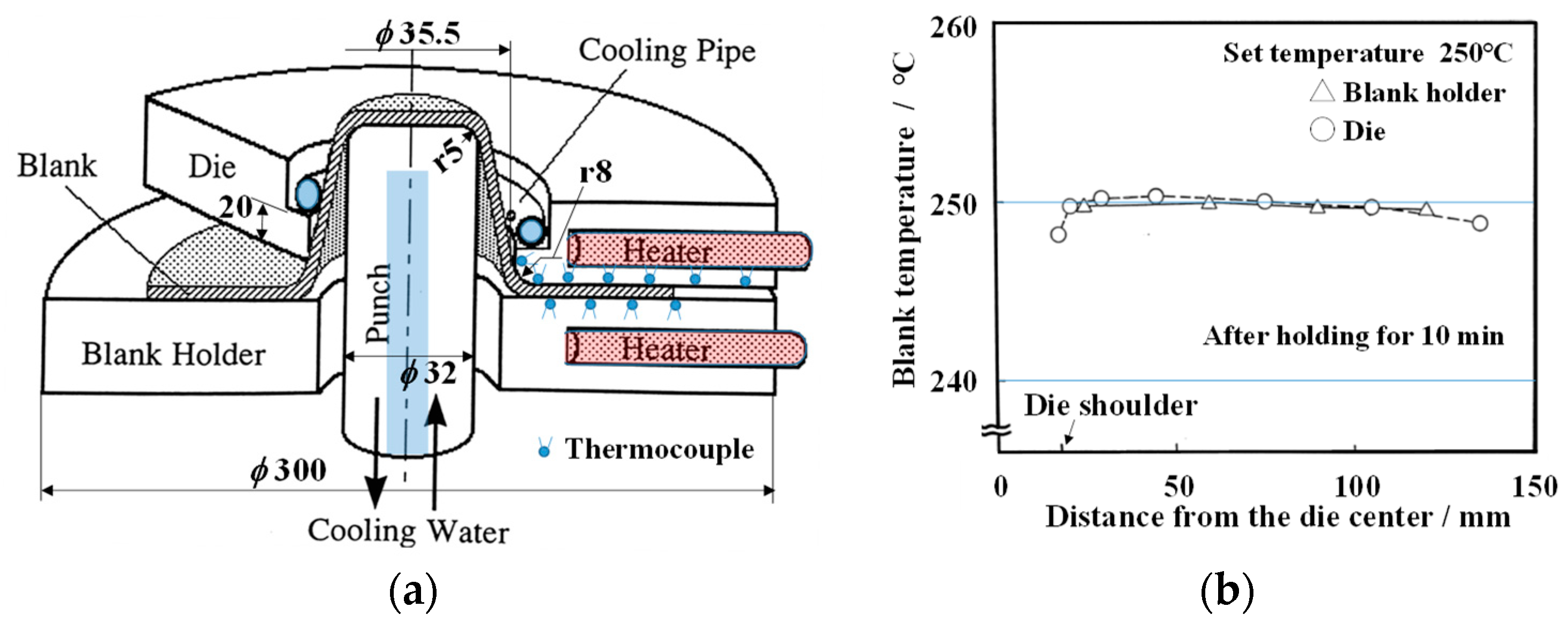
2.2. Experimental Equipment and Experimental Procedure

Figure 2 shows the schematic of tooling for warm cylindrical deep drawing and the temperature distribution of blank. The warm deep drawing apparatus was built into the Instron type universal testing machine and die tooling. In this deep drawing device, the BHF and SPD are feed-back controlled arbitrarily variable during the process under computer control, and the flange of the die is uniformly heated by six cartridge heaters for heating in warm forming. As shown in Figure 2b, the temperature distribution on the surface of the die and the blank holder after holding for 10 min was within ±1 °C after setting the blank. The temperature of the blank after setting the blank at a distance of 45 mm from the center became constant almost 2 min later. In the experiment, the blank holding time was set to 10 min with a margin. The punch was water-cooled from the inside of the punch, and additionally, the blank was cooled with compressed air (−25 °C) from the outside at the die outlet immediately after drawing into the die cavity. A spray type dry fluorine lubricant “Yunon S” (VALQUA, LTD., Tokyo, Japan) was used as the lubricant, and it was applied to both sides of the blank.
The temperature distribution on the both surfaces of the die and the blank holder was measured with a thermocouple at a total of 11 points (die: 7 points, blank holder: 4 points). The temperature at a point 45 mm away from the center of die reached the set temperature (250 °C) almost 2 min after the blank was set between the die and the blank holder and became constant. Regarding the temperature distribution on the surface of the die and the blank holder, it was confirmed that the temperature distribution on both surfaces was within ±1 °C after 10 min of blank setting. Therefore, in the experiment, the warm deep drawing experiment was started after blank holding for 5 min (DR = 3.1) and 10 min (DR = 5.0). Under the conditions of constant SPD and BHF, the deep drawing experiment was carried out under the following conditions, (1) SPD: 1, 10, 100, 200, 300, 400 mm/min; (2) BHF: 0.1, 0.5, 1.0, 2.0, 3.0, 5.0 kN. For the variable forming conditions, it was carried out within these ranges except for VBHF condition for DR = 5.
The occurrence and growth of flange wrinkles were observed and tracked by interrupting the deep drawing process for the drawing ratio DR = 5. To measure the wrinkle height of the flange portion, the drawn cup head was placed on the turntable so as to be on the upper side, and the flange portion was measured with a high-precision displacement meter. Based on a sample drawn at a punch speed of 100 mm/min, under which the maximum height of flange wrinkle is obtained, the measurement position of the flange wrinkle was adjusted to a position that does not exceed the measurement range of a precision displacement sensor. Wrinkle heights were measured at the same relative comparable positions.

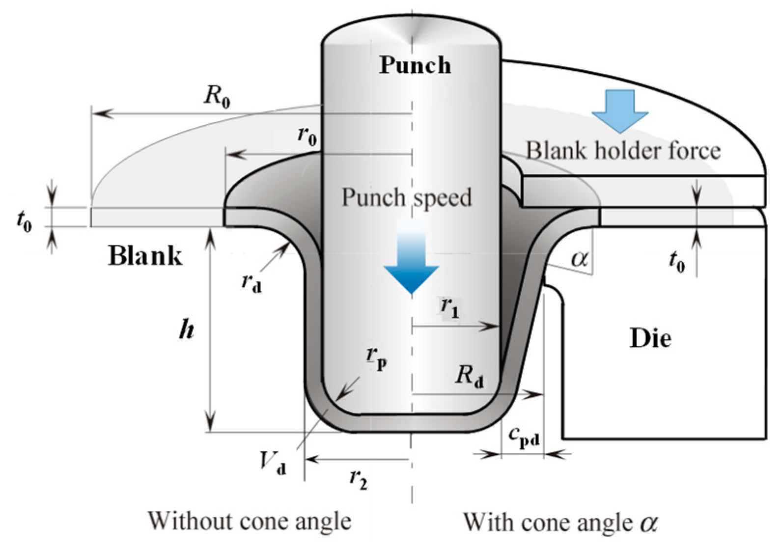
2.3. Analysis with Superplastic Deep Drawing Theory and Calculation Conditions

The basic theory of the VBHF and VSPD deep drawing for strain rate and strain hardening materials [23] is introduced in Appendix B. The theory is on the basis of deformation mechanics of the flange part. Analysis was performed to obtain theoretical support for the experimental results.
In order to obtain the theoretical solution of superplastic warm deep drawing, the material property and other input data on the processing conditions used for DR = 3.1 were as follows: K = 7.65 MPa, m = 0.32, n = 0.005, E = 90 GPa, σal = 14 MPa, R0 = 45 mm (DR = 2.5), t0 = 1 mm, r1 = 16.5 mm, r2 = 17.75 mm, rd = 8.5 mm, rp = 5.5 mm, ωcr = 0.00017, μ = 0.005 (see Appendix A—Nomenclature). Die and tooling dimensions are the same as those in the experimental setup.

3. Results and Discussion

3.1. Wrinkle Formation and Growth Behavior on the Flange Part for Large Blank DR = 5

Figure 3 shows a sequential photograph of the occurrence and growth of wrinkles on the flange in deep drawing under the conditions of constant SPD and BHF, with a warm deep drawing using a large blank with DR = 5. The amount of displacement at the flange end can be seen from the trace of mirroring of the die surface due to the flow from the initial blank state in which the dry-type fluorine lubricant is applied. At the early stage of deep drawing, fine streaky wrinkles occur near the entrance of the die, and then the wrinkles of a larger wavelength occur near the end of flange, which grows larger as the process progresses.
Figure 4 summarizes the effects of BHF and SPD on the occurrence of flange wrinkles under these conditions. Figure 4a shows the flange wrinkle limit lines under SPD = 1 mm/min. There are two types of wrinkle modes; the main wrinkle has large wavelength wrinkles near the flange rim, which can be observed after on the above third photograph in Figure 3. Another one is streaky wrinkles near the die inlet at the early stage, shown in the second photograph of Figure 3. Figure 4b shows the influence of the punch speed on the wrinkle limits and the “no wrinkle area”. For the large wavelength wrinkles, the higher the SPD, the larger the BHF required to suppress the occurrence of flange wrinkles. For the streaky wrinkles, the wrinkles occur easily in the case of large BHF conditions.
Originally, the BHF had the role of suppressing the occurrence of wrinkles. However, it has been shown that increasing the BHF has the opposite effect for streaky wrinkles for superplastic deep drawing with large blank (e.g., DR = 5).
In order to avoid the occurrence of large wavelength wrinkles even with superplastic materials and large blanks such as DR = 5, it can be experimentally confirmed that there is a possibility of a variable SPD method in which the BHF is increased as the process progresses. This is the same as the theoretical result obtained for warm deep drawing of aluminum alloy with DR = 3.1 [23].
Figure 5 shows the effect of the SPD on the height of wrinkles near the flange rim when the punch stroke h is 20 mm and the punch stroke is stopped halfway under BHF = 0.1 kN. As the SPD increases, the wrinkles grow larger, and the height of wrinkles increases. Here, looking at Figure 6 which compares the wall thickness distribution of the drawn product under the condition of 2 kN where the BHF is larger than the BHF condition of 0.1 kN in Figure 5, in the case that the BHF is larger at the same low speed of 1 mm/min as in Figure 5, the thickness of the outer peripheral region of the flange is strongly suppressed in the initial thickness state. However, the wall thickness is significantly reduced and extended from the vicinity of the die entrance to the cylindrical part toward the inside of the flange. It is presumed that streaky wrinkles due to tensile force are more likely to occur in this thinned portion because the wall thickness becomes thin and the BHF does not act. This is also shown in Figure 3, and it is the occurrence of wrinkles near the cylindrical part that are not the flange wrinkles on the outer edge of the flange, which are not shown in Figure 4.
Based on the above results, the effect of the variable pattern of the BHF was investigated experimentally. Figure 7 shows the effect of variable BHF patterns on the thickness distribution of a drawn cup for a blank with DR = 5. The BHF pattern is (1) the constant at 3 kN, (2) the linear increase BHF pattern from 3 kN to 11 kN, and (3) the linear decrease BHF pattern from 11 kN to 3 kN. In the case of the linear decrease BHF type method (3), the variable BHF effect is worst due to maximizing the thinning at the entire cylindrical part and the thickening at the flange end portion. From the results, it is clarified that the linear increase BHF pattern (2) improves the thickness distribution. Regarding the effect of VBHF on the wall thickness distribution, it was reported that the increasing BHF pattern is effective for uniforming the wall thickness distribution in a drawn cup [28,29]. This result reveals that the effect of increasing BHF is large in order to make wall thickness uniform over the entire area of the drawn product for large blank superplastic material. In this way, for superplastic materials, it is possible to achieve the warm deep drawing for a larger blank in one stroke processing, but for that case, the flange die surface is inevitably large, and the effect of BHF is sensitive and not uniform due to die accuracy, surface quality, friction/lubrication, non-uniformity of blank, etc. Thus, it becomes difficult to achieve stable warm deep drawing compared to warm deep drawing of conventional materials.

3.2. Experimental Fracture Limit and Wrinkle Limit of Warm Deep Drawing for Middle Size Blank DR = 3.1

The onset of fracture or thinning, which represents the forming limit of superplastic deep drawing, may be estimated from the geometric relationship between the punch stroke and the flange reduction displacement in the deep drawing process.
Figure 8 shows the relationships between the punch stroke h and ΔDR* for undesirable deformation during the process and the appearance of drawn cups with typical failure modes. In the Figure 8a, the result of the theoretical relation between the h and ΔDR* is also shown as “Theory” at the same time. For the experimentally successful deep drawing, the h increases almost linearly and smoothly with increasing ΔDR* and changes in the same way as the theoretical curve. However, when the side wall of the drawn cup becomes thin or fractures as shown in Figure 8b, the punch stroke increases rapidly (“onset” in the figure). The point of rapid increasing is also in agreement with the point to move away from the theoretical curve. It would be available to utilize the theoretical curve as a fracture determination method.
The theoretical curve between the h and ΔDR* can be derived from the volume constancy and the definition of the flange reduction ratio (A4) by the following equation.
h = 1 π ( V 0 V b V d ) + π t 0 { ( r 2 + r d ) 2 ( R 0 r 2 Δ DR * ) 2 } ( r 1 + t 0 ) 2 r 1 2 + r d + r p + t 0
where, V0 is an initial blank volume, Vb is a volume of the die inlet part, Vd is a volume of the punch radius part and the bottom disc part.
From the results, it is also conceivable to use the theoretical curve to monitor the stable deformation state and detect the forming defects in superplastic deep drawing process.
In addition, it can be confirmed from the shape of the remaining flange that the flange part draws in uniformly in the circumferential direction in this experiment with DR = 3.1.
Figure 9 shows the effects of BHF and SPD on the fracture limit obtained experimentally, which are determined on the basis of the above fracture determination method. The results imply that the larger the BHF, the earlier the fracture. It can be confirmed that the faster the SPD, the earlier the fracture. In the early stage of this process, it can be experimentally confirmed that the superplastic material with a large strain rate dependence is affected not only by the occurrence and growth of flange wrinkles but also by the fracture phenomenon. Furthermore, optimization of the temperature distribution by heating still remains a technical issue, but in the case of superplastic deep drawing conditions at constant SPD and BHF, at least it can be concluded that a low BHF (0.5 kN) and a low SPD (100 mm/min) are possible for this process.

3.3. Theoretical Fracture Limit and Wrinkle Limit of Warm Deep Drawing for Middle Size Blank

As described in Section 3.1, for DR = 5 with considerably large blank in a superplastic warm deep drawing, it is clarified that it is particularly difficult to obtain a successful drawn product with a uniform thickness, which also affects the wrinkling behavior. Thus, here the authors show the theoretical results of warm deep drawing using a blank with a smaller diameter, which makes it easier to obtain a more uniform thickness distribution.
Figure 10 shows the wrinkle limit BHF and fracture limit BHF for the warm superplastic deep drawing process with DR = 2.5 at different SPDs calculated from the simplified theory above. Compared to the previous studies by the authors who reported on SPCE steel sheet (m = 0.018) [27] and aluminum alloy A5182-O (m = 0.11, 300 °C) [23], the wrinkle limit and fracture limit BHFs curves for the superplastic material with a larger m value (0.32) are expected to be different.
Figure 10a shows the effect of punch speed on the wrinkle limit BHF line. The scale of the vertical axis is smaller than that of Figure 10b,c. The wrinkle limit curve becomes similar to a quadratic curve that increases as the process progresses, reaches a peak, and decreases. In the figure, a region below each curve represents “wrinkle” area where long wavelength wrinkles occur at the flange. In the case of constant BHF conditions, if the applied BHF path penetrates the wrinkle limit curve and its area, it means that flange wrinkles occur. Therefore, if a constant BHF is applied over the wrinkle limit curve, it will be a successful region, which means that wrinkles will not occur. As the punch speed increases, the limit line increases upward, and the slope of the limit curve becomes steeper at the initial stage of the process. From this figure, it can be seen that the faster the SPD and the lower the BHF, the earlier the wrinkle occurs. That means that in the constant BHF condition, it is essential to set the BHF to over a peak value of wrinkle limit curve. In the figure, when the punch speed is 232 mm/min, the wrinkle limit and the fracture limit curves are shown on the same figure, and the relationship between the two can be understood. From this, the magnitude of the effect of the punch speed on the both limit curves is significantly different.
Figure 10b shows the fracture limit BHF curve, which is featured that the fracture limit BHF decreases sharply at the initial stage of the processing, attains the minimum around ΔDR* = 0.01, and then increases. This can be clearly seen from Figure 10c of the enlarged view. The tendency of the fracture limit line to sharply decrease at the initial stage of process is in agreement with the experimental results in Figure 9a. Next, increasing the punch speed greatly lowers the fracture limit curve. From the enlarged view in Figure 10c, in the case of constant BHF conditions, for example, at BHF = 3 kN this process line does not intersect the fracture limit curve at SPD = 150 and 200 mm/min, but it comes to intersect with the fracture limit curves of 230 mm/min. This means that the fracture occurs after the start of the processing at the intersect point. When the punch speed is higher in this way, it intersects the fracture limit line at an earlier stage, so plotting the points on Figure 9b shows a tendency that is consistent with the experimental results (a decreasing line to the right). The wrinkle limit curve in Figure 10c at this time almost overlaps with the horizontal axis, so it is difficult to show the influence of the punch speed on the wrinkle limit curve on the same vertical axis scale as the fracture limit curve.
From the comparison of the experimental results in Figure 9a,b, it can be seen that the effects on the BHF and SPD on the wrinkle limit and fracture limit are qualitatively consistent with the actual tendency. However, the difference is still large quantitatively. In the calculation of fracture limit, the allowable stress at the die outlet was used as σal = 14 MPa, but this value greatly changes the order of the vertical axis of Figure 10b,c. It is also possible to position this value as a correction coefficient that matches the experimental results and correct it because the assumption of constant thickness does not satisfy, in particular, warm superplastic deep drawing of a larger DR blank.

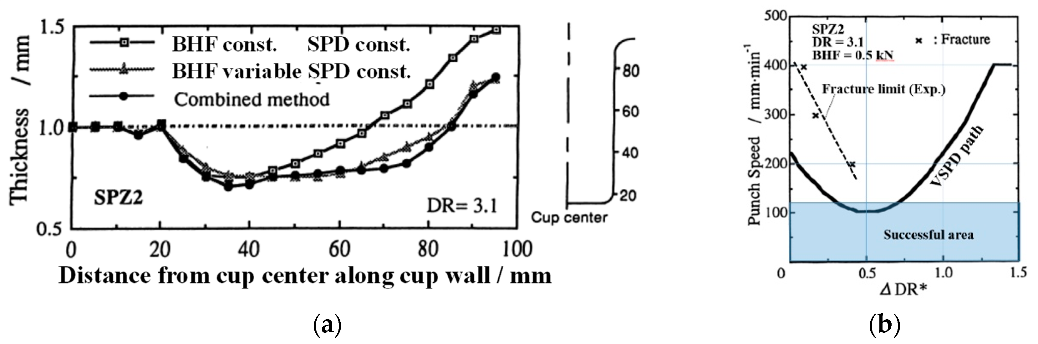
3.4. Verification of Effect of Variable BHF and SPD Methods in Warm Superplastic Deep Drawing

Figure 11 shows the schematic three-dimensional representation of fracture limit and wrinkle limit surfaces for the deep drawing process of strain rate and strain hardening-dependent material. This was constructed by arranging the BHF-ΔDR* diagrams of the fracture limit and wrinkle limit in the order of punch speed conditions in the three-dimensional depth direction.
The existence of each limit line in the late forming stage of the wrinkle limit and the fracture limit in this figure had already been experimentally verified by Kawai [30] first for the wrinkle limit and then by Manabe et al. [29] for the fracture limit. The method is to increase or decrease BHF stepwise from the successful region in the late forming stage.
According to the three-dimensional diagram of the fracture limit and the wrinkle limit, it is seen that there is a critical SPD (Vcr) in which both the fracture limit line and the wrinkle limit line are in contact with the constant BHF line at the same time under constant BHF conditions, or both limit lines are in contact with each other.
Since both limit lines intersect at two points in the region of SPD over Vcr, forming under constant SPD is no longer possible. However, a curve connecting the intersections at each SPD can be displayed. This is the “Critical variable BHF–SPD path” in the figure. By varying the punch speed during the process similar to this critical path, a new successful path exists in this region as shown by the thick line in the figure. As a result, processing at a higher SPD becomes possible, and it can be expected to be effective in shortening the processing time as well.
When this curve is projected onto a constant BHF plane, it can be expressed as a downwardly convex quadratic curve as shown in the upper part of the figure. The region inside this quadratic curve represents the fracture region. Therefore, it can be seen that even SPDs of Vcr or higher can be formed without fracture by varying the SPD during forming [23].
Here, the authors investigate the effect of m value on the wrinkle limit line and the fracture limit line in this three-dimensional space.
Figure 12 shows a contrast between the case of m = 0, which does not depend on the strain rate, and the both limit surfaces of a material having a larger m value such as a superplastic material.
When m = 0, both limit lines are not affected by the SPD, and the Vcr indicated in Figure 11 does not exist, so the VSPD scheme cannot be existed. As the m value increases, a space toward the success area is gradually created and expanded on the walls of the fracture limit surface on both sides in the figure. Therefore, new SPD and BHF spatial paths that pass through the successful space will appear.
Even in practical materials, the m value is low, but if Vcr is present, the effect of VSPD scheme can be expected and confirmed experimentally and analytically [27]. In particular, the superplastic materials with large strain rate dependence in Figure 12b have greater expectations. The possible paths of the VSPD method are shown in the figure.
To confirm the effect of this new processing method for superplastic material, first, Figure 13 shows the effect of VBHF method under constant SPD, compared with the thickness distribution of the constant BHF method. The VBHF pattern shown in Figure 13b was determined by referring to the experimental results and the calculation results in Figure 10b. At constant BHF condition, the thickness increases toward the flange rim, but with VBHF it can be improved more uniformly. It is confirmed that this effect is the same as that for the larger blank (DR = 5) in Figure 8.
Next, based on this VBHF effect, the effect of VSPD is examined. Figure 14 shows the VSPD effect on the thickness distribution when the VSPD is combined. The BHF and SPD routes of this combined variable method are indicated in Figure 13b and Figure 14b, respectively. The VSPD pattern in Figure 14b was determined by referring to the experimental results in the figure and the calculation results of the SPD effect in Figure 11 and Figure 12. It is seen that the thickness distribution in the combined method is almost the same as the result of VBHF condition, and it can be seen that the increase in thickness toward the flange end is suppressed.
Table 2 compares the processing times in different variable processing methods described in Figure 10 and Figure 11. The processing time of the conventional constant SPD and BHF conditions is 48 s, shortened to 29 s by the VSPD method, and its processing time can be reduced by 40%. Consequently, this combined VSPD/VBHF deep drawing for superplastic materials has a great contribution on the uniformity of the thickness distribution and on shortening the processing time.

4. Conclusions

  • Under constant forming conditions of the superplastic warm deep drawing experiment for SPZ2 with a larger blank, the flange wrinkle limit is affected by BHF and SPD. If the SPD is faster, the wrinkles with a large wavelength flange are likely to occur; the appropriate conditions of the BHF and SPD were low (BHF = 0.5 kN) and slow (SPD = 100 mm/min). When the BHF is larger, the wrinkles are likely to occur early, experimentally and theoretically. For the larger DR = 5, the wrinkle mode shifts to the streaky wrinkles near the die inlet with increasing BHF. In the case of lower punch speed with larger BHF conditions, the streaky wrinkles occur at the early stage.
  • For the VBHF and VSPD processes in which the variable pattern of BHF and SPD increases in the late stage, it is confirmed experimentally that the VBHF process exerted a significant effect on making the drawn cup uniform for DR = 5 and 3.1. The VSPD process has a great effect on shortening the processing time, and for DR = 3.1, the processing time was reduced by 40%.
  • The fracture limit and wrinkle limit based on the elementary theory are qualitatively consistent with the experimental results. It is important to understand the scope of the application of the theory and to use finite element analysis together for detailed deformation analysis.
  • It was confirmed that the VBHF/VSPD processes have the potential to greatly contribute to the improvement of formability, product quality, and processing time reduction as a superplastic forming process. Precise process sensing and control of material deformation in a highly accurate experimental environment are expected to increase its practical use and expand its applications.

Author Contributions

Conceptualization, K.-i.M.; investigation, K.S. and A.S.; validation, K.S. and A.S.; writing—original draft, K.S. and A.S.; writing—review and editing, K.-i.M.; supervision, K.-i.M. All authors have read and agreed to the published version of the manuscript.

Funding

This research was made possible by grant 20-69-46070 from the Russian Science Foundation.

Institutional Review Board Statement

Not applicable.

Acknowledgments

The authors are grateful to Tetsuya Yagami, the former PhD student at Tokyo Metropolitan University for his cooperation in the calculation.

Conflicts of Interest

The authors declare no conflict of interest.

Appendix A. Nomenclature

BHFblank holder force
DR = R0/r2 drawing ratio
DR* = r0/r2 current drawing ratio
ΔDR* = DR − DR* = (R0r0)/r2 flange reduction ratio
E 0 = 4 E F 0 / ( E + F 0 ) 2 reduced modulus
F 0 = K n ε ¯ ˙ e q m ( ε ¯ e q + 0.001 ) n 1 tangential modulus
Hblank holder force
Hcrfcritical blank holder force for fracture
Hcrwcritical blank holder force for flange wrinkle
hpunch stroke (drawn cup height)
Kstrength coefficient
mstrain rate sensitivity index
nstrain hardening exponent
SPD, v punch speed
Vcrcritical punch speed at constant punch speed condition
VBHFvariable blank holder force
VSPDvariable punch speed
αdie contact angle (inclination angle of cup wall)
β 0 = r 0 / r 2 (see Figure 1)
β i = ( r 2 + r d ) / r 2 (see Figure 1)
δ = 2 r 2 / t 0 relative die diameter
ε ¯ ˙ e q mean equivalent strain rate
μcoefficient of friction between blank and tool
ρd = rd/torelative die shoulder radius
σalallowable fracture stress of blank material
σ ¯ e q mean equivalent stress
σ i = 1.1 σ ¯ e q ln ( β 0 / β i ) ideal drawing stress
σddrawing stress
ωcrallowable specific wrinkle height

Appendix B. Theory of Warm Deep Drawing

Here, the theory of the VBHF and VSPD deep drawing for strain rate and strain hardening materials [23], which focused on deformation mechanics of the flange part, was introduced for the superplastic deep drawing process in this study.

Appendix B.1. Basic Equations for Warm Deep Drawing

Superplastic material is assumed to be homogeneous and isotropic. In this study, the authors employ a general constitutive equation that considers not only strain rate dependence but also strain hardening for superplastic characteristics and treats strain hardening extremely low in it. By doing so, the authors approximated and represented the constitutive equation, σ ¯ e q = K ε ¯ ˙ e q m , for a common superplasticity.
σ ¯ e q = K ε ¯ ˙ e q m ε ¯ e q n K ε ¯ ˙ e q m .
Assuming that the blank thickness remains constant during the deformation of circular cup deep drawing in Figure A1, and when the mean equivalent strain at flange part by Siebel is differentiated with respect to time and arranged [31], the mean equivalent strain rate at the flange part is expressed by the following equation, as a function of the punch speed v:
ε ¯ ˙ e q = 4 3 ( 1 r 0 r 2 3 r 0 r 2 3 r 0 2 2 r 0 r 2 4 R 0 2 r 2 2 ) r 2 r 0 v
Therefore, the constituent equation of superplastic material is written:
σ ¯ e q = K [ 4 3 ( 1 r 0 r 2 3 r 0 r 2 3 r 0 2 2 r 0 r 2 4 R 0 2 r 2 2 ) r 2 r 0 v ] m = σ ¯ e q ( r 0 , v )
A reduction ratio of the flange part, ΔDR*, is defined as a metric of forming a progress stage with the drawing ratio, DR = R0/r2, in this study.
Δ DR * = DR DR * = ( R 0 r 0 ) / r 2
Figure A1. Cylindrical cup deep drawing and notation.
Metals 11 00493 g0a1

Appendix B.2. Critical Wrinkle Limit BHF, Hcrw

Here, the theory of deep drawing for general materials with strain hardening and strain rate dependency is extended to a superplastic material. The critical wrinkle limit BHF can be expressed as the product of the effective contact area Af between flange die surface and blank and the critical wrinkle limit pressure pcr derived by Kawai [30].
H c r w = p c r A f = π { r 0 2 ( R d + r d ) 2 } E 0 ω c r 3.28 ( r 2 + r d r 2 ) 2 ( 2 r 2 t 0 ) ( R 0 r 2 ) ( R 0 r 2 ) 2 ( r 2 + r d r 2 ) 2 1 α B α H { ( σ i E 0 ) 2 4.77 ( r 2 + r d r 2 ) 2 ( 2 r 2 t 0 ) α B α D } 1 + ω c r μ { 3.82 ( r 2 + r d r 2 ) 2 ( 2 r 2 t 0 ) 2 ( R 0 r 2 ) } 1 α H σ i E 0
where
E 0 = 4 E F 0 / ( E + F 0 ) 2 , F 0 = K n ε ¯ ˙ e q m ( ε ¯ e q + 0.001 ) n 1 , α H = β 0 + β i , δ = 2 r 2 / t 0 , σ i = 1.1 σ ¯ e q ln [ β 0 β i ] , α B = β 0 + β i β 0 β i , α D = ( β 0 + β i ) 2 ( β 0 β i ) 3 , β 0 = r 0 r 2 , β i = r 2 + r d r 2
substituting the constitutive Equation (A1) of the superplastic material into the ideal drawing stress σ i of the Equation (A5); since this σ i is a function of the mean equivalent stress σ ¯ e q , the theoretical critical wrinkle limit BHF can be calculated for the superplastic deep drawing. The critical wrinkle limit formula gives the minimum required wrinkle suppression pressure that causes allowable specific wrinkle height ω c r .

Appendix B.3. Critical Fracture Limit BHF, Hcrf

The following drawing stress formula was used in consideration of bending and unbending at the shoulder of the die:
σ d = ( 1 + μ α ) { 1.1 σ ¯ e q ln ( DR * ) + μ δ H 2 π r 2 2 ( DR * ) + t 0 4 ρ d σ ¯ e q } + t 0 4 ρ d σ ¯ e q
Here, α is the inclination angle (die contact angle) of drawn cup wall in Figure A1, and the following equation can be obtained from the geometrical relationship:
α = cos 1 B + ( B 2 4 AC ) 1 / 2 2 A
Here,
A = ( h r p r d c p d + r p + r d ) 2 + 1 , B = 2 ( r p + r d ) ( h r p r d ) ( c p d + r p + r d ) 2 , C = ( r p + r d c p d + r p + r d ) 2 1
From the above, the critical fracture limit BHF, Hcrf, can be expressed by the following equation:
H c r f = 2 π r 2 2 ( DR * ) μ δ { 4 ρ d σ a l σ ¯ e q t 0 4 ρ d ( 1 + μ α ) 1.1 σ ¯ e q ln ( DR * ) t 0 4 ρ d σ ¯ e q }

References

  1. Japanese Standards Association. Glossary of Terms Used in Metallic Superplastic Materials; JIS H7007:2002 No.1001; Japanese Standards Association: Tokyo, Japan.
  2. Ohsawa, H.; Saito, T.; Ikeda, H.; Nishimura, H.; Miyagawa, M. High speed deep drawing of Zn-Al alloy superplastic sheet (2nd report). In Proceedings of the 1977 Japanese Spring Conference on Technology of Plasticity, Tokyo, Japan, 31 May–2 June 1977; pp. 499–502. [Google Scholar]
  3. Yoshihara, S.; Nishimura, H.; Yamamoto, H.; Manabe, K. Formability enhancement in magnesium alloy stamping using a local heating and cooling technique: Circular cup deep drawing process. J. Mater. Process. Technol. 2003, 142, 609–613. [Google Scholar] [CrossRef]
  4. Manabe, K.; Nishimura, H.; Hamano, H. An Improvement in Deep Drawability of Steel/Plastic Laminate Sheets by Control of Blank Holding Force. Proceedings the Second International Conference on Technology of Plasticity, Stuttgart, Germany, 24 August 1987; pp. 1297–1304. [Google Scholar]
  5. Murata, A.; Ebine, Y.; Matsui, M. Effect of Blank Holding Force Control on Deep Drawability of Square Shell. J. Jpn. Soc. Tech. Plast. 1992, 33, 411–416. [Google Scholar]
  6. Ahmetoglu, M.; Coremans, G.L.; Kinzei, G.L.; Altan, T. Improving Drawability by Using Variable Blank Holder Force and Pressure in Deep Drawing of Round and Non-Symmetric Parts. Soc. Automot. Eng. Tech. 1993, 113–120. [Google Scholar]
  7. Hirose, Y.; Kojima, M.; Ujihara, S.; Hishida, Y. Development of Forming Technique with Real-Time Control of Blank Holding Force. In Proceedings of the 17th Biennial Congress of the IDDRG, Shenyang and Beijing, China, 11–13 June 1992; pp. 300–308. [Google Scholar]
  8. Manabe, K.; Koyama, H. Intelligent Control Scheme of Divided Blank Holder for Square–Cup Deep-Drawing Process. Int. J. Mater. Product Technol. 2008, 32, 476–490. [Google Scholar] [CrossRef]
  9. Koyama, H.; Wagoner, R.H.; Manabe, K. Blank Holding Force Control in Panel Stamping Process Using a Database and FEM Assisted Intelligent Press Control System. J. Mater. Process. Technol. 2004, 152, 190–196. [Google Scholar] [CrossRef]
  10. Yixiong, F.; Zhifeng, Z.; Guangdong, T.; Zhihan, L.; Shaoxu, T.; Hongfei, J. Data-driven accurate design of variable blank holder force in sheet forming under interval uncertainty using sequential approximate multi-objective optimization. Future Gener. Comput. Syst. 2018, 86, 1242–1250. [Google Scholar]
  11. Kitayama, S.; Natsume, S.; Yamazaki, K.; Han, J.; Uchida, H. Numerical investigation and optimization of pulsating and variable blankholder force for identification of formability window for deep drawing of cylindrical cup. Int. J. Adv. Manuf. Technol. 2016, 82, 583–593. [Google Scholar] [CrossRef]
  12. Lin, Z.; Wang, W.; Chen, G. A new strategy to optimize variable blank holder force towards improving the forming limits of aluminum sheet metal forming. J. Mater. Process. Technol. 2007, 183, 339–346. [Google Scholar]
  13. Wang, L.; Lee, T.C. Controlled strain path forming process with space variant blank holder force using RSM method. J. Mater. Process. Technol. 2005, 167, 447–455. [Google Scholar] [CrossRef]
  14. Kergen, R.; Jodogne, P. Computerized Control of Blank Holder Pressure on Deep Drawing Presses. In Proceedings of the International Congress and Exposition, SAE Technical Papers Series, Detroit, MI, USA, 24–28 February 1992; pp. 51–56. [Google Scholar]
  15. Sim, H.B.; Boyce, M.C. FEM Anaysis of Real-Time Stability Control in Sheet Forming Process. Trans. ASME J. Eng. Mater. Technol. 1992, 114, 18–188. [Google Scholar] [CrossRef]
  16. Siegert, K.; Zielgler, M.; Wagner, S. Closed Loop Control of the Friction Force. Deep Drawing Process. J. Mater. Process. Technol. 1997, 71, 126–133. [Google Scholar] [CrossRef]
  17. Yagami, T.; Manabe, K.; Yang, M.; Koyama, H. Intelligent Sheet Stamping Process Using Segment Blank Holder Modules. J. Mater. Process. Technol. 2004, 155–156, 2099–2105. [Google Scholar] [CrossRef]
  18. Hongsheng, Z.; Siji, Q.; Liqin, C.; Linyuan, M.; Qianrong, Z.; Chuang, L. Research on Deep Drawing Process Using Radial Segmental Blank Holder based on Electro-permanent Magnet Technology. J. Manuf. Process. 2020, 59, 636–648. [Google Scholar]
  19. Benny, E.; Søren, T.; Joachim, D. A novel feedback control system—Controlling the material flow in deep drawing using distributed blank-holder force. J. Mater. Process. Technol. 2013, 213, 36–50. [Google Scholar]
  20. Koyama, H.; Manabe, K. Virtual Processing in Intelligent BHF Control Deep Drawing of Sheet Metal. J. Mater. Process. Technol. 2003, 143–144, 261–265. [Google Scholar] [CrossRef]
  21. Sheng, Z.Q.; Jirathearanat, S.; Altan, T. Adaptive FEM simulation for prediction of variable blank holder force in conical cup drawing. Int. J. Mach. Tools Manuf. 2004, 44, 487–494. [Google Scholar] [CrossRef]
  22. Marek, H.; Jakob, W.; Jens-Peter, M. Optimisation of deep drawn paperboard structures by adaptation of the blank holder force trajectory. J. Mater. Process. Technol. 2016, 232, 142–152. [Google Scholar]
  23. Manabe, K.; Yoshihara, S.; Nishimura, H.; Shibata, A. Theoretical analysis of punch speed and blank holding force control in deep drawing process of strain-rate-sensitive materials. In Proceedings of the ASME Dynamics Systems and Control Division ASME, Atlanta, GA, USA, 17–22 November; pp. 175–182.
  24. Yoshihara, S.; Koyama, H.; Manabe, K. Database-Oriented Adaptive Punch Speed Control of Sheet Stamping Process Using Fuzzy Logic. In Intelligence in a Materials World (Selected Papers from IPMM2001); CRC Press: Cleveland Heights, OH, USA, 2003; pp. 763–769. [Google Scholar]
  25. Manabe, K.; Koyama, H.; Yoshihara, S.; Yagami, T. Development of a Combination Punch-Speed and Blank-Holder Control System for the Deep Drawing Process. J. Mater. Process. Technol. 2002, 125–126, 440–445. [Google Scholar] [CrossRef]
  26. Manabe, K.; Yagami, T.; Yoshihara, S.; Koyama, H. An Intelligent Process Control of Punch Speed and Blank Holder Force in Deep Drawing. In Proceedings of the 22nd Biennial Congress of the IDDRG2002, Nagoya, Japan, 20–22 May 2002; pp. 185–192. [Google Scholar]
  27. Yagami, T.; Manabe, K. FE Analysis on Deformation Mechanism of Strain-Rate-Sensitive Materials in Cylindrical Deep-Drawing with Combination Punch Speed and Blank Holder Control. J. Solid Mech. Mater. Eng. 2007, 1, 1385–1396. [Google Scholar] [CrossRef] [Green Version]
  28. Manabe, K.; Yoshihara, S.; Yang, M.; Nishimura, H. Optimization of the Variable BHF Deep-Drawing Process by Fuzzy Model. J. JSTP 1995, 36, 1015–1022. [Google Scholar]
  29. Manabe, K.; Hamano, J.; Nishimura, H. A New Variable Blank Holding Force Method in Deep Drawing of Sheet Materials. J. JSTP 1988, 29, 740–747. [Google Scholar]
  30. Kawai, N. Critical Conditions of Wrinkling in Deep Drawing of Sheet Metals—Reports 1,2 and 3. Bull. JSME 1961, 4, 169–192. [Google Scholar] [CrossRef]
  31. Siebel, E. Der Niederhalterdrunk beim Tiefzien. Stahl Und Eisen 1954, 74, 155–158. [Google Scholar]
Figure 1. Tensile test of the used material (a) specimen (unit: mm) and (b) stress–strain curves at different tensile speeds.
Metals 11 00493 g001
Figure 2. Schematic of tooling for warm cylindrical deep drawing and temperature distribution of the blank. (a) Schematic warm deep drawing tooling (unit: mm), (b) temperature distribution of the blank.
Metals 11 00493 g002
Figure 3. A sequential photograph of the occurrence and growth of wrinkles on the flange part under the conditions of constant punch speed (SPD) and blank holder force (BHF) in a warm deep drawing process using a large blank with a drawing ratio (DR) = 5.
Metals 11 00493 g003
Figure 4. Effects of BHF and SPD on the occurrence of flange wrinkles under constant BHF and SPD in warm superplastic deep drawing (DR = 5). 〇: SPD (mm/min) = 1, ◇: SPD = 10, △: SPD = 100, solid line: large wavelength wrinkle mode, dashed line: streaky wrinkle mode. (a) Wrinkle limit diagram at SPD=1 mm/min; (b) effect of SPD on wrinkle limit diagram.
Metals 11 00493 g004
Figure 5. Effect of punch speed on the long wavelength wrinkle height on the flange end part under BHF = 0.1 kN and punch stroke = 20 mm (DR = 5.0).
Metals 11 00493 g005
Figure 6. Comparison of wall thickness distribution of drawn cup at punch stroke of 60 mm under different SPDs (BHF = 2 kN, DR = 5.0). Left: thickness distribution. Right: measuring points on the drawn cup.
Metals 11 00493 g006
Figure 7. Comparison of thickness distribution of a drawn cup at a punch stroke of 60 mm under different BHF patterns (DR = 5.0).
Metals 11 00493 g007
Figure 8. Determination method of the onset point of failure modes in warm superplastic deep drawing and the typical samples of drawn cups (DR = 3.1). (a) Punch stroke-ΔDR* diagram, (b) failure modes of drawn cup samples. Left: thinning. Center: success (100 mm/min, 0.5 kN). Right: fracture.
Metals 11 00493 g008
Figure 9. Effects of BHF and SPD on the fracture limit obtained in the warm superplastic deep drawing experiment (DR = 3.1). (a) Fracture limit BHF, (b) fracture limit SPD.
Metals 11 00493 g009
Figure 10. Theoretical wrinkle limit and fracture limit diagram for the superplastic warm deep drawing process. (a) Wrinkle limit BHF, (b) fracture limit BHF, (c) fracture limit BHF (enlarged view).
Metals 11 00493 g010
Figure 11. Schematic concept of critical variable BHF and SPD method in three dimensional BHF–SPD–ΔDR* space for warm deep drawing of strain rate-dependent materials. Vcr: critical punch speed at constant punch speed condition.
Metals 11 00493 g011
Figure 12. Conceptual three-dimensional representation of the flange wrinkle limit and fracture limit in warm deep drawing process of strain rate dependent material. (a) No strain rate-dependent material. No gateway to successful processing space. (b) High strain rate-dependent material (superplastic material, appearance of gateway region to successful processing space).
Metals 11 00493 g012
Figure 13. Comparison of thickness distribution of drawn cup by different BHF conditions. (a) Thickness distribution, (b) variable blank holder force (VBHF) path.
Metals 11 00493 g013
Figure 14. Comparison of thickness distributions of drawn cup for different processing paths (DR = 3.1). (a) Thickness distribution, (b) variable punch speed (VSPD) path and the same VBHF path as Figure 14b.
Metals 11 00493 g014
Table 1. Mechanical properties of used material.
Temperature/°CK/MPamnStrain RangeStrain Rate Range
2507.650.320.00510−2 < ε < 12 × 10−2 < ε ˙ < 3 × 10⁻¹
Table 2. Forming time for different variable processing methods (DR = 3.1, punch stroke = 80 mm).
ProcessForming Time/sTime Reduction Rate, %
Constant punch speed method
(at successful limiting punch speed)
48-
Variable punch speed method29Δ40
Combined method29Δ40
Publisher’s Note: MDPI stays neutral with regard to jurisdictional claims in published maps and institutional affiliations.

