Article

Numerical Modeling of Plasticity-Induced Fatigue Crack Growth Retardation Due to Deflection in the Near-Tip Area

Fracture & Structural Integrity Research Group (FSIRG), University of Salamanca (USAL), E.P.S., Campus Viriato, Avda. Requejo 33, 49022 Zamora, Spain
*
Author to whom correspondence should be addressed.
Metals 2021, 11(4), 541; https://doi.org/10.3390/met11040541
Submission received: 31 January 2021 / Revised: 22 March 2021 / Accepted: 22 March 2021 / Published: 26 March 2021
(This article belongs to the Special Issue Advanced Characterisation of Fatigue Behaviour in Metal Alloys)

Abstract

:
This article studies the retardation effect in plasticity-induced fatigue crack growth rate for a low-medium strength steel, due to the appearance of microdeflections in the crack path. To this end, the finite element method was used to model the crack with its kinked tip under several stress intensity factor (SIF) ranges. The results allowed a calculation (after a small number of cycles) of the fatigue crack propagation rate for the multiaxial and uniaxial fatigue configurations at the microscopic level. It was observed that the retardation effect rose with an increase in the initial kinked crack tip angle, an increase in the initial projected kinked crack tip length, and with a decrease in the SIF range.

1. Introduction

During fatigue propagation (in mode I), at the microscopic level, the crack presents multiple deflections and bifurcations produced by the microstructure of the material [1]. The non-linear crack configuration (bent, curved, and branched cracks) should be taken into account in the matter of crack-morphological aspects in fracture mechanics [2]. Thus, the crack deflection induces changes in the propagation rates that are discussed in terms of the local mode of crack advance, effective driving force, microstructure, etc. [3].
Elastic-plastic finite element simulations of growing fatigue cracks are used to study the plastic crack advance and the so-called crack closure phenomenon (if it really did exist). The fatigue propagation happens following the Laird-Smith physical concept [4] of fatigue cracking by plastic blunting and re-sharpening (one of the well accepted mechanisms of fatigue crack growth), material transfer appearing from the apex vicinity tip to the formed crack flanks, with rotation and stretching of elements along the crack faces [5,6]. The simulation in single crystals [7] predicts the dependence of the fatigue striation formation on the crack growth direction (obtained by experimental results).
Calculations of the advance rate per cycle reproduce the common trends of the fatigue cracking dependence on loading range and overload, where the crack growth slows after the overload cycles [8]; as well as the fact that a compressive underload cycle and periodic underloads tend to increase the crack cyclic propagation rate [9]. The simulated fatigue crack growth for constant amplitude loading complies with the Paris law and shows a typical R-ratio dependence [10]. These calculations allowed to obtain the Paris equation of high-strength steels, in good harmony with experimental results [11].
In relation to the plasticity-induced fatigue crack closure, a strong and long-standing scientific debate does exist with opposite positions between research groups. In Reference [12], it is stated that crack closure occurs under pure plane strain conditions, although the total length of the closed crack at minimum load is shown to be a small fraction of the total crack length, especially for the positive stress ratios, thereby making it extremely difficult to measure. In [13], it was observed that the crack-tip opening displacement (CTOD) typically underwent a transient behavior, with no crack closure during many cycles, before a steady-state cycling with crack closure at the tip started to gradually develop. In [5,6,8,10], it was maintained that the plasticity induced crack closure did not appear, so the supposed consequences of this phenomenon on the fatigue crack growth (experimental evidence of overload retardation and compressive residual stress effects) appeared without any need of plasticity-induced crack closure.
The discrepancies in the results with respect to the crack closure could be associated with the use of diverse finite elements, remeshing techniques, loading ranges, and number of load cycles applied [7]. Large-deformation elastoplastic finite element simulations of the crack under cyclic loading evidenced a notorious mesh sensitivity, which begins at the spontaneous shear localization [14]. Assuming that folding at the crack surface is very sensitive to geometrical imperfections, differences in the method used to generate the mesh might also be the reason why folding do not always appear on the crack surfaces, neither in the first cycles nor in subsequent cycles [15].
The stress intensity factor (SIF) of kinked cracks was calculated by several authors [16,17]. The modeling of crack morphology as a periodically kinked path (periodically-kinked crack model) showed a decrease of the fatigue crack growth rate in the Paris range, as the kinking angle increased [18]. The overload retardation effect was, in part, due to the appearance of crack micro-roughness and branching, so the application of a single tensile overload could kink or fork the pre-overload crack [19].
The main aim of this research work was to study the retardation in plasticity-induced fatigue crack growth, due to the microdeflection in the near tip area for a low-medium strength steel. The key variables analyzed were—initial crack tip angle in relation to the main crack, initial projected crack tip length in the direction of the macroscopic crack length, and the SIF range.

2. Numerical Procedure

With the purpose of studying the fatigue propagation through plastic crack advance, a numerical simulation by the finite element method (FEM) under small scale yielding (SSY) was performed using the MSC Marc software (nonlinear finite element code). Material was characterized as elastic/perfectly-plastic and the von Mises yield criterion was used to define the plastic zone in the vicinity of the crack tip. Large strains and large geometry changes were considered with an updated Lagrangian formulation.
The material properties were Young’s modulus E = 200 GPa, Poisson coefficient ν = 0.3 and effective yield strength σY = 300 MPa (associated with low-medium strength steel). The effective yield strength corresponded to some saturation stress level (given by strain-hardening), not to the initial yield point in a tensile test [5].
The modeling consisted of a symmetric double-edge-cracked panel subjected to remote tension cyclic loading (Figure 1a). The undeformed crack (initial crack) was a parallel-flanks slot with width b0, where the length of the final part (Figure 1b) was deflected at an angle α0 in relation to the main crack length (kinked crack tip).
The projected length of this initial deflected tip is called l0’. The crack end presents a semicircular geometry (smooth blunting [20]), so the crack was treated as a sharp notch with a small (but not zero) radius, avoiding the physically unrealistic singularity at its tip [21]. The plate width (2 W) was equal to its height and the crack length (a0) was 0.2 times the plate half-width (a0 = 0.2 W) and 15,000 times the crack width (a0 = 15,000 b0).
One half of the problem was modeled (Figure 2a) with the necessary boundary conditions to simulate the symmetry of the problem. In relation to the finite element mesh size (Figure 2b), the sides of the smallest near-tip elements were about 0.04 b0 [5]. Full-integration bi-linear four-node isoparametric quadrilateral elements (for plane strain applications) were used.

3. Fatigue Propagation Curve
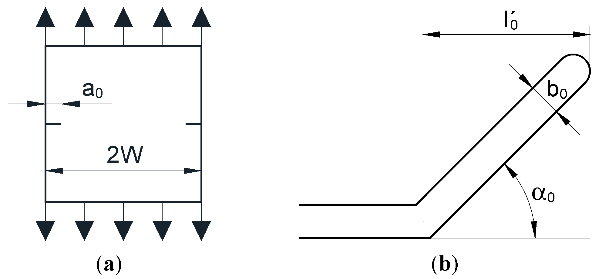
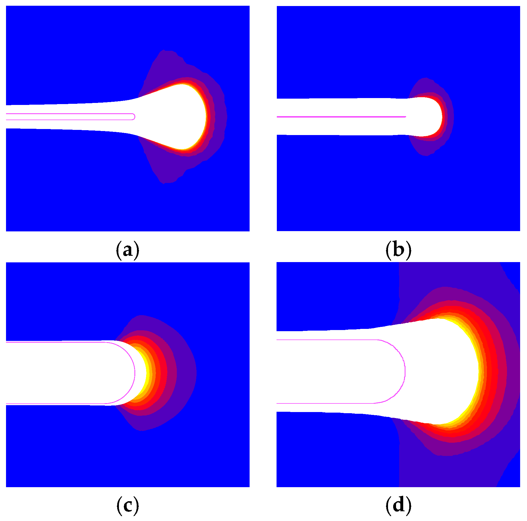
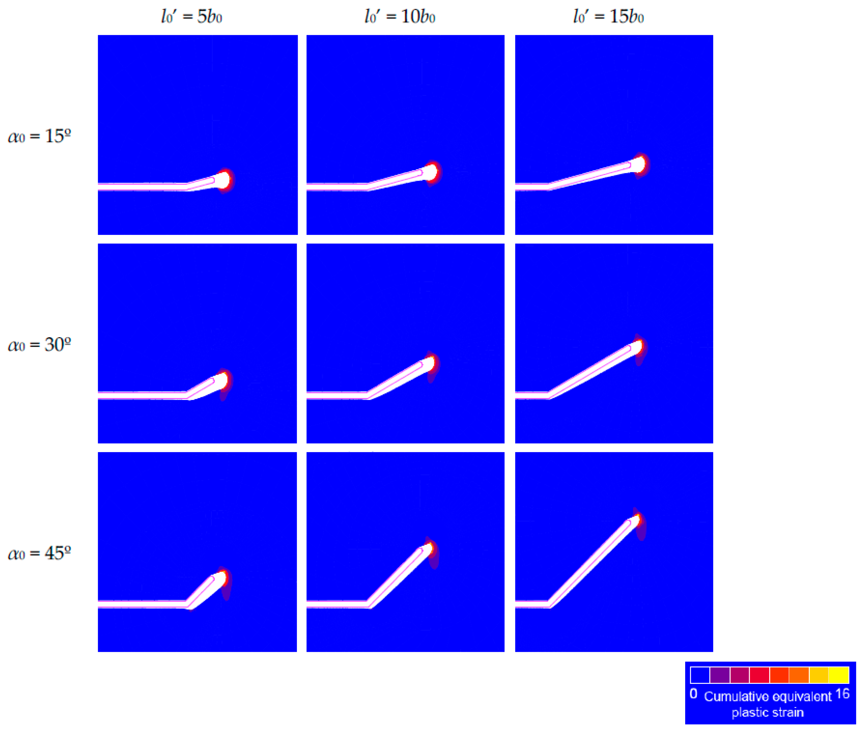
In a material with certain mechanical properties (E, υ, σY) containing a slot under fatigue in mode I, the plastic fatigue growth rate depended on the notch width b0 and the stress level, for a given geometry. When the deformations were quite large compared to the notch width (i.e., when the SIF range ΔK was sufficiently high), a stress-deformation field was formed at the tip of the notch that approached an autonomous (self-similar) configuration. When this occurs, the afore-said notch could be considered as a crack in terms of the applicability of fracture mechanics tools, and below this width, notches of different widths behave in the same way (like a crack).
It was found that under monotonic loading, the notch could be treated as a crack when the corresponding CTOD δt is [22,23]:
δ t = β K I 2 E σ Y 2 b 0 ,
where KI is the SIF and β is a coefficient obtained from elastoplastic simulations [22,23].
Under cyclic loading, this matter was much more complicated, because the evolution of the stress-deformation field during each load cycle depended not-only on the initial geometry, but also on what happened in each previous load cycle (the effect of residual stresses after each loading cycle, stress-deformation paths in plasticity, etc.), i.e., on the mechanical loading history.
For the studied material, the plot representing crack growth Δa versus number of cycles N was obtained using the symmetric double-edge-cracked panel under a remote tension cyclic loading, with the totally smooth crack (unkinked crack) for several crack widths b0 = 0.5, 1, 5, 10, and 50 μm and SIF ranges ΔK = 25 and 50 MPam1/2 (Figure 3). The crack growth Δa corresponded to the displacement (in the direction of the initial macroscopic crack for global mode I) of the material point of the crack end. For the calculations, a single mesh conveniently scaled was used, considering the change in crack size, to calculate the loading that should be applied. The Δa-N curves could be slightly curved (instead of perfect straight lines), in agreement with other simulations [12].
In this case study, for a symmetric double-edge-cracked panel with a0 = 0.2 W, subjected to remote tension loading, the expression to calculate the SIF was [24]:
K I = 1.158 σ π a 0 ,
where σ was the applied remote stress (the small crack growth Δa was not taken into account to obtain the SIF KI).
For the modeling, the crack was advanced by cyclic blunting and re-sharpening (Laird-Smith mechanism), which transferred material from the crack tip towards its flanks; whereas the crack closure was never achieved [5,6,7]. Figure 4 shows the cumulative equivalent plastic strain in the deformed geometry of the cracked solid (crack tip) after applying 20 loading cycles. The initial geometry of the solid before loading (initial crack profile) was also depicted. The cumulative equivalent plastic strain εpcum (one of the key variables commonly used to characterize the strains in fatigue, a mechanical variable able to monitor the fatigue damage accumulation [25]), was defined as:
ε cum p = ( 2 3 d ε ij p d ε i j p ) 1 / 2 ,
where εijp are the components of the plastic strain tensor. The integration for calculating the cumulative equivalent plastic strain was performed along the loading history.
Deformed crack tips usually acquire a keyhole shape after unloading (Figure 4a), as the cracks shrink in a wake behind the tip rather than at the tip itself [5,6,8,26]. When a SIF range ΔK = 50 MPam1/2 was applied, fatigue crack growth was lower for the smaller crack widths (b0 = 0.5 and 1 μm) due to the appearance of an excessive deformation in the crack tip (Figure 4b). For ΔK = 25 MPam1/2 with the biggest crack width (b0 = 50 μm), the curve of fatigue crack growth vs. number of cycles exhibited a very curved appearance with a growth after the 20 load cycles lower than the rest of the calculations, because the deformation accumulated only in a part of the crack end (Figure 4c). It did not happen when ΔK = 50 MPam1/2 was applied with the greatest crack width (Figure 4d).
In view of the results of Figure 3 and Figure 4, for the remaining calculations, the initial crack width b0 = 5 μm was used for this low-medium strength steel, looking for a small enough crack width, thereby promoting SIF control over the analyzed problem.
The fatigue propagation curve (da/dN)0K (fatigue crack growth rate vs. SIF range) for the material studied in the Paris regime was obtained from the symmetric double-edge-cracked panel, under remote tension fatigue with the totally smooth crack, by the adjustment of several points (Figure 5).
These corresponded to the propagation rate generated by a plastic flow (average value measured after applying 20 loading cycles) of the crack located in the panel subjected to several SIF ranges (including ΔK = 25, 37.5, and 50 MPam1/2). The results (Figure 5) exhibited an excellent agreement with a potential curve that could be easily associated with a Paris law [27]:
( d a d N ) 0 = C Δ K m .
Thus, allowing an estimation of the Paris parameters of the material (C and m).

4. Kinked Crack Tip

This study on the effect of the crack tip microdeflection on fatigue growth showed how, independent of the deflection angle, the crack tended to propagate in mode I when the plate was subjected to remote mode I (opening) tensile loading. In addition, the local crack tip deflection provoked a retardation effect in the fatigue crack growth rate in global mode I [28]. This phenomenon was characterized by the retardation factor (da/dN)/(da/dN)0, where (da/dN)0 was the fatigue crack growth rate for the straight tip, and (da/dN) was the fatigue crack growth rate for the kinked tip, both associated with the mean value evaluated after applying on the sample of 20 loading cycles.
In Figure 6, the retardation factor (da/dN)/(da/dN)0 for the kinked crack tip was represented against the initial crack tip deflection angle (α0 = 15°, 30°, and 45°) for several initial projected crack tip length (l0’ = 25, 50, and 75 μm). The SIF ranges (fatigue intensities) in the numerical procedure were ΔK = 25, 37.5, and 50 MPam1/2 (associated with the Paris regime of fatigue crack propagation) and the material was a low-medium strength steel (σY = 300 MPa).
The results showed how the retardation effect rose (and thus, the retardation factor descended) with a decrease in the SIF range ΔK, and with an increase in the initial kinked crack tip angle α0 and of the initial projected kinked crack tip length l0’.
Previous research by the authors [1] showed that there was a decrease in the crack propagation rate by increasing the microscopic angle of fatigue crack tortuosity, the value of this micro-angle being related to the microstructure of the material. In addition, it was also proved that the SIF range increased the micro-roughness of the fatigue profile path because the length in-between microdeflections was higher, cf. [1].
Figure 7 and Figure 8 show the cumulative equivalent plastic strain distributions in the deformed geometry of the cracked solid (kinked crack tip) after applying 20 loading cycles. The initial geometry of the solid before loading (initial crack profile) was also depicted in them. These pictures were for ΔK = 25 and 50 MPam1/2, since the differences between the obtained results were greater. The distribution of cumulative equivalent plastic strain became more non-symmetric and exhibited more elevated values, as the initial crack tip deflection angle rose. Figure 9 shows the final kinked crack tip angle αf (in relation to the main crack length), after 20 loading cycles for ΔK = 25, 37.5, and 50 MPam1/2. In Figure 10, the maximum crack opening displacement (COD) in the kinked crack tip was depicted after 20 loading cycles (COD was not constant in the crack branch). As the SIF range (fatigue intensity) increased and the initial projected kinked crack tip length decreased, the retardation effect was reduced. This could be associated to the fact that the deformation produced a greater diminishment in the angle of the propagated deflected crack tip, with respect to the initial deflected crack tip, and also caused a higher COD in the region of the deflected crack tip. Variations in COD were observed in the kinked cracks obtained in steels subjected to a cyclic load [1].

5. Conclusions

The following conclusions could be drawn about the retardation effect produced by the deflection in the vicinity of the crack tip on the plasticity-induced fatigue crack growth:
(i)
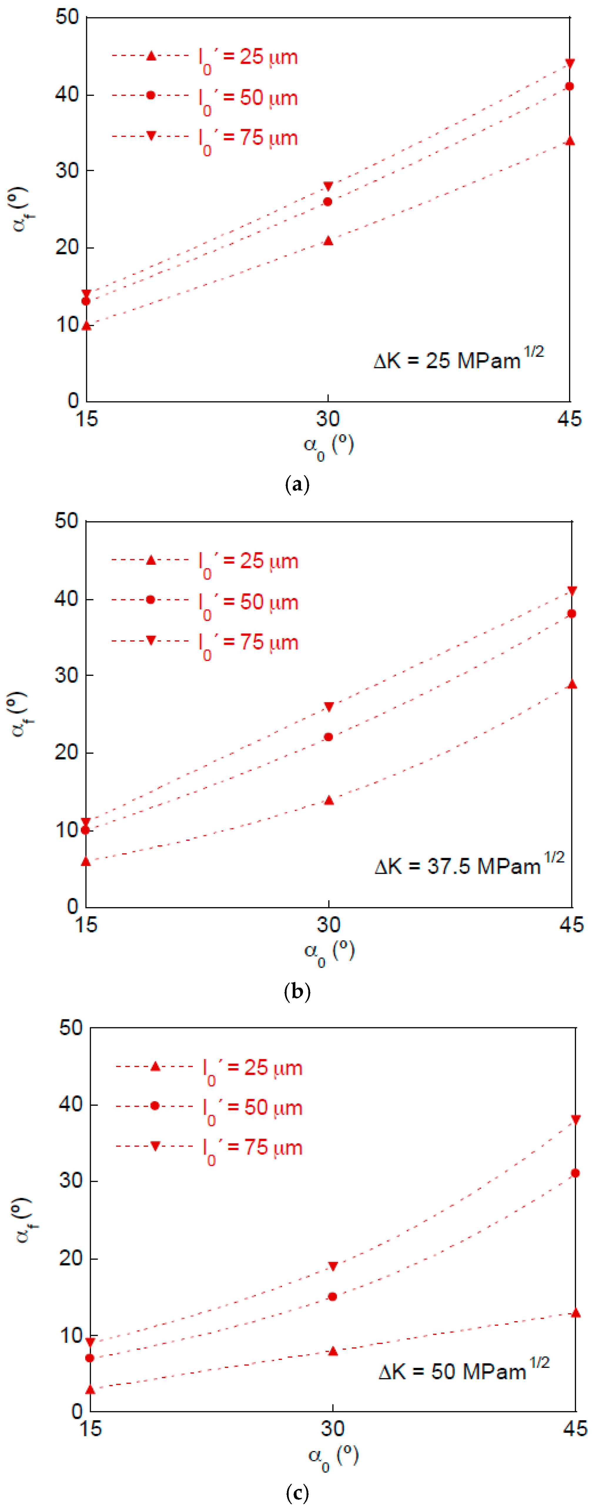
Cracks with a kinked tip in a plate subjected to remote mode I (opening) fatigue tensile loading exhibit a plastic crack advance tending towards a global mode I in spite of the initial locally-multiaxial mixed-mode.
(ii)
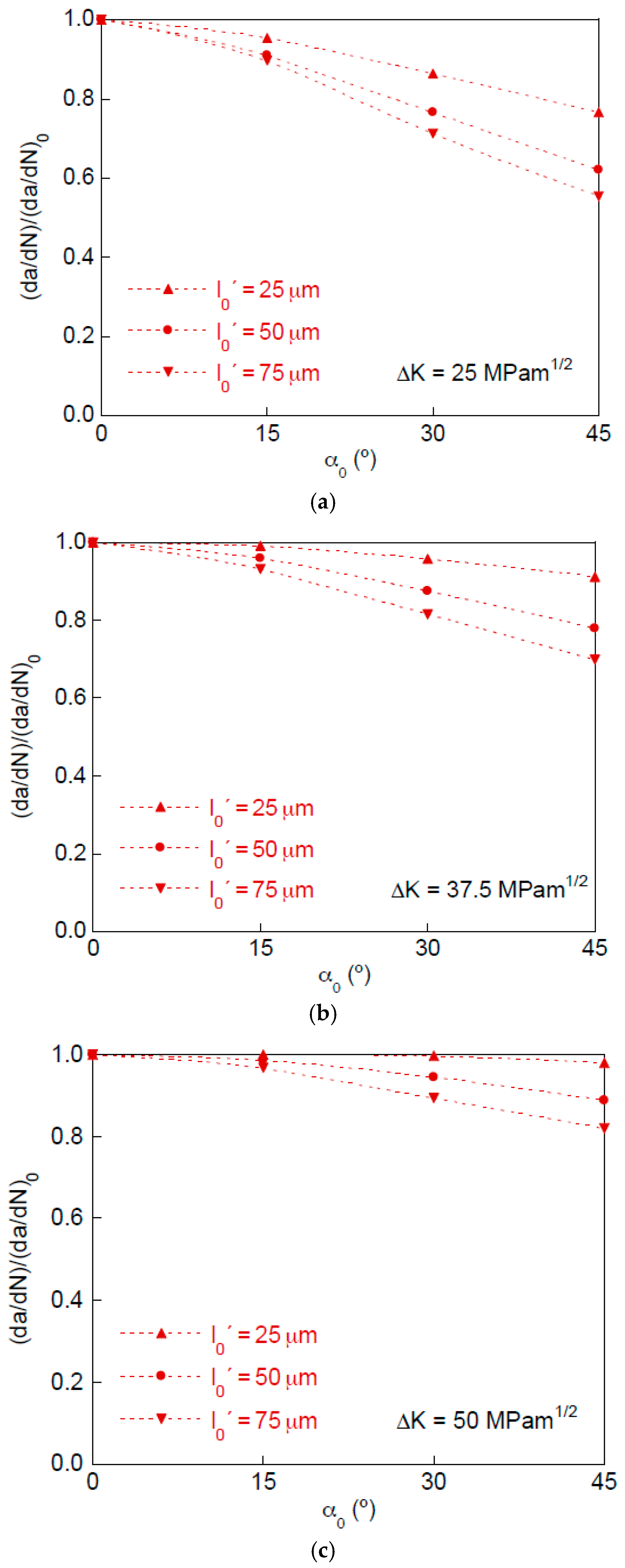
The deflection of the crack tip produced a retardation effect (that could be easily quantified through the retardation factor) on the fatigue crack growth, when compared to a fully straight crack.
(iii)
The retardation effect increased with the initial kinked crack tip angle and with the initial projected kinked crack tip length, while it decreased with the stress intensity factor range.
(iv)
A lower retardation effect could be associated with the decrease in the angle of propagated deflected crack tip, with respect to the initial deflected crack tip, and with an increase in the crack opening displacement (COD) in the deflected crack tip.

Author Contributions

Numerical modeling concept and design, J.T., J.-C.M., and B.G.; finite element modeling development, J.-C.M. and B.G.; data analysis, J.T., J.-C.M., and B.G.; writing and editing, J.T. All authors have read and agreed to the published version of the manuscript.

Funding

This research was funded by the following Spanish Institutions: Ministry for Science and Technology (MICYT; Grant MAT2002-01831), Ministry for Education and Science (MEC; Grant BIA2005-08965), Ministry for Science and Innovation (MICINN; Grant BIA2008-06810), Ministry for Economy and Competitiveness (MINECO; Grant BIA2011-27870), Junta de Castilla y León (JCyL; Grants SA067A05, SA111A07, SA039A08 and SA132G18), and Fundación Samuel Solórzano Barruso (Grant FS/9-2019) of the University of Salamanca (USAL).

Institutional Review Board Statement

Not applicable.

Informed Consent Statement

Not applicable.

Data Availability Statement

Not applicable.

Conflicts of Interest

The authors declare no conflict of interest. With regard to the research funds, the different institutions providing financial support for the scientific research had no role in the design of the study; in the collection, analyses, or interpretation of data; in the writing of the present manuscript; and in the decision to publish the results.

References

  1. Toribio, J.; Matos, J.C.; González, B. A macro- and micro-approach to the anisotropic fatigue behaviour of hot-rolled and cold-drawn pearlitic steel. Eng. Fract. Mech. 2014, 123, 70–76. [Google Scholar] [CrossRef]
  2. Kitagawa, H.; Yuuki, R.; Ohira, T. Crack-morphological aspects in fracture mechanics. Eng. Fract. Mech. 1975, 7, 515–529. [Google Scholar] [CrossRef]
  3. Suresh, S. Crack deflection: Implications for the growth of long and short fatigue cracks. Metall. Mater. Trans. A 1983, 14, 2375–2385. [Google Scholar] [CrossRef]
  4. Laird, C.; Smith, G.C. Crack propagation in high stress fatigue. Philos. Mag. 1962, 8, 847–857. [Google Scholar] [CrossRef]
  5. Toribio, J.; Kharin, V. Simulations of fatigue crack growth by blunting–re-sharpening: Plasticity induced crack closure vs. alternative controlling variables. Int. J. Fatigue 2013, 50, 72–82. [Google Scholar] [CrossRef]
  6. Toribio, J.; Kharin, V. Finite-deformation analysis of the crack-tip fields under cyclic loading. Int. J. Solids Struct. 2009, 46, 1937–1952. [Google Scholar] [CrossRef] [Green Version]
  7. Levkovitch, V.; Sievert, R.; Svendsen, B. Simulation of fatigue crack propagation in ductile metals by blunting and re-sharpening. Int. J. Fract. 2005, 136, 207–220. [Google Scholar] [CrossRef] [Green Version]
  8. Toribio, J.; Kharin, V. Large crack tip deformations and plastic crack advance during fatigue. Mater. Lett. 2007, 61, 964–967. [Google Scholar] [CrossRef]
  9. Tvergaard, V. Effect of underloads and overloads in fatigue crack growth by crack-tip blunting. Eng. Fract. Mech. 2006, 73, 869–879. [Google Scholar] [CrossRef]
  10. Hunnell, J.M.; Kujawski, D. Numerical simulation of fatigue crack growth behavior by crack-tip blunting. Eng. Fract. Mech. 2009, 76, 2056–2064. [Google Scholar] [CrossRef]
  11. Toribio, J.; Kharin, V.; Ayaso, F.J.; González, B.; Matos, J.C.; Vergara, D.; Lorenzo, M. Numerical and experimental analyses of the plasticity-induced fatigue crack growth in high-strength steels. Constr. Build. Mater. 2011, 25, 3935–3940. [Google Scholar] [CrossRef]
  12. McClung, R.C.; Thacker, B.H.; Roy, S. Finite element visualization of fatigue crack closure in plane stress and plane strain. Int. J. Fract. 1991, 50, 27–49. [Google Scholar]
  13. Tvergaard, V. On fatigue crack growth in ductile materials by crack–tip blunting. J. Mech. Phys. Solids 2004, 52, 2149–2166. [Google Scholar] [CrossRef]
  14. Toribio, J.; Kharin, V. Comments on simulations of fatigue crack propagation by blunting and re-sharpening: The mesh sensitivity. Int. J. Fract. 2006, 140, 285–292. [Google Scholar] [CrossRef]
  15. Tvergaard, V. Mesh sensitivity effects on fatigue crack growth by crack-tip blunting and re-sharpening. Int. J. Solids Struct. 2007, 44, 1891–1899. [Google Scholar] [CrossRef] [Green Version]
  16. Benedetti, M.; Fontanari, V.; Monelli, B.D.; Beghini, M. A fully parametric weight function for inclined edge cracks with a kink. Eng. Fract. Mech. 2015, 136, 195–212. [Google Scholar] [CrossRef]
  17. Li, Y.; Sun, T.; Gao, Q.; Tan, C. A stress intensity factor estimation method for kinked crack. Eng. Fract. Mech. 2018, 188, 202–216. [Google Scholar] [CrossRef]
  18. Carpinteri, A.; Spagnoli, A.; Vantadori, S.; Viappiani, D. Influence of the crack morphology on the fatigue crack growth rate: A continuously-kinked crack model based on fractals. Eng. Fract. Mech. 2008, 75, 579–589. [Google Scholar] [CrossRef]
  19. Suresh, S. Micromechanisms of fatigue crack growth retardation following overloads. Eng. Fract. Mech. 1983, 18, 577–593. [Google Scholar] [CrossRef] [Green Version]
  20. Handerhan, K.J.; Garrison Jr., W. M. A study of crack tip blunting and the influence of blunting behavior on the fracture toughness of ultra high strength steels. Acta Metall. Mater. 1992, 40, 1337–1355. [Google Scholar] [CrossRef]
  21. Castro, J.T.P.; Meggiolaro, M.A.; Miranda, A.C.O. Singular and non-singular approaches for predicting fatigue crack growth behaviour. Int. J. Fatigue 2005, 27, 1366–1388. [Google Scholar] [CrossRef]
  22. Rice, J.R.; Tracey, D.M. Computational Fracture Mechanics. In Numerical and Computer Methods in Structural Mechanics; Academic Press: New York, NY, USA, 1973; pp. 585–623. [Google Scholar]
  23. McMeeking, R.M. Finite deformation analysis of crack-tip opening in elastic-plastic materials and implications for fracture. J. Mech. Phys. Solids 1977, 25, 357–381. [Google Scholar] [CrossRef]
  24. Savruk, M.P. Stress Intensity Factors in Solids with Cracks; Naukova Dumka: Kiev, Ukraine, 1988. (In Russian) [Google Scholar]
  25. Suresh, S. Fatigue of Materials, 2nd ed.; Cambridge University Press: Cambridge, UK, 1994. [Google Scholar]
  26. Fleck, N.A. Finite element analysis of plasticity-induced crack closure under plane strain conditions. Eng. Fract. Mech. 1986, 25, 441–449. [Google Scholar] [CrossRef]
  27. Paris, P.C.; Erdogan, F. A critical analysis of crack propagation laws. J. Basic Eng. 1963, 85D, 528–534. [Google Scholar] [CrossRef]
  28. Toribio, J.; Matos, J.C.; González, B. Influence of crack micro-roughness on the plasticity-induced fatigue propagation in high strength steel. Frat. Integrità Strutt. 2017, 41, 62–65. [Google Scholar] [CrossRef] [Green Version]
Figure 1. Initial geometry: (a) general view and (b) kinked crack tip.
Metals 11 00541 g001
Figure 2. Finite element mesh: (a) general view and (b) kinked crack tip.
Metals 11 00541 g002
Figure 3. Crack growth vs. number of cycles: (a) ΔK = 25 MPam1/2 and (b) ΔK = 50 MPam1/2.
Metals 11 00541 g003
Figure 4. Initial and deformed crack tips after applying 20 cycles (with the cumulative equivalent plastic strain in color) for the totally straight crack: (a) b0 = 5 μm, ΔK = 50 MPam1/2; (b) b0 = 0.5 μm, ΔK = 50 MPam1/2; (c) b0 = 50 μm, ΔK = 25 MPam1/2; and (d) b0 = 50 μm, ΔK = 50 MPam1/2.
Metals 11 00541 g004
Figure 5. Plasticity-induced fatigue crack propagation curve in the Paris regime.
Metals 11 00541 g005
Figure 6. Retardation factor of the fatigue crack growth rate for the kinked crack tip: (a) ΔK = 25 MPam1/2; (b) ΔK = 37.5 MPam1/2; and (c) ΔK = 50 MPam1/2.
Metals 11 00541 g006
Figure 7. Initial and deformed crack tips after 20 cycles (with the cumulative equivalent plastic strain in color) for the kinked crack tip with ΔK = 25 MPam1/2.
Metals 11 00541 g007
Figure 8. Initial and deformed crack tips after 20 cycles (with the cumulative equivalent plastic strain in color) for the kinked crack tip with ΔK = 50 MPam1/2.
Metals 11 00541 g008
Figure 9. Final angle of the kinked crack tip after 20 cycles: (a) ΔK = 25 MPam1/2; (b) ΔK = 37.5 MPam1/2; and (c) ΔK = 50 MPam1/2.
Metals 11 00541 g009
Figure 10. Maximum crack opening displacement (COD) in the kinked crack tip after 20 loading cycles, as a function of the projected length l0’, for different ΔK (SIF range) levels.
Metals 11 00541 g010
Publisher’s Note: MDPI stays neutral with regard to jurisdictional claims in published maps and institutional affiliations.

