Article

The Influence of Magnetic Field on Fatigue and Mechanical Properties of a 35CrMo Steel

1
School of Mechanical Engineering, University of Science and Technology Beijing, Beijing 100083, China
2
School of Electrical, Computer and Telecommunications Engineering, University of Wollongong, Wollongong, NSW 2522, Australia
3
State Key Laboratory for Advanced Metals and Materials, University of Science and Technology Beijing, No. 30, Xueyuan Road, Beijing 100083, China
*
Author to whom correspondence should be addressed.
Metals 2021, 11(4), 542; https://doi.org/10.3390/met11040542
Submission received: 23 February 2021 / Revised: 19 March 2021 / Accepted: 22 March 2021 / Published: 26 March 2021

Abstract

:
The influence of a magnetic field of 1.2–1.3 T on the variation of the fatigue behaviors and the mechanical properties of a 35CrMo steel after fatigue tests are investigated in this paper, in order to provide a basic guidance on the application in the similar environment of electrical machinery or vehicles. The microstructures of samples tested with and without magnetic fields are observed and analyzed by XRD, SEM, and TEM techniques. The fatigue life cycles are slightly increased by about 10–15% under magnetic field of 1.2–1.3 T according to the experimental results. A small increment of yield strength under fatigue life cycles of 10,000, 50,000, and 100,000 times is caused by the magnetic field, although the enhancement is only of 5–8 MPa. The dislocation density of the specimen is increased and the uniformity of dislocations is improved by magnetic fields applied during fatigue tests under the same load and cycles. The formation of micro-defects or micro-cracks will be postponed by the improvement in homogeneity of the material, leading to the increase of mechanical properties. The strengthening mechanisms such as deformation hardening and dislocation hardening effects are enhanced by the dislocation entangled structures and the higher density caused by magnetic field.

1. Introduction

The magnetic field has been reported to show a prominent effect on the nucleation and growth rate of new phase [1,2,3] in metallic materials. Consequently, the magnetic field has been introduced into heat treatment or deformation process in order to control the microstructure and properties of the materials [4]. The iron-base alloys are considered as a typical material that can be affected by a magnetic field owing to the inter-reaction between magnetization and solid transformations.
The isothermal phase transformations of iron and steel can be accelerated introducing magnetic field due to the decrease of the Gibbs free energy associated with ferromagnetic product phase [5]. The amount of bainitic ferrite is reported to be increased by ~4.2% compared with the normal aus-tempering process, under a 1.5 T pulse magnetic field during the aus-tempering process of a bainitic steel [6]. The precipitation process is also promoted by magnetic field, resulting in the variation of types and distributions of these precipitations, especially carbides in steels [7].
The properties of ferromagnetic steels at room temperature can also be affected by magnetic field, especially the Young’s modulus due to magneto-elasticity [8] and plastic deformation due to magneto-plasticity [9]. There are three mechanisms relating to the effects of magnetic field on the mechanical properties of materials based on the previous works [10,11]: (1) the phase transformation [12], (2) precipitation kinetics [13], and (3) the interaction behaviors between microstructure/dislocations and magnetic domain walls [14].
There are several conflicting evidences reported on the influence of high magnetic fields on the mechanical properties of different metallic materials. It is confirmed that the fatigue cycle life of pure iron is reduced in a saturating magnetic field at room temperature [14], caused by the enhancement of dislocation mobility and strain ageing. However, no further microscopy examinations have been performed to support this assumption. It has also been reported that the modulus of elasticity and ductility of plain carbon steel is slightly reduced in a saturating magnetic field by affecting the volume percent of the ferrite phase [15]. In contrast, the proportionality limit of a Eurofer-97 (Fe-8.95Cr-0.11C-0.03Si-0.55Mn-0.013Ni-1.06W-0.202 V steel) steel is increased by ~2.6% (from 514 ± 4.5 MPa to 528 ± 10 MPa) with the addition of a transverse magnetic field of 1.5 T, while the ultimate tensile strength and elongation are increased by only less than <1% [16]. The Vickers hardness of steel of 1 wt% C containing Mn and/or Cr is increased by approximately 2–8% with a 50 T/m magnetic field gradient applied and the hardening value varied with the chemical compositions. [17]. It is found in [18] that the fatigue lifetime of a AISI 8620 steel is extended with the increase of yield strength, tensile strength, and elongation, and the reduction of elastic modulus at initial step (10 days of exposure time) during the tests under magnetic field.
The 35CrMo steel [19,20,21,22,23] is considered as an important material used in motor shafts, large gears, or screw bolts in engineering and car industries. Therefore, it is very essential to investigate the mechanical properties and fatigue behaviors of this material under magnetic fields since the similar environment shall be involved in electrical machinery or vehicles [24,25]. In this paper, the variation of fatigue behaviors and the mechanical properties after fatigue tests are conducted to investigate the influence of magnetic fields. The microstructures of samples tested with and without magnetic fields are observed and analyzed by XRD, SEM, and TEM techniques. The behaviors and mechanisms corresponding to the influence of magnetic fields on fatigue behaviors and the mechanical properties are discussed in this paper, in order to develop a further theoretical direction for the applications of this type of steel used in magnetic environment.

2. Materials and Methods

The commercial 35CrMo steel is used in the study, the chemical compositions of which are listed in Table 1. The specimens are normalized at 850 oC for 30 min, air cooled, and then tempered at 550 °C for 2 h. The mechanical properties of this steel is listed in Table 2, which are used for the comparison of the properties after fatigue experiments with and without magnetic field. Two groups of cylindrical specimens with dimension of Φ20 mm × 200 mm are cut from the steel bar used for tensile fatigue tests under 450 MPa and 500 MPa, the frequency of 80 Hz, and stress ratio r = −1. One group of the specimens is located in a magnetic field of about 1.2–1.3 T experiments of the other group are carried out without magnetic field. The tensile specimens with dimension of Φ10 mm × 100 mm are cut from the fatigue specimens under 450 MPa for different life cycles, in order to study the influence of magnetic field on the mechanical and fatigue behaviors, as shown in Figure 1. At least two same specimens are cut and machined, in order to reduce the experimental errors.
The specimens of fatigue and mechanical experiments are cut into cylinders with dimension of Φ5 mm × 10 mm, sanded and polished for microstructure observations. These specimens are etched in a mixed solution containing 8% HNO3 and 92% ethanol (C2H5OH) for 10–20 s to reveal the microstructure.
Observations of scanning electron microscope (SEM) are carried out using a Zeiss supra55 type SEM microscope. The samples are polished and cut into discs with diameters of 3 mm and thickness of 30–40 μm, and then prepared by double jet electropolishing technique using a TenuPol-5 type polisher. Transmission electron microscopy (TEM) observation is carried out using a Tecnal-G2-F20 transmission electron microscope at an operating voltage of 200 kV. The specimens corresponding to different fatigue life cycles with and without magnetic field are analyzed by X-ray diffraction (XRD) using a TTRIII multifunctional X-ray diffractometer with a scan angle range from 35° to 95°, and the scanning rate was 4°/min.

3. Results

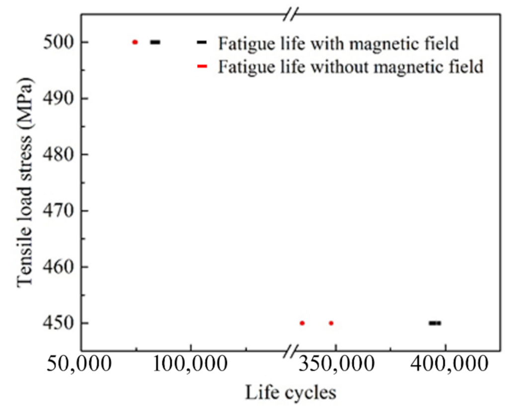
3.1. The Variation of Fatigue and Mechanical Behaviors with and without Magnetic Field

The fatigue life cycles of this 35CrMo steel is shown in Figure 2, under the loading stress of 450 MPa and 500 MPa, with and without the magnetic field. It is clearly shown that the fatigue life cycles are slightly increased by about 10–15% under the magnetic field of 1.2–1.3 T according to the experimental results. The fatigue life cycles are determined to be 390,000–398,000 times under tensile load of 450 MPa and 90,000–96,000 times under the load of 500 MPa with magnetic field, which are higher than those of 330,000–350,000 times under tensile load of 450 MPa and 85,000–89,000 times under the load of 500 MPa without magnetic field. These results show good agreement with some previous reports of other types of steel [16,17,23], which believe that the external magnetic field which causes some degree of domain rotation of dislocations necessarily leads to the decrease of the orientation randomness.
The tensile properties of 35CrMo steel after the fatigue tests for different life cycles are also influenced by magnetic field, although the increment of strength is small. The stress–strain curves obtained in the specimens cut from the fatigue samples (as shown in Figure 1) that have experienced different fatigue life cycles with and without magnetic field are shown in Figure 3a–c, suggesting that the strength of this material is increased by the magnetic field. The variation of yield strength of 35CrMo steel after the fatigue treatment for different life cycles tested with and without magnetic field are compared in Figure 3d. A small increment of yield strength under fatigue life cycles of 10,000, 50,000, and 100,000 times is caused by the magnetic field, with only the enhancement of 5–8 MPa of yield strength observed in Figure 3a–d. The numerical values on the longitudinal coordinates of Figure 3 are partially illustrated to show the small difference of stress and strength with and without magnetic field. It is similar to the previous reports [16,17,18] that the strength is enhanced by the magnetic field which can cause the pinning effect of magnetic domain wall on dislocations. This mechanism is discussed in the next section.

3.2. The Variation of Microstructures and X-ray Diffractions

The microstructures of 35CrMo steel that experienced fatigue tests of 450 MPa for 10,000 cycles with and without magnetic field are shown in Figure 4a,b. It can be seen that very similar microstructures containing typical tempering structures of ferrite and cementites corresponding to the two states are revealed, due to the fatigue tests at room temperature, i.e., below the critical temperatures of microstructure or phase transformation. However, there should be some differences in the finer structures especially the dislocation distributions since the mechanical properties are influenced by magnetic field, which is discussed in the next section by the TEM observations.
The similar results of X-ray diffractions (XRD) are shown in Figure 5, indicating that no apparent variation of microstructures are found in the specimens that experienced fatigue tests of 450 MPa for 10,000 cycles under magnetic field of 1.2–1.3 T (a) or no magnetic field (b), which is in good agreement with the SEM observations. However, the width of the diffraction peaks may be different although it is difficult to distinguish it by direct observation of Figure 5a,b. The half band width (I) of XRD patterns can be quantitatively estimated by the software JADE-5 and Origin. The XRD results are considered as an evidence on the variation of dislocation distributions influenced by magnetic field, as shown in Figure 5a,b, since the relationship between half band width of XRD patterns and dislocation densities have been investigated and proved in other works [26,27]. The width of diffraction peaks along (110) and (200) direction is found increased in the specimen that experienced fatigue tests of 450 MPa for 10,000 cycles under magnetic field of 1.2–1.3 T than the ones without magnetic field, by comparing the XRD results in Figure 5a,b. It has been widely accepted that the dislocation density in material can be related and estimated by the half band width of diffraction peaks along the crystal orientation of dislocation slip [26]. The relationship between dislocation density D and half band width I of diffraction peaks can be expressed as [28]:
D = I 2 2 ln 2 π b 2
where b is the Burke vector, which is considered as a constant for the same material. The half band width I can be estimated from the XRD results. The dislocation density D estimated by Equation (1) may not be very accurate due to the measurement errors of X ray diffraction patterns. However, it is feasible to believe that there is a proportional relationship between D and I2, according to Equation (1) and some other similar theories. The half band width I of the specimen that experienced fatigue tests of 450 MPa for 10,000 cycles under magnetic field is determined to be 0.5941–0.5988° and the one without magnetic field is 0.5771–0.5900°. Therefore, I2 can be estimated to be 0.3530–0.3586 and 0.3330–0.3481, revealing a decrease caused by the magnetic field. It is consequently suggested that the dislocation density of the specimen is increased by the magnetic field during the fatigue tests under the same load and cycles [29].

3.3. The Fracture Morphology of Tensile Specimens

Some differences of deformation behaviors can also be reflected by the fracture morphology of tensile specimens that experienced fatigue tests of 50,000 cycles under the load of 450 MPa with and without magnetic field, as shown in Figure 6. Similar fracture morphology containing a combination of dimples and inter-granular surfaces is revealed in Figure 6a. However, it can be seen that more amount of dissociated fracture surfaces are found in the fracture morphology of magnified photographs in Figure 6b, compared with that in Figure 6a. This difference can be attributed to the influence of magnetic field on the dislocation distributions. It is suggested by the dissociated fracture surfaces shown in Figure 6b that the ductility and plasticity of the material are reduced by fatigue tests due to the formation of micro-defects [21,23,29]. The material has intrinsic defects, such as, dislocation, void, and so on, where stress concentration is easy to occur and the stress intensity could be larger. More amount of dimples as shown in Figure 6a may suggest that more dislocations are formed and pinned by the magnetic domain walls, which are coherent with the XRD results.

4. Discussion

The increment of fatigue life cycles as well as the mechanical properties of 35CrMo steel that experienced fatigue tests are obtained by introducing the magnetic fields, although very small due to the stable phase and microstructure of this material at room temperature. It is suggested by the experimental results that the influence of magnetic fields on dislocation movement and distributions is considered as the leading reason, which is also in good agreement with the difference of dislocation density determined in Figure 5 and the fracture morphology in Figure 6.
The influence of magnetic field on dislocation distributions and precipitations has been discussed by several previous works [15,16,26,28,29]. The feature has been well accepted that crystal with magnetic anisotropic properties can become aligned to the magnetic field direction [11,13], which is considered as the theoretical basis on the influence of magnetic field on the phase transformation, fatigue, and mechanical properties. It is believed that the magnetization process can cause the movement of domain walls in the ferromagnetic materials. The presence of these walls, which has been confirmed by several previous works [26,27,28], can affect the plastic deformation by hindering the dislocation movement, similar to grain boundaries. Therefore, the application of an external magnetic field which causes some degree of domain rotation necessarily decreases their orientation randomness. In other words, the application of external magnetic field provides energy to the specimens. The dislocations can also pin magnetic domain walls, creating obstacles to the domain wall movement [18,19].
This dislocation distribution behaviors can be confirmed by TEM observation in Figure 7. It is clearly seen in Figure 7a that larger number of dislocations are found at the grain boundaries and inside the grains in the specimens that experienced fatigue tests under the magnetic field, compared with the photograph observed in the one without magnetic field as shown in Figure 7b. It can be seen that the distributions of dislocations is fairly uniform at the grain boundaries and inside the grains, compared with the fatigue behaviors without magnetic field which have been reported otherwise [21,22,23]. The influence of magnetic field on the distributions of dislocations has been confirmed by several studies [18,27,28] that the dislocations at the grain boundaries of the sample are dispersed and diffused from the grain boundaries to the inside of the grains with magnetic field due to the influence of magnetic domain walls. Meanwhile, the dislocation structure at the grain boundaries can spread widely and a large number of dislocations appear in the grains with higher magnetic field. Therefore, it is reasonable to believe this change in dislocation structure can lead to a more uniform distribution of residual stress. Therefore, the dislocation structure becomes more uniform, as shown by the comparison of Figure 7a,b, suggesting that the homogeneity of the material also improves. Then the formation of micro-defects or micro-cracks will be postponed by the improvement in homogeneity of the material, leading to the increase of fatigue life cycles of the steel. As for the mechanical properties of 35CrMo steel that experienced the fatigue tests, this uniformly distributed dislocations are also helpful to improve the strength. It is then suggested that deformation hardening and dislocation hardening effects shall be increased by the observation of many dislocation-entangled structures revealed in Figure 7 and the higher density determined based on the XRD results in Figure 5. Another estimation from the rather small value of increment of mechanical properties as mentioned in the previous section is that the influence of magnetic field is limited at room temperature, since the movement ability of dislocations is low and no phase transformation and precipitation occur.

5. Conclusions

In this study, the influence of magnetic fields of 1.2–1.3 T on the variation of fatigue behaviors and the mechanical properties after fatigue tests are investigated, in order to provide the basic guidance on the application of this type of steel in the similar environment of electrical machinery or vehicles.
The following conclusions can be drawn from this study:
(1)
The fatigue life cycles are slightly increased by about 10–15% under magnetic field of 1.2–1.3 T according to the experimental results. A small increment of yield strength under fatigue life cycles of 10,000, 50,000 and 100,000 times is caused by the magnetic field, with the enhancement of only 5–8 MPa.
(2)
The dislocation density of the specimen is increased and the uniformity of dislocations is improved by magnetic field during the fatigue tests under the same load and cycles. The formation of micro-defects or micro-cracks will be postponed by the improvement in homogeneity of the material, leading to the increase of mechanical properties.
(3)
The strengthening mechanisms such as deformation hardening and dislocation hardening effects were enhanced by the dislocation entangled structures and the higher density caused by magnetic field. Another estimation from the rather small value of increment of mechanical properties as mentioned in the previous section is that the influence of magnetic field is limited at room temperature, since the movement ability of dislocations is low and no phase transformation and precipitation occur.

Author Contributions

Conceptualization, Q.G. and X.H.; methodology, X.H.; formal analysis, J.X.; investigation, Q.G. and X.H.; writing—original draft preparation, Q.G.; writing—review and editing, X.H. and Z.G. All authors have read and agreed to the published version of the manuscript.

Funding

This work was supported by the National Key Research and Development Plan Project (2018YFC0604402) and the Fundamental Research Funds for the Central Universities (grant nos. FRF-IDRY-19-012), China.

Institutional Review Board Statement

The study was conducted according to the guidelines of the Declaration of Helsinki, and approved by the Institutional Review Board (or Ethics Committee) of NAME OF INSTITUTE (protocol code 1139136 and date of approval 23 March 2021).

Informed Consent Statement

Informed consent was obtained from all subjects involved in the study.

Data Availability Statement

Not applicable.

Acknowledgments

This work was supported by the National Key Research and Development Plan Project (2018YFC0604402) and the Fundamental Research Funds for the Central Universities (grant nos. FRF-IDRY-19-012), China.

Conflicts of Interest

The authors declare no conflict of interest.

References

  1. Molodov, D.A.; Konijnenberg, P.J. Grain boundary and grain structure control through application of a high magnetic field. Scripta Mater. 2006, 54, 977–981. [Google Scholar] [CrossRef]
  2. Song, J.Y.; Zhang, Y.D.; Zhao, X.; Zuo, L. Effects of high magnetic field strength and direction on pearlite formation in Fe-0.12%C steel. J. Mater. Sci. 2008, 43, 6105–6108. [Google Scholar] [CrossRef]
  3. Zhang, Y.; Esling, C. Phase Transformations in Steels: The Effect of a Magnetic Field on Phase Transformations in Steels; Woodhead publishing: Sawston, UK, 2012; pp. 555–580. [Google Scholar]
  4. Akhbarizadeh, A.; Amini, K.; Javadpour, S. Effect of simultaneous magnetic field and deep cryogenic heat treatment on the microstructure of 1.2080 tool steel. Mater. Des. 2012, 35, 484–490. [Google Scholar]
  5. Shimozono, T.; Kohno, Y.; Konishi, H.; Shibata, K.; Ohtsuka, H.; Wada, H. Effects of pre-strain, heat treatments and magnetic fields on α′ martensite formation in Fe- 25.5%Ni-3–5%Cr alloys. Mater. Sci. Eng. A 1999, 273–275, 337–341. [Google Scholar] [CrossRef]
  6. Nan, W.; Zhang, D.; Li, L.; Li, Q.; Zhai, Q. Effect of pulse magnetic field on isothermal bainitic transformation process in Cr5 steel. In Proceedings of the TMS 2016 145th Annual Meeting & Exhibition, Nashville, TN, USA, 14–18 February 2016; Springer International Publishing: Cham, Switzerland, 2016; pp. 619–624. [Google Scholar]
  7. Hou, T.; Wu, K. The influence of strong magnetic field on alloy carbide precipitation in Fe-C-Mo alloy. In Advanced Steels; Weng, Y., Dong, H., Gan, Y., Eds.; Springer: Berlin/Heidelberg, Germany, 2011; pp. 509–511. [Google Scholar]
  8. Cullity, B.D.; Graham, C.D. Introduction to Magnetic Materials; John Wiley & Sons: Hoboken, NJ, USA, 2011. [Google Scholar]
  9. Molotskii, M.I. Theoretical basis for electro-and magnetoplasticity. Mater. Sci. Eng. A 2000, 287, 248–258. [Google Scholar] [CrossRef]
  10. Klypin, A. Effect of magnetic and electric fields on creep. Met. Sci. Heat Treat. 1973, 15, 639–642. [Google Scholar] [CrossRef]
  11. Bida, G.V.; Nichipuruk, A.P.; Kamardin, V.M.; Stashkov, A.N. The Structure and the Magnetic and Mechanical Properties of Steel M74 and the Possibility of Nondestructive Testing of Heat-Treatment-Hardened Rails. Russ. J. Nondestruct. Test. 2005, 41, 391–402. [Google Scholar] [CrossRef]
  12. Zhang, Y.; Gey, N.; He, C.; Zhao, X.; Zuo, L.; Esling, C. High temperature tempering behaviors in a structural steel under high magnetic field. Acta Mater. 2004, 52, 3467–3474. [Google Scholar] [CrossRef]
  13. Hou, T.P.; Wu, K.M.; Liu, W.M.; Peet, M.J.; Hulme-Smith, C.N.; Guo, L.; Zhuang, L. Magnetism and high magnetic-field-induced stability of alloy carbides in Fe-based materials. Sci. Rep. 2018, 8, 3049. [Google Scholar] [CrossRef]
  14. Bose, M. Effect of saturated magnetic field on fatigue life of carbon steel. Phys. Status Solidi 1984, 86, 649–654. [Google Scholar] [CrossRef]
  15. Sidhom, A.A.; Sayed, S.A.; Naga, S.A. The influence of magnetic field on the mechanical properties & microstructure of plain carbon steel. Mater. Sci. Eng. A 2017, 682, 636–639. [Google Scholar]
  16. Wang, Y.Q.; Gorley, M.; Kabra, S.; Surrey, E. Influence of a 1.5 T magnetic field on the tensile properties of Eurofer-97 steel. Fusion. Eng. Des. 2019, 141, 68–72. [Google Scholar]
  17. Shimotomai, M. Influence of magnetic-field gradients on the pearlitic transformation in steels. Mater. Trans. 2003, 44, 2524–2528. [Google Scholar] [CrossRef]
  18. Choi, K.J.; Yoo, S.C.; Ham, J.; Kim, J.H.; Jeong, S.Y.; Choi, Y.S. Fatigue behavior of AISI 8620 steel exposed to magnetic field. J. Alloys Compd. 2018, 764, 73–79. [Google Scholar] [CrossRef]
  19. Plekhov, O.; Palin-Luc, T.; Saintier, N.; Uvarov, S.; Naimark, O. Fatigue crack initiation and growth in a 35CrMo4 steel investigated by infrared thermography. Fatigue Fract. Eng. Mater. Struct. 2010, 28, 169–178. [Google Scholar] [CrossRef] [Green Version]
  20. Zhang, J.W.; Lu, L.T.; Shiozawa, K.; Zhou, W.N.; Zhang, W.H. Effect of nitrocarburizing and post-oxidation on fatigue behavior of 35CrMo alloy steel in very high cycle fatigue regime. Int. J. Fatigue 2011, 33, 880–886. [Google Scholar] [CrossRef]
  21. Hu, Z.; Fan, J.; Wu, S.; Dai, H.; Liu, S. Characteristics of Metal Magnetic Memory Testing of 35CrMo Steel during Fatigue Loading. Metals 2018, 8, 119. [Google Scholar] [CrossRef] [Green Version]
  22. Zheng, X.T.; Wu, K.W.; Wang, W.; Yu, J.Y.; Xu, J.M.; Ma, L.W. Low cycle fatigue and ratcheting behavior of 35CrMo structural steel at elevated temperature. Nucl. Eng. Des. 2017, 314, 285–292. [Google Scholar] [CrossRef]
  23. Wu, C.; Zhao, Y.; Xu, X.; Yin, P.; Qiu, X. Electropulse-induced laminated structures in a ferritic-pearlitic 35CrMo steel. Scr. Mater. 2019, 165, 6–9. [Google Scholar] [CrossRef]
  24. Liu, B.; He, G.; Jiang, X.; Zhu, M. Multi-axial fretting fatigue behaviour of 35CrMoA steel. Fatigue Fract. Eng. Mater. Struct. 2011, 34, 974–981. [Google Scholar] [CrossRef]
  25. Xiao, Z.B.; Huang, Y.C.; Liu, Y. Plastic Deformation Behavior and Processing Maps of 35CrMo Steel. J. Mater. Eng. Perform. 2016, 25, 1219–1227. [Google Scholar] [CrossRef]
  26. Wang, F.; Qian, D.; Hua, L.; Mao, H. Effect of high magnetic field on the microstructure evolution and mechanical properties of M50 bearing steel during tempering. Mater. Sci. Eng. A 2019, 771. [Google Scholar] [CrossRef]
  27. Shao, Q.; Wang, G.; Wang, H.; Xing, Z.; Fang, C.; Cao, Q. Improvement in uniformity of alloy steel by pulsed magnetic field treatment. Mater. Sci. Eng. A 2020, 799, 140–143. [Google Scholar] [CrossRef]
  28. Badano, G.; Robin, I.C.; Amstatt, B.; Gemain, F.; Baudry, X. Reduction of the dislocation density in molecular beam epitaxial CdTe(2 1 1)B on Ge(2 1 1). J. Cryst. Growth 2010, 312, 1721–1725. [Google Scholar] [CrossRef]
  29. Stepanov, G.V.; Kharchenko, V.V.; Kotlyarenko, A.A.; Babutskii, A.I. Effect of Pulsed Magnetic Field Treatment on the Fracture Resistance of a Cracked Specimen. Strength Mater. 2013, 45, 154–162. [Google Scholar] [CrossRef]
Figure 1. The illustration of fatigue tests containing magnetic field and the corresponding samples.
Metals 11 00542 g001
Figure 2. The fatigue life cycle under the load of 450 MPa and 500 MPa, with and without magnetic field.
Metals 11 00542 g002
Figure 3. The stress–strain curves of specimens after fatigue life of 10,000 cycles (a), 50,000 cycles (b), 100,000 cycles (c), and yield strength conducted by different fatigue tests life cycles (d) under the load of 450 MPa.
Metals 11 00542 g003aMetals 11 00542 g003b
Figure 4. The SEM photographs of the specimen that experienced fatigue tests of 450 MPa for 10,000 cycles under magnetic field of 1.2–1.3 T (a) and no magnetic field (b).
Metals 11 00542 g004
Figure 5. The X-ray diffraction patterns of the specimen that experienced fatigue tests of 450 MPa for 10,000 cycles under magnetic field of 1.2–1.3 T (a) or no magnetic field (b).
Metals 11 00542 g005
Figure 6. The SEM photographs of fracture morphology of tensile specimens that experienced fatigue tests of 50,000 cycles under the load of 450 MPa, (a) with magnetic field and (b) without magnetic field.
Metals 11 00542 g006
Figure 7. The TEM photographs of the specimen that experienced fatigue tests of 450 MPa for 10,000 cycles under magnetic field (a) and no magnetic field (b) of 1.2–1.3 T, revealing obvious dislocation tangles.
Metals 11 00542 g007
Table 1. The chemical compositions of 35CrMo steel in this study.
ElementsCCrMoSiMnNiSP
Contents0.360.900.210.250.500.10.020.02
Table 2. The mechanical properties of 35CrMo steel.
Tensile Strength (MPa)Yield Strength (MPa)Elongation (100%)Reduction of Area (100%)Hardness HBS
98383511.847230
Publisher’s Note: MDPI stays neutral with regard to jurisdictional claims in published maps and institutional affiliations.

