Article

Friction Stir Welding of AA2099-T83 and AA2060-T8E30 Aluminium Alloys with New Cr-Free Surface Treatments and Sealant Application

1
LORTEK Technological Centre, Basque Research and Technology Alliance (BRTA), 20240 Ordizia, Spain
2
Faculty of Engineering (MU-ENG), Mondragon Unibertsitatea, 20500 Arrasate-Mondragon, Spain
3
Hellenic Aerospace Industry S.A., 32009 Schimatari, Greece
*
Author to whom correspondence should be addressed.
Metals 2021, 11(4), 644; https://doi.org/10.3390/met11040644
Submission received: 25 February 2021 / Revised: 31 March 2021 / Accepted: 8 April 2021 / Published: 15 April 2021
(This article belongs to the Special Issue Dissimilar Material Welding and Joining)

Abstract

:
The feasibility for friction stir welding (FSW) surface-treated AA2099-T83 aluminium extrusions with AA2060-T8E30 aluminium sheets in the overlap configuration and using a sealant at the interface was investigated in this work. New Cr-free surface treatments such as thin film sulphuric acid anodising (TFSAA) and sol–gel were applied to the parent materials, and a sealant was applied before applying the FSW process. FSW welds were produced using several combinations of surface treatments and sealant application with no significant influence on FSW process stability and performance. The metallographic examination of the welds showed that a good protection of the crevice was achieved with some sealant accumulation at the edges of the overlapping region. The microstructural analysis showed no sealant remnants but the presence of some oxide remnants in the stir zone (SZ) of the welds, especially in the TFSAA treated parent material cases. However, these remnants did not show any significant effect in the static pull-out strength of the joints and failures at the most stressed zone of the AA2099-T83 extrusions outside the FSW weld region were consistently obtained.

Graphical Abstract

1. Introduction

The transportation industry in general and the aerospace industry in particular are continuously demanding lightweight load-bearing structures in order to achieve improvements in fuel consumption efficiency and reduction of CO2 emissions [1,2]. Although riveting is the dominant joining technology for manufacturing aircraft structures, other modern technologies such as friction stir welding (FSW) have been proposed as alternatives due to important benefits over riveting [3,4,5,6,7,8]. Weight saving and reduced manufacturing costs and times have been listed as some of the main advantages shown by FSW applied to the manufacturing of efficient aircraft structures [9,10]. This innovative manufacturing technology required the execution of lap joints by FSW, among other joint configurations and design possibilities [4]. Thus, the need to produce lap joints by FSW promoted the interest and investigations of this type of joint configuration by several authors [11,12,13,14,15,16,17,18]. These studies showed the importance of using an appropriate FSW tool design and welding parameters in order to achieve high-quality welds using different types of aluminium alloys.
High-strength aluminium alloys are key engineering materials widely considered for the manufacturing of efficient aircraft structures due to their low density and potential to produce light, strong structures [19]. The continuous search for low density and high strength in modern aluminium alloys promoted the maturation of the third generation of Al-Li alloy family. After many years of intense research and development efforts, numerous Al-Li alloys have been produced in several product forms, showing improved properties in comparison to the traditional 2XXX and 7XXX aluminium alloys such as higher modulus and higher specific strength [20]. Thus, the commercial availability of aluminium products with alloys such as AA2060 and AA2099 opens new opportunities to design efficient aeronautical and space structures. The possibility for producing joints by FSW using these alloys was investigated by some authors showing their potential for manufacturing stiffened panels by joining AA2099-T83 stringers to AA2060-T8E30 skin [18,21]. Other authors also showed the possibility of using other Al-Li alloys to produce FSW joints [22,23].
Another important issue to be considered for the design and manufacturing of aircraft structures is the corrosion resistance. In order to achieve a long-term operational capability, a variety of corrosion protection methods such as surface treatments and sealants are used in the aerospace industry. Operational considerations, societal concerns, as well as registration, evaluation, authorization and restriction of chemicals (REACH) regulations are creating a growing demand for the development of new effective and environmentally friendly technologies [24,25]. In addition to that, there is a continuous need to reduce the environmental footprint of the manufacturing technologies, as established in the advisory council for aviation research and innovation (ACARE) targets [26]. Thus, materials used in manufacturing airframe components need to become more resistant in corrosion and more eco-compliant in order to achieve an eco-friendly life cycle. This includes a significant decrease of hazardous materials during the manufacturing phase. In this context, chrome-free surface treatments such as thin film sulphuric acid anodising (TFSAA) and out-of-bath Sol–Gel sprayable application are being developed aiming at the replacement of current chromate anticorrosive protection processes [27].
From a general manufacturing of aircraft structures point of view, it is necessary to investigate the feasibility to combine surface treatments, sealants, and joining technologies. Several authors investigated the feasibility of FSW and its derivatives such as refill friction stir welding (RFSSW) for joining surface-treated aluminium alloys in the overlap configuration using sealants [28,29,30,31,32]. These studies demonstrated a good potential of FSW technologies to weld surface-treated aluminium alloys using sealants with appropriate welding conditions and materials. However, these studies focused mostly on conventional high-strength aluminium alloys of 2XXX and 7XXX series, as well as in standard chrome-based surface treatments such as Alodine-1200S Aero Chromate Chemical Film. The effects produced when combining FSW, Al-Li alloys, and innovative chrome-free surface treatments have not been investigated before in spite of being highly interesting. Thus, the present work focused on investigating the properties of FSW joints produced using surface-treated Al-Li alloys with sealant application and comparing their properties with FSW joints produced using non-treated alloys.

2. Materials and Methods

2.1. Base Materials and Surface Treatments

Lap joints were produced using Z-shaped extrusions of AA2099-T83 aluminium alloy on top of rolled sheets of AA2060-T8E30 aluminium alloy. The thickness of the AA2099-T83 extrusions was 2 mm, while the thickness of the AA2060-T8E30 sheets was 2.5 mm. The nominal chemical compositions of these aluminium alloys are shown in Table 1. First, 500 mm long extrusions were placed on top of sheets measuring 100 mm × 600 mm for the manufacturing of the welded coupons. Welded coupons composed by several combinations of surface treatments as well as sealant application at the matching interface between overlapping base materials were produced by FSW and examined. Thus, six different coupons were produced using two different types of surface treatments and the application of a sealant, as shown in Table 2.
Coatings of the AA2099-T83 aluminium extrusions and the AA2060-T8E30 sheets were produced by the Hellenic Aerospace Industry (HAI) using two different surface treatment techniques: (i) thin film sulphuric acid anodising (TFSAA) and (ii) sprayable application of sol–gel treatment (AC131 from 3M™). Both treatments are fully chromium free and REACH compliant. Prior to both (i) and (ii) treatments, the aluminium surfaces were given the following surface preparation: alkaline degreasing, rinsing, alkaline etching, rinsing, desmutting, and final rinsing.
TFSAA was initially performed in an experimental, lab-scale setup and then scaled-up in semi-industrial and final industrial conditions. During the anodising cycle the current density, and the electrolyte temperature were recorded. The experimental setup for TFSAA and the process parameters are given in Figure 1.
The sol–gel treatment by AC131 was applied with a spray-gun in order to reduce the needs of waste management. The treatment was performed respecting the pot life of the AC131 sol–gel solution, which is limited to few days.
The sealant selected for this investigation was Naftoseal® MC-780-class C (Chemetall GmbH, Frankfurt am Main, Germany), which is a two-component, manganese-dioxide cured polysulfide polymer system with reduced density typically used for fuel tank and fuselage seals in aerostructure manufacturing. The application of the sealant in the extrusion–sheet interface was performed in the uncured state right after mixing the two components and prior to the execution of the FSW process. A constant thickness of 0.2 mm of sealant was applied using an adhesive tape of the same thickness, removing the sealant remnants and the tape itself prior to the FSW process.

2.2. Friction Stir Welding Procedure

The AA2099-T83 extrusions and AA2060-T8E30 sheets were friction stir welded at LORTEK in the overlap configuration in an I-STIR PDS 4 machine operated in force control. The welding tool, which in previous investigations was shown to have an optimised design for the manufacturing of lap joints [17,21], consisted of a probe with 3 flats and a mixed thread with a diameter of 4 mm and a length of 2.5 mm. The shoulder had a flat shoulder of 10 mm in diameter. A specifically designed fixture and clamping system was used for the positioning of the AA2099-T83 extrusions on top of the AA2060-T8E30 sheets. All welds were performed at a clockwise rotational speed of 1200 rpm, a welding speed of 250 mm/min, and a forge force of 6.25 kN. The advancing side of the welds was oriented toward the vertical section of the extrusions and the retreating side toward the free side of the extrusions. The tilt angle of the tool was 1.5° in all cases. The main process parameters such as the torque, forge force, and penetration by the welding tool were recorded for their analysis during the FSW process using the controller of the FSW machine. The setup for the FSW process showing the specific fixture, welding tool, and the materials mounted on the FSW machine table as well as some completed FSW coupons can be observed in Figure 2.

2.3. FSW Weld Property Characterisation

The properties of the FSW welds were assessed by metallographic characterisation and static mechanical strength tests (pull-out tests). Cross-sectional specimens were cut perpendicular to the welding direction from each of the welded coupons. The specimens were prepared using standard procedures for mounting, grinding, and polishing to a mirror-like surface finish using a colloidal silica suspension. After this preparation, the specimens were etched using a diluted Keller’s reagent to reveal the microstructure. The initial metallographic examination of the cross-sectional specimens was performed by optical microscopy using an Olympus GX51 light optical microscope, before and after the chemical etching of the specimens in order to allow a more clear observation of the influences of the coatings in the welded region. The specimens were also characterised making use of both a Fei Nova NanoSEM 450 scanning electron microscope (SEM) and an Oxford Instruments X-Max 50 energy-dispersive X-ray spectroscopy (EDS) system.
The influence of the coatings and sealant in the static strength of the FSW joints was investigated by pull-out tests using a Zwick Roell Z100 tensile testing machine with a load capacity of 100 kN and a constant testing speed of 1.6 mm/min. Thirty mm wide test samples were cut from the welded coupons using electrical discharge machining (EDM). In these tests, the AA2060-T8E30 was clamped in a special fixture designed for the tests, and a pull-out force perpendicular to the weld surface was applied to the AA2099-T83 extrusion until fracture. Three samples from each FSW coupon, C1–C6, were tested, and average values of the maximum pull-out force were calculated.

3. Results

3.1. Reaction Forces and Tool Penetration during FSW

The torque, forge force, and penetration feedback signals were analysed in order to study the effects of the coatings and sealant on the FSW process stability. The representation of these signals as a function of time during the FSW process for coupon C1 can be observed in Figure 3, which is representative also for the rest of the coupons, C2–C6. The penetration of the tool during the plunging phase was carried out in position control at a constant speed of 5 mm/min until a penetration value of 2.5 mm. An initial peak of forge force, as indicated in detail A, was observed at the beginning of the plunging phase followed by a reduction, as shown in detail B, when the material below the probe of the tool was heated and softened. At the end of the plunging phase, a large increase of the forge force was observed when the tool shoulder contacted the material, as shown in detail C. As expected, a similar evolution of the torque was observed at this point where the contact of the shoulder with the material produced an increase in its value. Detail D indicates how the forge force decreased again during the dwell time of 1 s applied for the homogenisation of the heat in the shoulder contact region before starting the tool travelling phase.
The evolution of the forge force and torque during the tool travelling phase are indicated by detail E1 in Figure 3, whereas the evolution of the penetration is indicated by detail E2. This travelling phase was performed in force control so that the commanded value of the forge force was maintained at 6.25 kN. Slight variations of the tool penetration can be observed, which are produced by the FSW machine in order to maintain the commanded forge force value. The relatively constant values observed for penetration and torque during the tool travelling phase were indicative of a stable FSW process. Note that these two values are not commanded in the force control mode employed in these FSW welds.
Average values of torque and tool penetration during the travelling phase in the period comprehended between 40 and 140 s were calculated for all welded coupons. The representation of these values is shown in Figure 4. Similar values with no significant variations were observed for the torque and the tool penetration in all coupons. A maximum variation of 8% between the maximum and minimum torque average values calculated for the C1-C6 coupons was determined. Regarding the penetration, the maximum variation was 4%. These variations are indicative that the FSW process was stable and not significantly influenced by the surface conditions nor the sealant application before FSW.

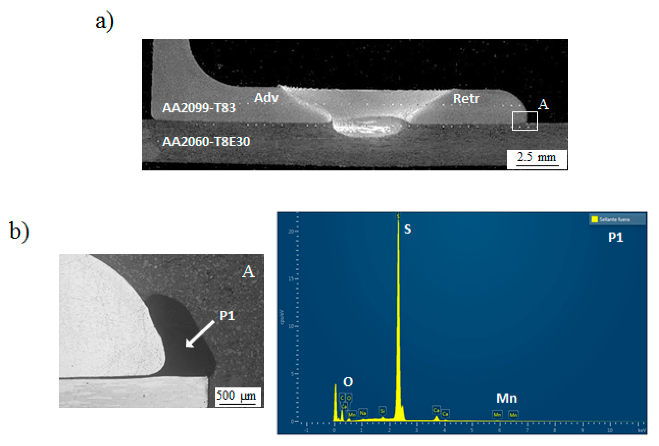
3.2. Metallographic Characterisation

A metallographic characterisation was performed in order to investigate the effects of the coatings and sealant on the microstructure of the welds. Cross-sectional macrographs of the weld specimens obtained from C1–C6 coupons are shown in Figure 5. No significant differences nor measurable volumetric defects were observed in the macrographs, showing similar macrostructural characteristics and shapes for all examined welds. All welds showed good soundness with all the typical FSW microstructural weld zones such as the stirred zone (SZ), thermo-mechanically affected zone (TMAZ), heat-affected zone (HAZ), and parent metal (PM). A small hook imperfection, which is a typical feature found in FSW lap joints [33], was consistently observed and similar in size in all welds at the AA2099-T83 extrusion and AA2060-T8E30 sheet interface in both advancing and retreating sides. These macrostructural characteristics are similar to the characteristics reported previously for similar welds by the authors [21].
Figure 6 shows a cross-sectional macrograph of the weld specimen obtained from coupon C4 and higher magnification (5×) micrographs of the crevice region in the AA2099-T83 extrusion and AA2060-T8E30 sheet interface. An accumulation of the Naftoseal® MC-780-Class C sealant in the crevice region can be clearly observed in details A and B, i.e., at the edges of the matching interfaces between the overlapping parent materials, indicating that a good protection of this crevice region was obtained by the sealant. These sealant accumulations were consistently observed also in the other coupons C5 and C6 that were produced using the sealant in the extrusion–sheet interface. It is worth noting that no macrostructural defects are observed in these welds using sealant at the matching interface. Thus, the achievement of a good protection of the crevice at the extrusion–sheet interface without impairing the weld quality seems to be feasible by combining un-cured sealant application and FSW.
Further microstructural details of the FSW welds were investigated using SEM observation complemented with EDS chemical analysis. Figure 7 shows the results obtained for such analysis performed with the FSW weld from coupon C1, which was produced with as-received base materials and without sealant application. The macrograph and the detail shown in Figure 7a were performed after chemical etching and before chemical etching respectively in order to get a more clear observation of the weld features. It can be observed that a very clear SZ region was obtained with no major contaminant agents, except in a reduced cold lap region located in the hook region of the retreating side (highlighted in detail A in Figure 7a). SEM observation and EDS analysis shown in Figure 7b revealed the presence of oxide remnants at the interface between the AA2099-T83 extrusion and the AA2060-T8E30 sheet, which are indicative of a non-complete break, dispersion, and mixing of the inherent oxide layer present at the surface of the parent materials before the FSW process.
Figure 8 shows the cross-sectional macrograph of coupon C2, as well as the SEM observation and the EDS analysis carried out at the interface between the AA2099-T83 extrusion and the AA2060-T8E30 sheet, as indicated by detail A in Figure 8a. The SEM analysis (Figure 8b) revealed the presence of continuous thin layers of aluminium oxide at the surface of both AA2099-T83 and AA2060-T8E30 alloys as a result of the TFSAA process applied to the parent materials before the FSW process. The thickness of the oxide layer in the AA2099-T83 extrusion was approximately 3 µm, whereas in the AA2060-T8E30 sheet, it was approximately 1 µm. The chemical composition analysis carried out by EDS in both oxide layers, which are represented as points P1 and P2 in Figure 8b, revealed an identical composition for both coatings, which was mainly composed of aluminium, oxygen, and sulphur. The sulphur content of the coating was indicative of the characteristics of the anodising process based on the use of sulphuric acid.
The microstructural analysis of the weld in coupon C2, which is shown in Figure 9, revealed an important presence of fragment remnants in the SZ. These fragment remnants can be observed as black particles in Figure 9b, and their dimension was estimated between 3 and 7 microns. It was found that the SZ region located in the advancing side was free from these fragment remnants, while the retreating side was more populated. At the centre of the SZ, the fragment remnants were relatively small and dispersed into the aluminium matrix, while closer to the edge of the retreating side, a continuous, thin layer formed by the remnants was observed. The EDS analysis of the fragment remnants showed a similar composition to the thin aluminium oxide layers identified at the surfaces of the parent materials (Figure 8) with the presence of some sulphur content. Therefore, it can be concluded that the presence of these fragment remnants is related to the incomplete break, dispersion, and mixing of the thin aluminium oxide coatings, which are originally at the surface of the TFSAA anodised parent materials before the FSW process. The morphology, size, and distribution of the fragment remnants is a consequence of the plasticised metal flow promoted by the tool during the FSW process.
Figure 10 shows a macrograph of the weld from coupon C6 and the detailed analysis of the crevice region between both parent materials. Similarly to the results shown in Figure 6, an accumulation of sealant at the crevice region was observed in the detail A from Figure 10a, which is magnified in the image of Figure 10b. The EDS analysis of the sealant corresponding to point P1 in Figure 10b revealed a high sulphur content with lower contents of other elements such as oxygen and manganese. This result is consistent with the composition of the sealant, which is a manganese-dioxide cured polysulphide polymer system. Thus, in the same way as the sulphur content was used for the tracing and identification of aluminium oxide fragment remnants coming from the coatings produced in the TFSAA treatments, the sulphur of the sealant was used for tracing the sealant remnants that could be present at C4, C5, and C6 welds. It is important to mention that the sulphur content in the sealant is significantly higher than in the aluminium oxide fragment remnants. This fact, along with the shape of the analysed remnants, made it possible to identify clearly their origin and nature.
Figure 11 shows the microstructural analysis carried out in the cross-section of the FSW weld obtained from coupon C6. The detail image obtained from the specimen before etching that can be observed in Figure 11a revealed a clear SZ region at the advancing side of the weld, while traces of remnants were present towards the retreating side. One could expect that these remnants had been formed as a result of a non-complete break, dispersion, and mixing of the Sol–Gel coating, sealant, and the inherent oxides that were present at the surface of the parent materials before the FSW process. Figure 11b presents the EDS analysis of the region indicated as detail A in Figure 11a. The compositional analysis of the remnants revealed contents of aluminium and copper, which are the main alloying elements of the parent metals, as well as oxygen very likely from the inherent oxide layer of the surface of the parent metals. Traces of sulphur that could indicate the presence of sealant remnants were not observed in any of the welds produced combining sealant application and FSW, i.e., coupons C4, C5, and C6. Thus, it seems that the sealant was displaced from the weld region towards the edges during the FSW process due to the pressure applied by the tool.

3.3. Pull-Out Strength

Quasi-static pull-out tests were performed in order to evaluate the influence of the coatings and sealant application in the strength of FSW welds. In these tests, the AA2060-T8E30 sheet was clamped, and a pulling force perpendicular to the weld surface was applied to the AA2099-T83 extrusion until the failure of the specimens, as shown in Figure 12. The maximum pull-out force for all specimens obtained from each FSW coupon C1–C6 as well as some examples of the failure mode observed for all specimens are presented in Figure 13. Very consistent maximum pull-out values of approximately 4.4 kN were obtained, except for the FSW specimens corresponding to coupon C3 that showed values of approximately 3.6 kN. This represents a reduction of 18% in the strength of the joints performed with Sol–Gel treated parent materials. This reduction was related to the larger distance of the weld with respect to the vertical part of the AA2099-T83 extrusion (indicated as “d” in Figure 12a), which generated a higher bending moment (M in Figure 12b) and stress concentration resulting in the failure of the stringer. This bending effect was reported by Mota de Siqueira et al. during pull-out tests carried out with similar overlap joint configurations [34]. For all the specimens tested in this study, the failure occurred consistently in the most stressed zone (region “e” in Figure 12b) at the AA2099-T83 extrusion outside the FSW weld region, as represented in Figure 12c. Figure 13b shows some examples of such failures.
Although a lower strength could be expected especially for FSW specimens obtained from coupons C2 and C5 due to the fragment remnants present in the retreating side of the SZ, they showed similar strength to the other specimens except for the mentioned C3 case.
Therefore, the failure was never located at any region of the FSW welds (SZ, TMAZ or _HAZ). All FSW welds showed higher strength than the most stressed zone located in the AA2099-T83 extrusions due to the bending effects and stress concentrations produced during the pull-out loading tests.

4. Conclusions

The influence of TFSAA and Sol–Gel surface treatments as well as the application of sealant before FSW was investigated in lap joints produced using AA2099-T83 aluminium Z-shaped extrusions on top of AA2060-T8E30 aluminium sheets. Based on the obtained results, the following conclusions were obtained:
  • No significant differences were observed in the force controlled FSW process after comparing the resulting torque and tool penetration during welding of non-treated, TFSAA treated, and Sol–Gel treated aluminium components (coupons C1, C2, and C3). The FSW process is similar and stable for all these conditions.
  • No significant differences were observed in the FSW process after comparing welding with and without sealant application at the interface of aluminium extrusions and sheets (C1, C2, C3 vs. C4, C5, and C6). The FSW process is similar and stable for all investigated surface treatments and sealant application conditions. The consistent accumulation of sealant observed at the stringer–skin crevice region at the edge of the matching interface between overlapping parent materials could provide good protection against corrosion for this type of joints and structures.
  • All investigated welds (C1–C6) presented similar macrostructural characteristics, such as a small hook imperfection, and no measurable volumetric defects were observed in any of them. However, the use of surface-treated parent materials, especially those with the TFSAA treatment, showed aluminium oxide fragment remnants at the retreating region of the SZ in the welds.
  • No sealant remnants were observed in any of the welds of the investigated FSW coupons. The sealant seems to be displaced from the weld region towards the edges by the pressure applied by the tool during the FSW process.
  • Consistent failures at the stringer (AA2099-T83 extrusion) outside the weld region and comparable failure loads were observed in pull-out static tests for all FSW specimens due to the bending effect and stress concentration at this point. Therefore, all tested FSW welds showed higher strength than the most stressed point of the joints despite the presence of the aluminium oxide remnants observed in some cases (C2 and C5).
According to the obtained results, FSW of TFSAA or Sol–Gel-treated third generation Al-Cu-Li aluminium alloys combined with sealant application at the crevice of the lap joints seems a feasible and promising technique for the manufacturing of lightweight aeronautic structures with good corrosion resistance. FSW could be applied directly on the surface-treated sheets and extrusions without the need for any pre-processing step to eliminate the coatings.

Author Contributions

Conceptualisation, E.A. and A.K.; formal analysis, E.A.; investigation, E.A., J.V., A.K. and I.H.; methodology, E.A. and A.K.; supervision, P.Á. and I.H.; writing—original draft, E.A. and A.K.; writing—review and editing, E.A., P.Á., I.H. and J.V. All authors have read and agreed to the published version of the manuscript.

Funding

This work has been performed in the frame of the project ecoTECH within the AIRFRAME ITD of the Clean Sky 2 programme of the H2020. The authors acknowledge the funding received for this project under the project ID 807083 of the call H2020-IBA-CS2-GAMS-2017.

Data Availability Statement

The data presented in this study are available on request from the corresponding author.

Acknowledgments

The authors would like to acknowledge Manuel De La Torre from BASF and Chemetall for providing the necessary Naftoseal® MC-780-class C sealant to perform the tests reported in the present work.

Conflicts of Interest

The authors declare no conflict of interest.

References

  1. Rendings, K.H. Aluminium structures used in aerospace—Status and prospects. Mater. Sci. Forum 2001, 242, 11–24. [Google Scholar] [CrossRef]
  2. Starke, E.A.; Staley, J.T. Application of modern aluminum alloys to aircraft. Prog. Aerosp. Sci. 1996, 32, 131–172. [Google Scholar] [CrossRef]
  3. Mendez, P.; Eagar, T. New trends in welding in the aeronautic industry. In Proceedings of the 2nd Conference of New Manufacturing Trends, Bilbao, Spain, 19–20 November 2002. [Google Scholar]
  4. Tavares, S.M. Design and Advanced Manufacturing of Aircraft Structures Using Friction Stir Welding. Ph.D. Thesis, Universidade do Porto, Porto, Portugal, July 2011. [Google Scholar]
  5. Murphy, A.; McCune, W.; Quinn, D.; Price, M. The characterization of friction stir welding process effects on stiffened panel structures. Thin Walled Struct. 2007, 45, 339–351. [Google Scholar] [CrossRef] [Green Version]
  6. Talwar, R.; Bolser, D.; Lederich, R.J.; Baumann, J. Friction stir welding of airframe structures. In Proceedings of the 2nd International Symposium on Friction Stir Welding, Gothenburg, Sweden, 27–29 June 2000. [Google Scholar]
  7. Assler, H.; Telgkamp, J. Design of aircraft structures under special consideration of NDT. In Proceedings of the 9th European Conference on NDT, Berlin, Germany, 25–29 September 2006. [Google Scholar]
  8. Freeman, J.; Moore, G.; Thomas, B.; Kok, L. Advances in FSW for commercial aircraft applications. In Proceedings of the 6th International Symposium on Friction Stir Welding, Toronto, ON, Canada, 10–13 October 2006. [Google Scholar]
  9. Christner, B. A friction stir welded jet aircraft: From concept to reality. In Proceedings of the 11th International Symposium on Friction Stir Welding, Cambridge, UK, 17 May 2016. [Google Scholar]
  10. Fernandez, F. FSW applied on mid-size aircraft. In Proceedings of the 8th International Symposium on Friction Stir Welding, Timmendorfer Strand, Germany, 18–20 May 2010. [Google Scholar]
  11. Cederquist, L.; Reynolds, A.P. Factors affecting the properties of friction stir welded aluminium lap joints. Weld. J. Res. Suppl. 2001, 80, 281. [Google Scholar]
  12. Dubourg, L.; Merati, A.; Jahazi, M. Process optimisation and mechanical properties of friction stir lap welds of 7075-T6 stringers on 2024-T3 skin. Mater. Des. 2010, 31, 3324–3330. [Google Scholar] [CrossRef]
  13. Buffa, G.; Campanile, G.; Fratini, L.; Prisco, A. Friction stir welding of lap joints: Influence of process parameters on the metallurgical and mechanical properties. Mater. Sci. Eng. A 2009, 519, 19–26. [Google Scholar] [CrossRef]
  14. Song, Y.; Yang, X.; Cui, L.; Hou, X.; Shen, Z.; Xu, Y. Defect features and mechanical properties of friction stir lap welded dissimilar AA2024-AA7075 aluminum alloy sheets. Mater. Des. 2014, 55, 9–18. [Google Scholar] [CrossRef]
  15. Liu, H.; Hu, Y.; Peng, Y.; Dou, C.; Wang, Z. The effect of interface defect on mechanical properties and its formation mechanism in friction stir lap welded joints of aluminum alloys. J. Mater. Process. Technol. 2016, 238, 244–254. [Google Scholar] [CrossRef]
  16. Balakrishnan, M.; Leitão, C.; Arruti, E.; Aldanondo, E.; Rodrigues, D.M. Influence of pin imperfections on the tensile and fatigue behaviour of AA 7075-T6 friction stir lap welds. Int. J. Adv. Manuf. Technol. 2018, 97, 3129–3139. [Google Scholar] [CrossRef]
  17. Aldanondo, E.; Arruti, E.; Echeverria, A. Friction stir weld lap joint properties in aeronautic aluminium alloys. In Friction Stir Welding and Processing IX; Hovanski, Y., Mishra, R., Sato, Y., Upadhyay, P., Yan, D., Eds.; The Minerals, Metals & Materials Series; Springer: Cham, Switzerland, 2017. [Google Scholar] [CrossRef]
  18. Meng, X.; Xu, Z.; Huang, Y.; Xie, Y.; Wang, Y.; Wan, L.; Lv, Z.; Cao, J. Interface characteristic and tensile property of friction stir lap welding of dissimilar aircraft 2060-T8 and 2099-T83 Al-Li alloys. Int. J. Adv. Manuf. Technol. 2018, 94, 1253–1261. [Google Scholar] [CrossRef]
  19. Pacchione, M.; Telgkamp, J. Challenges of the metallic fuselage. In Proceedings of the 25th International Congress of the Aeronautical Sciences, Hamburg, Germany, 3–8 September 2006. [Google Scholar]
  20. Prasad, N.E.; Gokhale, A.A.; Wanhill, R.J.H.; Merken, S.; Freeland, J. (Eds.) Aluminium-Lithium Alloys: Processing, Properties and Applications; Elsevier Inc.: Oxford, UK, 2014. [Google Scholar]
  21. Aldanondo, E.; Vivas, J.; Álvarez, P.; Hurtado, I. Effect of tool geometry and welding parameters on friction stir welded lap joint formation with AA2099-T83 and AA2060-T8E30 aluminium alloys. Metals 2020, 10, 872. [Google Scholar] [CrossRef]
  22. Jandaghi, M.R.; Pouraliakbar, H.; Hong, S.I.; Pavese, M. Grain boundary transition associated intergra nular failure analysis at TMAZ/SZ interface of dissimilar AA7475-AA2198 joints by friction stir welding. Mater. Lett. 2020, 280, 128557. [Google Scholar] [CrossRef]
  23. Jandaghi, M.R.; Badini, C.; Pavese, M. Dissimilar friction stir welding of AA2198 and AA7475: Effect of solution treatment and aging on the microstructure and mechanical strength. J. Manuf. Process. 2020, 57, 712–724. [Google Scholar] [CrossRef]
  24. Shahzad, M.; Chaussumier, M.; Chieragatti, R.; Mabru, C.; Rezai-Aria, F. Influence of anodising process on fatigue life of machined aluminium alloy. Procedia Eng. 2010, 2, 1015–1024. [Google Scholar] [CrossRef]
  25. Dursun, T.; Soutis, C. Recent developments in advanced aircraft aluminum alloys. Mater. Des. 2014, 56, 862–871. [Google Scholar] [CrossRef]
  26. European Aeronautics. A Vision for 2020 Aircraft and an Air Transport System that Are Responding to Society’s Needs; Report of the group of personalities; European Aeronautics: Brussels, Belgium, 2001. [Google Scholar]
  27. Karanika, A.; Vourdas, N.; Makrikostas, A.; Marini, R.; Plagianakos, T.; Kalogeropoulos, S. Development of new environmentally friendly anticorrosive surface treatments for new Al-Li alloys protection within the frame of Clean Sky2. Procedia Struct. Integr. 2018, 10, 66–72. [Google Scholar] [CrossRef]
  28. Boldsaikhan, E.; Fukada, S.; Fujimoto, M.; Kamimuki, K.; Okada, H. Refill friction stir spot welding of surface-treated aerospace aluminium alloys with faying-surface sealant. J. Manuf. Process. 2019, 42, 113–120. [Google Scholar] [CrossRef]
  29. Kubit, A.; Wydrzynski, D.; Trzepiecinski, T. Refill friction stir spot welding of 7075-T6 aluminium alloy single-lap joints with polymer sealant interlayer. Compos. Struct. 2018, 201, 389–397. [Google Scholar] [CrossRef]
  30. Maciel, R.; Bento, T.; Braga, D.F.O.; da Silva, L.F.M.; Moreira, P.M.G.P.; Infante, V. Fatigue properties of combined friction stir and adhesively bonded AA6082-T6 overlap joints. Fatigue Fract. Eng. Mater. Struct. 2020, 43, 1–12. [Google Scholar] [CrossRef]
  31. Gibson, B.T.; Wilkes, D.M.; Cook, G.E.; Strauss, A.M. In-process detection of faying surface sealant application flaws in friction stir welding. J. Aircr. 2013, 50, 567–575. [Google Scholar] [CrossRef]
  32. Gibson, B.T.; Cox, C.D.; Ballun, M.C.; Cook, G.E.; Strauss, A.M. Automatic tracking of blind sealant paths in friction stir lap joining. J. Aircr. 2014, 51, 824–832. [Google Scholar] [CrossRef]
  33. ISO25239. Friction Stir Welding-Aluminium, Part 5: Quality and Inspection Requirements; The International Organization for Standardization (ISO): Geneva, Switzerland, 2011. [Google Scholar]
  34. Mota de Siqueira, R.H.; Capella de Oliveira, A.; Riva, R.; Abdalla, A.J.; Fernandes de Lima, M.S. Comparing mechanical behaviour of aluminium welds produced by laser beam welding (LBW), friction stir welding (FSW), and riveting for aeronautical structures. Weld. Int. 2016, 30, 497–503. [Google Scholar] [CrossRef]
Figure 1. Experimental setup for the thin film sulphuric acid anodising (TFSAA) alongside TFSAA process parameters.
Metals 11 00644 g001
Figure 2. (a) Setup for the FSW process and (b) example of completed FSW coupons C4, C5, and C6.
Metals 11 00644 g002
Figure 3. Representation of the forge force, torque, and tool penetration values as a function of time during the FSW process for the coupon C1.
Metals 11 00644 g003
Figure 4. (a) Torque and (b) penetration average values obtained during the friction stir welding (FSW) process for C1–C6 coupons.
Metals 11 00644 g004
Figure 5. Cross-sectional macrographs of the FSW welds for C1–C6 coupons.
Metals 11 00644 g005
Figure 6. (a) Cross-sectional macrograph of the FSW weld in coupon C4; (b) magnified image of detail A in Figure 6a; and (c) magnified image of detail B in Figure 6a.
Metals 11 00644 g006
Figure 7. (a) Cross-sectional macrograph of the FSW weld from coupon C1 and (b) SEM image and EDS analysis of the region indicated as detail A in Figure 7a.
Metals 11 00644 g007
Figure 8. (a) Cross-sectional macrograph of the FSW weld from coupon C2 and (b) SEM image of the region indicated as detail A in Figure 8a (left) and EDS analysis (right) of points P1 and P2 shown in Figure 8b.
Metals 11 00644 g008
Figure 9. (a) Cross-sectional macrograph of the FSW weld from coupon C2 and (b) details of the SZ interface by optical microscopy, SEM, and EDS analysis of the fragment remnants.
Metals 11 00644 g009
Figure 10. (a) Cross-sectional macrograph of the FSW weld from coupon C6 and (b) detail of the region indicated as detail A in Figure 10a and EDS analysis of the sealant.
Metals 11 00644 g010
Figure 11. (a) Cross-sectional macrograph and detail magnification of the FSW weld from coupon C6 and (b) SEM image and EDS analysis of the region indicated as detail A in Figure 11a.
Metals 11 00644 g011
Figure 12. Representation of the progress in pull-out tests. (a) Test initiation; (b) before failure; and (c) after failure.
Metals 11 00644 g012
Figure 13. (a) Representation of maximum pull-out force values for FSW coupons C1–C6 and (b) examples of stringer failure in specimens obtained from FSW coupons C2, C4, and C6.
Metals 11 00644 g013
Table 1. Chemical composition of base materials, wt %.
AlloyAlSiFeCuMnMgZnTiAgLiZr
AA2060-T8E30Bal.0.070.073.4–4.50.1–0.50.6–1.10.3–0.50.10.05–0.50.6–0.90.05–0.15
AA2099-T83Bal.0.050.072.4–3.00.1–0.50.1–0.50.4–10.1-1.6–2.00.05–0.12
Table 2. Friction stir welded coupon identification with the applied surface treatments and sealant.
Coupon Code IDSurface TreatmentSealant
C1--
C2TFSAA-
C3Sol Gel-
C4-Naftoseal® MC-780-Class C
C5TFSAANaftoseal® MC-780-Class C
C6Sol GelNaftoseal® MC-780-Class C
Publisher’s Note: MDPI stays neutral with regard to jurisdictional claims in published maps and institutional affiliations.

