Article

Flow Field and Temperature Field in a Four-Strand Tundish Heated by Plasma

School of Metallurgical and Ecological Engineering, University of Science and Technology Beijing, Beijing 100083, China
*
Authors to whom correspondence should be addressed.
Metals 2021, 11(5), 722; https://doi.org/10.3390/met11050722
Submission received: 3 April 2021 / Revised: 16 April 2021 / Accepted: 24 April 2021 / Published: 28 April 2021

Abstract

:
Tundish plasma heating is an effective method for achieving steady casting with low superheat and constant temperature. In order to study the flow field, temperature field in tundish heated by plasma, a three-dimensional transient mathematical model was established in the present work. A four-strand T-type tundish in a steelmaking plant was used to explore the changes in the flow field and temperature field of molten steel in the tundish under different plasma heating powers. The results showed that plasma heating affected the flow state of molten steel. It could eliminate the short-circuit flow at outlet. When the plasma heating was 500 kW, the molten steel had an obvious upward flow. The turbulence intensity was improved and distributed evenly with an increase in plasma heating power. In the prototype tundish, the temperature of the outlet was dropped by nearly 2–3 K within 300 s. With the increase of plasma heating power, the low temperature area in the tundish gradually was decreased. When the heating power was 1000 kW, the temperature difference of two outlets was 0.5 K and the overall temperature distribution was more uniform. The research results have a certain guiding significance for the selection of the actual plasma heating power on site.

1. Introduction

In recent years, with the further development and promotion of continuous casting technology, continuous casting process has a great influence on the quality of the finished steel products. Especially, in the actual production process, keeping the temperature stable and low superheat of the molten steel in pouring process is of great significance for improving production efficiency and product quality [1,2,3,4]. During the whole continuous casting process, especially at the beginning of pouring, ladle change, end of pouring, and other non-normal pouring stages, there are different degrees of heat loss in the molten steel. The temperature of molten steel in tundish fluctuates greatly due to the heat absorption of tundish lining, the heat loss of molten pool surface and refractory wall (which may be as high as about 30 °C) [5,6,7]. The large temperature fluctuation of the molten steel in the tundish will cause many problems [8,9,10]. The change of the microstructure and grain will affect the quality of the steel. Raising the tapping temperature to the specified superheat will cause an increase in economic costs. Lower tapping temperature will cause production accidents such as freezing and pouring stoppages in the tundish. Hence, plasma heating tundish has been proposed to compensate for the temperature drop of molten and to keep the temperature stable in the tundish during the continuous casting process.
Tundish plasma heating used electrodes to be electrified to generate arc plasma to heat the molten steel. Tundish plasma heating was first developed by TRD (Tetronics Research & Development) company in the late 1980s, and then United States, Japan, Italy, and others countries have introduced this technology. This technology has gone through a long-term development. At first, there was only a single plasma torch in this device, which could result in local high temperature areas. Moreover, then this technology developed multi plasma torches to improve the heating effect. Badie et al. [11] also made a comparison on temperature distribution in a pilot plasma tundish between plasma torch and graphite electrode system. They found that compared with the metal electrode argon arc heating, the graphite electrode nitrogen arc heating could make the molten pool reach the same temperature with less power, and the molten pool temperature was very sensitive to the arc length in the graphite electrode heating system. The above is about the development and exploration of the tundish plasma heating devices. However, there were few studies on the mechanism of plasma heating molten steel in tundish, especially the flow field and temperature field in a four-strand tundish heated by plasma. Barreto-Sandoval et al. [12,13] used a water model to study the steel flow and heat transfer in tundish heated by plasma. Moreover, they also used a turbulent k–ε mathematical model to interpreted the water model experimental results. However, their mathematic analysis only considered the centered position of the stream jet. They did not establish the tundish plasma heating mathematic model. Fan et al. [14] used numerical simulation methods to study the argon-blowing on the bottom of heating area and non-argon-blowing in the six-strand tundish heated by plasma. The results showed that setting a bottom blowing device under the plasma heating point of the tundish can solve the problem of poor direct heating effect in a single plasma torch. Abiona et al. [15] investigated the plasma heating and electromagnetic stirring in tundish with a single plasma torch. The results showed that the combination with plasma heating and electromagnetic could homogenize the temperature distribution and reduce the surface temperature. However, there was a heating chamber in their simulation, and it may affect the flow field in tundish.
However, the influence of plasma heating process parameters on the heating effect, such as power, heating position, heating time, etc., has not been systematically studied. There are also certain difficulties in carrying out big data industrial experiments, and it cannot directly and timely reflect the temperature field and flow state of the molten steel in the tundish. Therefore, numerical simulation method is the most direct and effective way to reflect the plasma heating effect. In the present work, a three-dimensional transient mathematical model of tundish plasma heating was established to systematically study the effect of plasma heating power on the flow field and temperature field in tundish heated by plasma.

2. Mathematic Model

2.1. Geometric Model

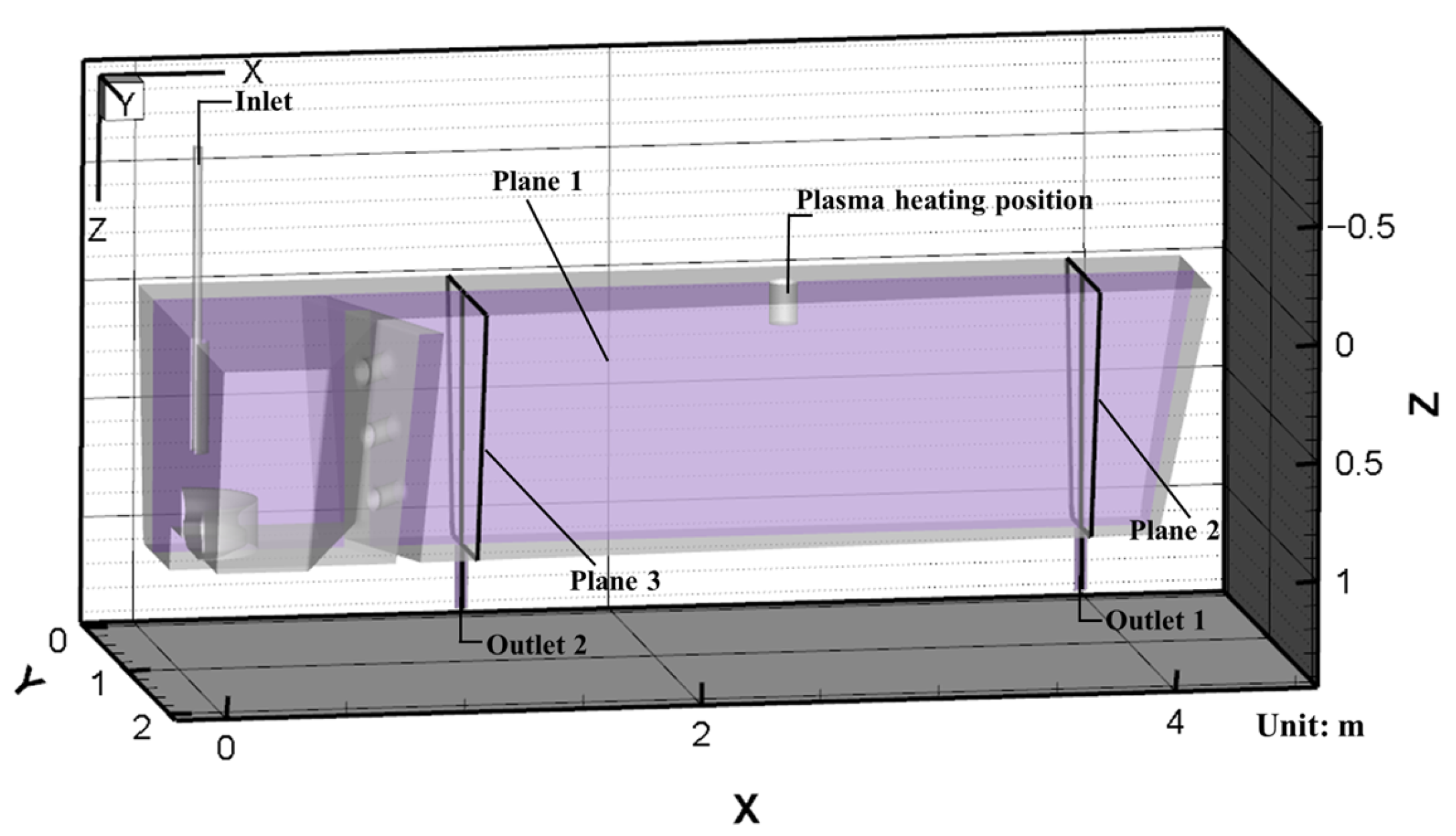
The plasma heating device with three hollow graphite electrodes was introduced to a steelmaking plant and was used to heat the molten steel in a four-strand T-type tundish. Figure 1 presents the schematic diagram of plasma tundish heating in the present study. There is an anode and two cathodes in this system. The tundish capacity is 40 t. The tundish is composed of impact zone and pouring zone. The guide baffles are installed inside the tundish. Figure 2 shows the geometrical model of the four-strand T-type casting tundish with plasma heating. According to the symmetry of the tundish, the 1/2 tundish was selected for simulation calculation. The model completely referred to the prototype parameters and adopted a 1:1 scaling ratio to maximize the simulation of the tundish plasma heating process in the actual production process, and the length of the plasma heating zone is 175 mm. The heating center point is 2650 mm away from the symmetric centerline of the tundish. The specific parameters of the used tundish model are shown in Table 1.

2.2. Meshing

In order to accelerate the calculation speed while ensuring the accuracy of calculation results, the hexahedral structure grid was used in all the computational models in this paper. To obtain the accuracy of the calculation results on inlet, outlets and plasma heating area, the local mesh refinement was applied to these regions. The total number of girds in the computational domain was about 530,000. The overall quality of the grids was better, which was above 0.45.

2.3. Basic Assumptions and Boundary Conditions

The three-dimensional plasma heating four-strand T-type tundish model was based on the following assumptions [16,17,18]:
(1)
The upper part of the tundish was inert gas (Ar), and the influence of the slag layer on heat transfer is not considered;
(2)
The chemical reaction between the phases was not considered;
(3)
Empirical formulas were used for heat dissipation on the wall and top of the tundish, and the second type of wall boundary conditions were used;
(4)
The impact of plasma gas on the molten steel level was negligible, and there was only energy exchange between plasma and molten steel.
The boundary conditions are showed in Table 2.

2.4. Governing Equations

The flow and temperature field change of molten steel in the tundish was an extremely complex process. The numerical model was solved using the commercial software ANSYS Fluent 17.0. The equations describing the flow and temperature field include continuity equation, momentum conservation equation, energy conservation equation and turbulent k–ε equation. The governing equation is as follows [19,20,21]:
(1)
Continuity equation:
ρ t + · ( ρ u i ) = 0
where ρ is the density of the molten steel, and ui is the velocity of the molten steel.
(2)
Momentum conservation equation:
t ( ρ u i ) + · ( ρ u i u j ) = P + μ e f f 2 u i + ρ g i
where P is the static pressure, μeff is the effective viscosity; gi is the gravitational acceleration.
(3)
Energy equation:
C p [ t ( ρ T ) + x i ( ρ T u i ) ] = x i ( λ T x i ) + S T
where T is the temperature of molten steel, λ is the thermal conductivity of molten steel; ST is the viscosity dissipation factor.
(4)
The standard kε model:
( ρ k ) t + ( ρ k u i ) = [ ( μ + μ t σ k ) k ] x i + G k ρ ε
( ρ ε ) t + ( ρ ε u i ) = [ ( μ + μ t σ ε ) ε ] + C 1 ε ε k G k C 2 ε ρ ε 2 k
where k is the turbulent kinetic energy, ε is the turbulent energy dissipation rate, Gk is the turbulence energy under the mean velocity gradient, and is decided by:
G k = ρ u i u j ¯ u i x i
μ t = ρ C μ ( k 2 ε )
The model constants are C1ε = 1.44, C2ε = 1.92, σk = 1.0, Cμ = 0.09, σε = 1.3.

3. Results

3.1. Model Validation

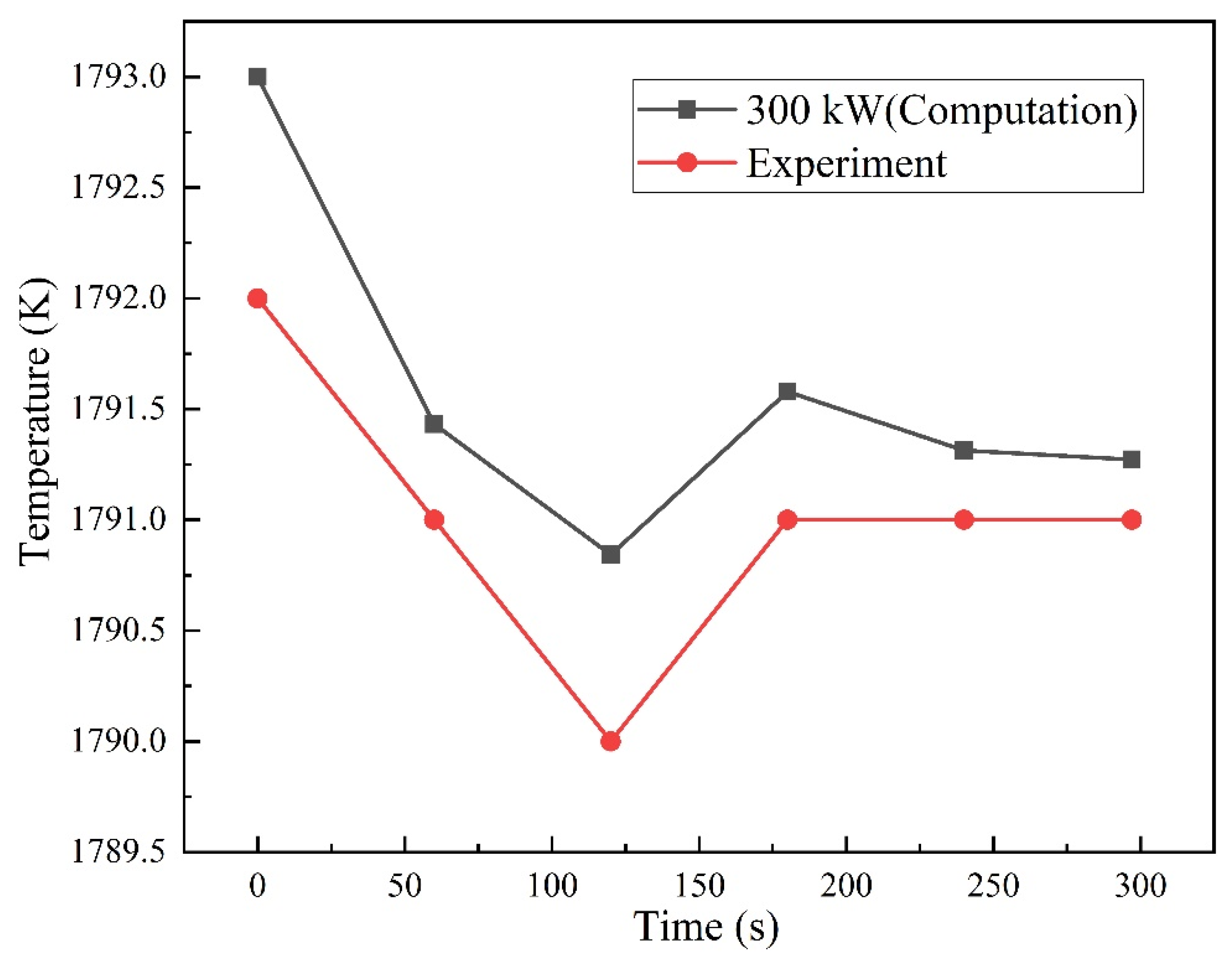
In the present work, the practical industrial temperature data of a four-strand T-type tundish with plasma heating power of 300 kW were measured by the continuous temperature measuring device near the tundish outlet 1. The mathematical model was built on the same geometric dimensions, heating power as the actual tundish. Figure 3 describes the comparison of temperature variation between the experimental and calculation results. The calculation results had a good consistency with the experiment results. Hence, the present mathematic model can be used to explore the plasma heating tundish.

3.2. Flow Field

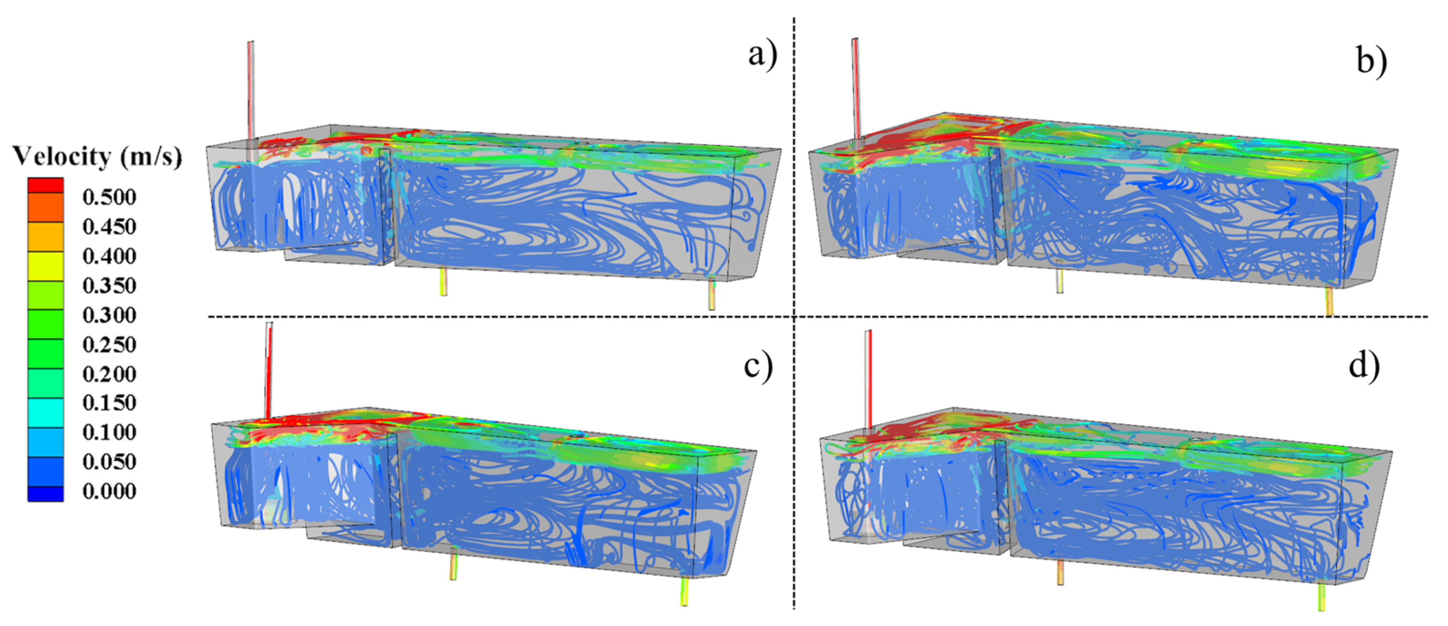
Figure 4 displays the three-dimensional molten steel streamlines in the tundish with different heating powers. It can be seen that without plasma heating, the molten steel flowed out from the diversion hole and then directly flowed out from outlet 2 quickly and formed a short-circuit flow, and less molten steel flowed out from outlet 1. The flow consistency of outlet 1 and outlet 2 was poor. When the tundish was heated by plasma, the flow pattens in 300 kW, 500 kW, and 1000 kW were similar. After the three molten steel streams flowed out from the diversion holes, most of the molten steel flowed a certain distance and then flowed out from the outlet 1. It could eliminate the short-circuit flow at outlet 2, which would improve the uniformity of flow field, and the molten steel near the heating areas tends to flow upward, which prolonged the average residence time of the molten steel and was beneficial to removal inclusions.
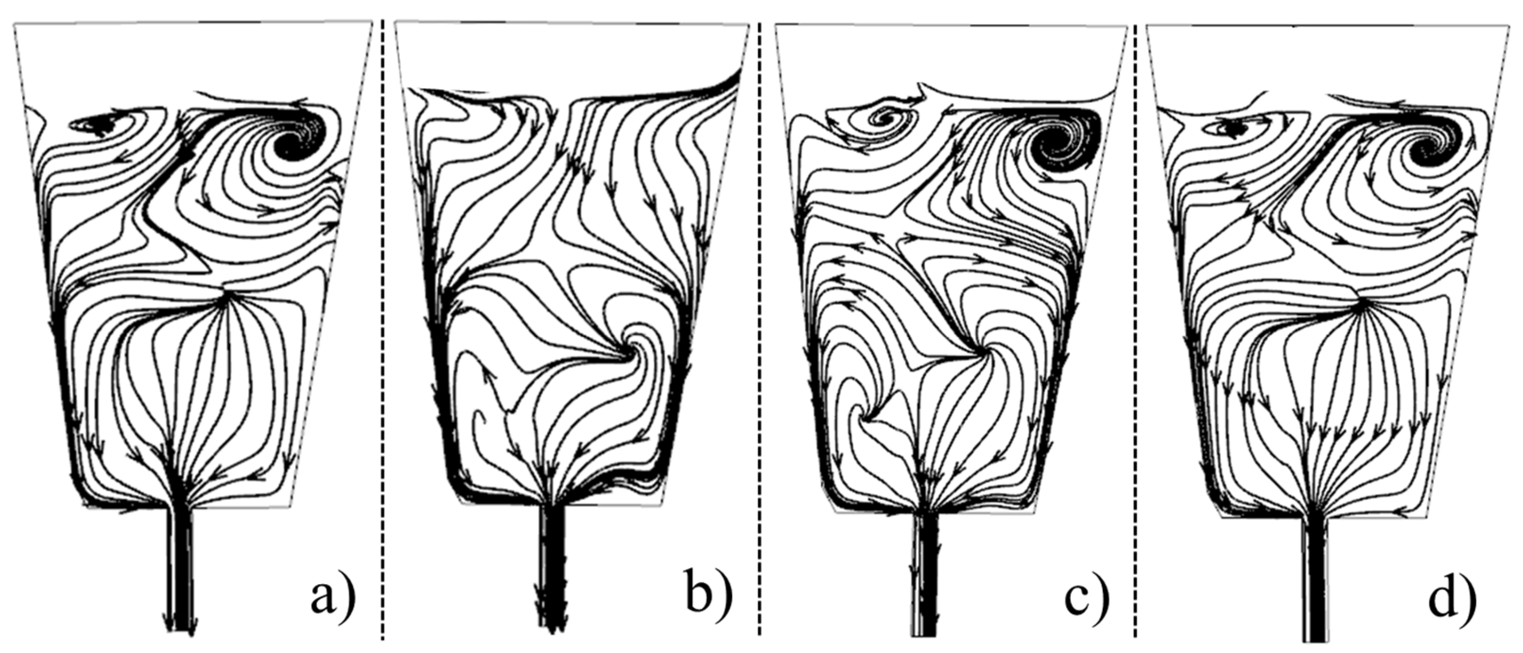
Figure 5 and Figure 6 present the streamlines at plane 2 and plane 3 with different plasma heating powers. As can be seen from the figures, plasma heating could have a big influence on the flow characteristics of molten steel. When the plasma heating was 300 kW, the vortex at plane 2 was eliminated, as shown in Figure 5b. The vortex at plane 3 was enlarged which prolonged the residence time of molten steel. When the plasma heating was 500 kW, the molten steel at plane 2 had an obvious upward flow, which extended the flow path of molten steel and facilitated the floating and removal of inclusions. However, the streamline trends of the molten steel at plane 2 and plane 3 in 1000 kW were similar to that of the prototype tundish.

3.3. Temperature Field

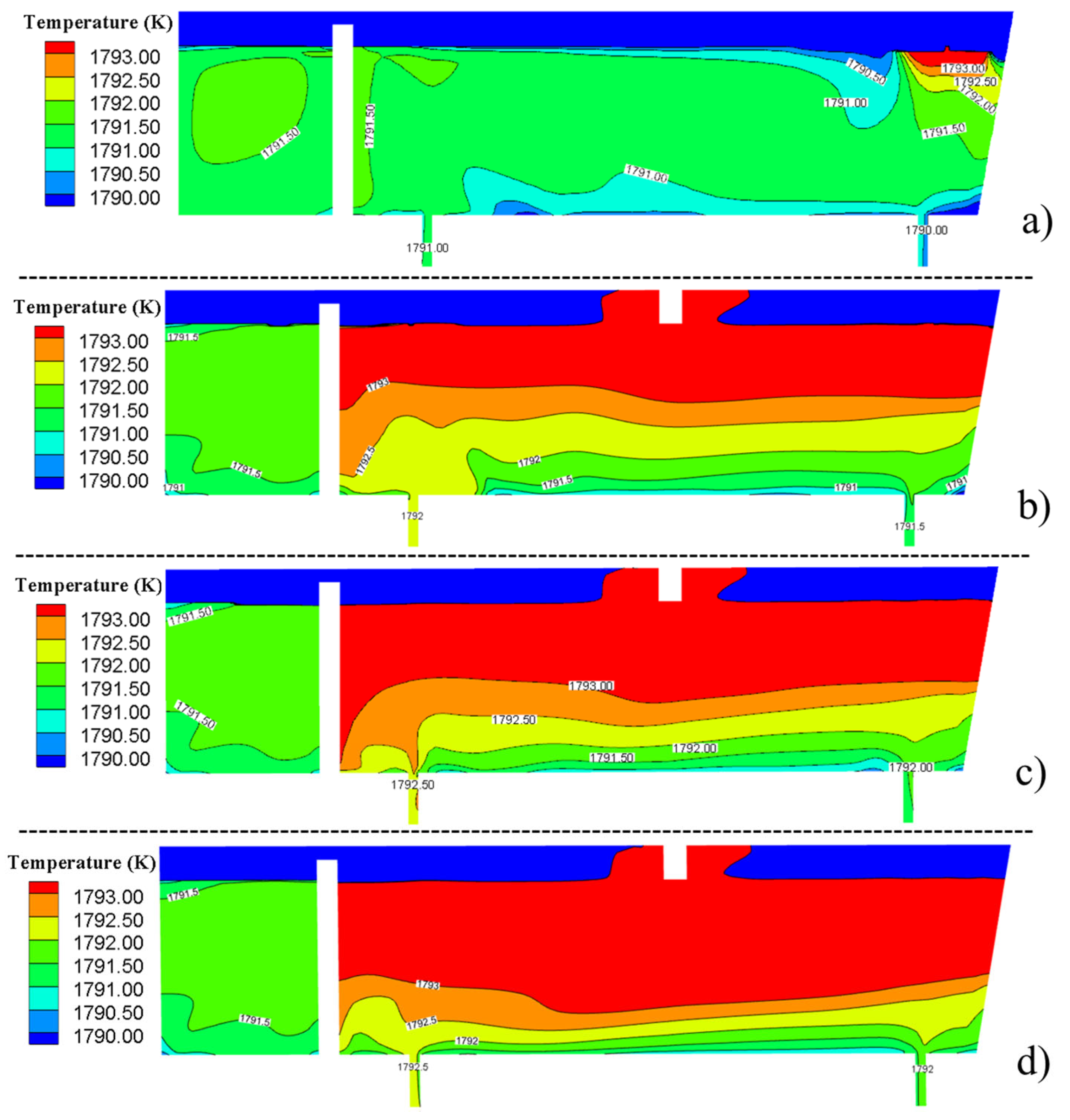
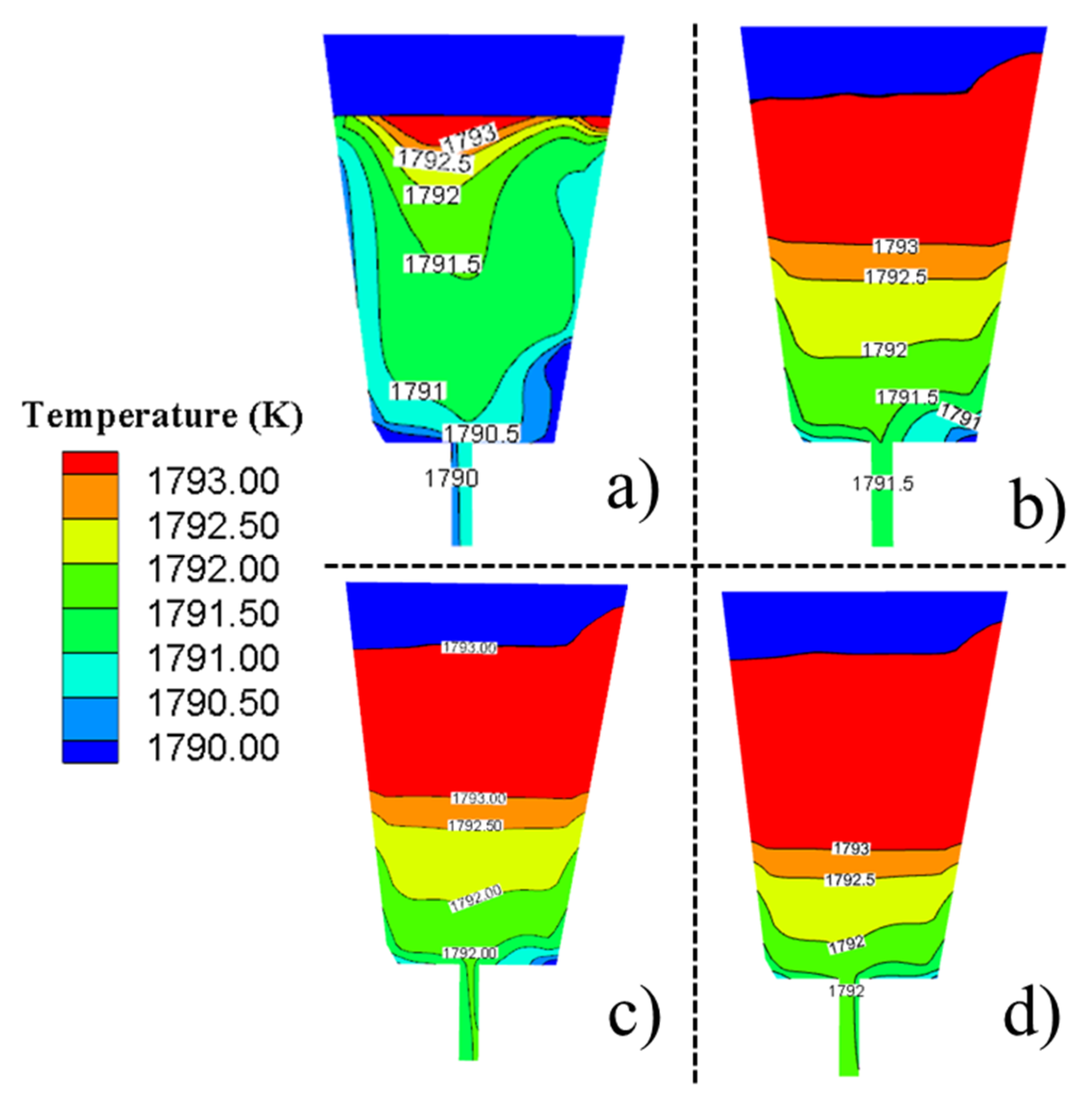
Figure 7 shows the temperature field at plane 1 under different plasma heating powers. Figure 8 and Figure 9 represent the temperature field at plane 2 and plane 3 under different plasma heating powers respectively. It can be seen from the Figure 7a that the overall temperature of the prototype tundish has dropped significantly, especially in the area below the edge of the tundish. This is because most of the molten steel in the tundish does not reach the edge after flowing from the impact zone to the pouring zone. The molten steel flowed directly to outlet 2 resulting in the poor heat exchange between molten steel in the area below the edge and the fresh high temperature molten steel. It can be predicted that the temperature of the molten steel would continue to decrease due to the heat dissipation effect of the wall of the tundish. The high temperature area of the prototype tundish was mainly concentrated in the area above both sides of the tundish. Due to the poor flow of the molten steel in these areas and the heat transfer among the molten steel was weak, the heat accumulated in the upper area of tundish to form a high temperature area. The temperatures at outlet 1 and outlet 2 were dropped by 3 K and 2 K, respectively. The temperature difference between outlet 1 and outlet 2 was 1 K. The temperature was dropped seriously in tundish without plasma heating, which is not conductive to conduct low superheat casting under a constant speed.
It can be seen from the Figure 7a–c that the temperature in the pouring zone was risen significantly. The temperature near the guide baffles could reach nearly 1793 K with plasma heating, which was 1.5 K higher that without plasma heating. The area of 1791.5 K isotherm in pouring zone at the middle of tundish was enlarged with the plasma heating power increasing. The temperature at plasma heating zone was increased at first and then the higher temperature zone extended from top to bottom. The temperature stratification in tundish was obvious. With the increase in the plasma heating power, the range of higher temperature area was enlarged, and it could eliminate the temperature drop at the tundish edge. As shown in Figure 7, the temperature in the areas which was far away from the heating zone was increased slightly, and the area of 1793 K temperature region was larger with the heating power increasing.
It can be observed from Figure 8b–d and Figure 9b–d that although the temperature at plane 3 was higher than that at plane 2, the temperature difference was decreased to 0.5 K. The temperatures at outlets were improved obviously. The temperature at outlet 2 was 1792 K in 500 kW and 1000 kW, which was 2 K higher than that of the prototype tundish. With the increase of plasma heating power, the temperature drop of tundish edge was slow. It can be concluded that the heating effect was remarkable. However, the uniformity of temperature distribution needs to be further optimized. The plasma heating needs to be combined with flow control structure in tundish to enhance the plasma heating effect.
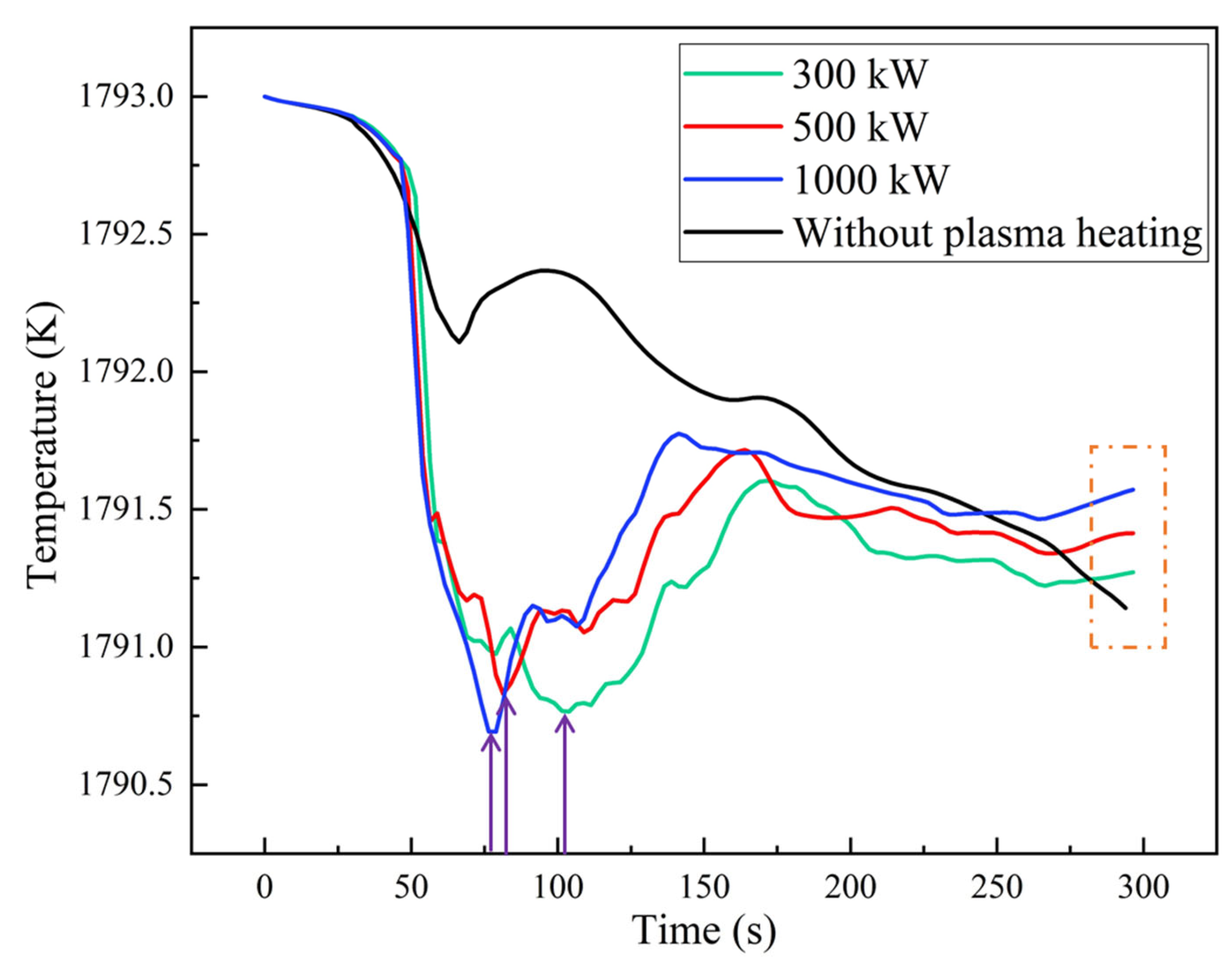
Figure 10 shows temperature variation at outlet 1 under different heating powers. As can be seen, the temperature was in a decreasing state without plasma heating. In 5 min, the temperature was dropped by 1.86 K without plasma heating and it can be assumed that as the pouring process goes on, the temperature will continue to decrease. When the tundish was heated by plasma, the temperature variations had the same trend in 300 kW, 500 kW and 1000 kW. The temperature in outlet 1 was decreased at first with plasma. Outlet 1 was the edge outlet and when the plasma heating started, the flow characteristics of molten steel changed a lot resulting in a big difference in temperature variation at outlet1 between plasma heating and non-plasma heating. However, the reason why the temperature decreased differently at the initial stage of plasma heating needs further study. After 70 s, the temperature was risen. The heating response time at outlet 1 was reduced with an increasing of plasma heating power, as shown by the arrow in Figure 10. The heating rate of molten steel at outlet 1 also was increased with the increasing of heating power. When the plasma heating power was 1000 kW and the heating time was 300 s, the temperature difference was reduced by 23.12% compared with non-plasma heating. It is beneficial to achieve low superheat casting, which could improve the tundish metallurgical effect and improve the slab quality.

3.4. Turbulence Intensity

Figure 11 presents the turbulence intensity of the vertical section at plane 1 in the tundish with different plasma heating powers. As can be seen, the turbulence intensity was changed greatly with plasma heating. When the plasma heating power were 300 kW and 500 kW, the turbulence intensity at side zone in plane 1 was low. The turbulence intensity in 1000 kW was increased and it can be concluded that with an increase in plasma heating power, the turbulence intensity was improved and distributed evenly. As shown in Figure 11, the enhancement of the plasma heating power was conductive to improve the turbulence intensity in tundish, and it would promote the floating removal of inclusions. Moreover, if the flow control structure in tundish would be adjusted according to the plasma heating position, the turbulence intensity distribution in tundish would become better.

4. Conclusions

The effect of the plasma heating power on the flow and temperature field in four-strand T-type tundish for continuous casting were investigated using numerical simulations. The main conclusions were as follows:
(1)
In the prototype tundish without plasma heating, the molten steel flowed out from the diversion hole and then directly flowed out from outlet 2 quickly and formed a short-circuit flow, which results in a poor flow field. The overall temperature of the prototype tundish has dropped significantly. The temperature difference between outlet 1 and outlet 2 was 1 K in 5 min. It can be noted that the temperature of the molten steel would continue to decrease which is not conductive to conduct low superheat casting under a constant speed.
(2)
When the molten steel in tundish heated by plasma, the flow state of molten steel changed greatly. After the three molten steel streams flowed out from the diversion holes, most of the molten steel flowed a certain distance and then flowed out from the outlet 1. It could eliminate the short-circuit flow at outlet 2. When the plasma heating was 500 kW, the molten steel at plane 2 had an obvious upward flow. The turbulence intensity was improved and distributed evenly with an increase in plasma heating power.
(3)
The temperature of molten steel in tundish heated by plasma was risen significantly. The temperature in the upper part of the tundish was maintained above 1793 K, and the low temperature zone at the edge of the tundish was obviously reduced. With the increase of plasma heating power, the volume of high temperature area in tundish was increased and the temperature of outlet was risen obviously. When the plasma heating power was 1000 kW and the heating time was 300 s, the temperature difference was reduced by 23.12% compared with non-plasma heating.

Author Contributions

M.Z. and Y.W. designed the paper; M.Z. and M.Y. did the numerical simulation; all the authors analyzed and discussed the results; M.Z. wrote the paper; S.Y., J.L. and Y.L. revised the paper. All authors have read and agreed to the published version of the manuscript.

Funding

This research was funded by the National Nature Science Foundation of China (Grant No. 52074030, No. 51734003), and the Fundamental Research Funds for the Central Universities (Grant No. FRF-TP-20-008A1).

Data Availability Statement

The raw data required to reproduce these findings cannot be shared at this time as the data also forms part of an ongoing study. The processed data required to reproduce these findings cannot be shared at this time as the data also forms part of an ongoing study.

Conflicts of Interest

The authors declare no conflict of interest.

References

  1. Sahai, Y. Tundish technology for casting clean steel: A review. Metall. Mater. Trans. B 2016, 47, 2095–2106. [Google Scholar] [CrossRef]
  2. Xing, F.; Zheng, S.; Liu, Z.; Zhu, M. Flow Field, Temperature Field, and Inclusion Removal in a New Induction Heating Tundish with Bent Channels. Metals 2019, 9, 561. [Google Scholar] [CrossRef] [Green Version]
  3. Ye, M.; Zhao, M.; Chen, S.; Yang, S.; Li, J. Influence of Plasma Heating on the Metallurgical Effects of a Continuous Casting Tundish. Metals 2020, 10, 1438. [Google Scholar] [CrossRef]
  4. Yang, S.; Zhang, L.; Li, J.; Peaslee, K. Structure optimization of horizontal continuous casting tundishes using mathematical modeling and water modeling. ISIJ Int. 2009, 49, 1551–1560. [Google Scholar] [CrossRef] [Green Version]
  5. Zhi, J.; Zheng, Y.; Cui, J.; Tian, N.; Wu, X.; Xu, A. Temperature measurement and analysis for continuous casting tundish in Baosteel. Iron Steel 2002, 37, 26. [Google Scholar]
  6. Zhao, M.J.; Yang, S.F.; Li, J.S.; Xi, X.J.; Zhang, X.L.; Wang, Y.H.; Chen, Y.F. Effect of plasma heating on the molten steel in Tundish. In Materials Science and Technology 2019; Materials Science and Technology: Portland, OR, USA, 2019. [Google Scholar]
  7. Pan, X.F. Numerical simulation of non-steady fluid flow and heat transfer in continuous casting tundish during series casting. China Metall. 2010, 20, 8. [Google Scholar]
  8. Zuo, Q.W.; An, X.; Yang, J.B.; Cang, D.Q. Effects of over heat and casting speed on quality of GCr15 billet. Adv. Mater. Res. 2014, 3356. [Google Scholar] [CrossRef]
  9. Sun, H.B.; Zhang, J.Q. Macrosegregation improvement by swirling flow nozzle for bloom continuous castings. Metall. Mater. Trans. B 2014, 45, 936–946. [Google Scholar] [CrossRef]
  10. Tian, J.Y.; Zhang, X.L.; Li, J.S.; Wang, X.Z.; Wang, C. Review of Plasma Heating Technology for Continuous Casting Tundish. Wide Heavy Plate 2017, 23, 45–48. [Google Scholar] [CrossRef]
  11. Badie, J.M.; Bertrand, P.; Flamant, G. Temperature distribution in a pilot plasma tundish: Comparison between plasma torch and graphite electrode systems. Plasma Chem. Plasma Process. 2001, 21, 279–299. [Google Scholar] [CrossRef]
  12. Barreto-Sandoval, J.J.; Hills, A.W.S.; Barrón-Meza, M.A.; Morales, R.D. Physical modelling of tundish plasma heating and its mathematical interpretation. ISIJ Int. 1996, 36, 1174–1183. [Google Scholar] [CrossRef]
  13. Barrón-Meza, M.A.; De Barreto-Sandoval, J.; Morales, R.D. Physical and mathematical models of steel flow and heat transfer in a tundish heated by plasma. Metall. Mater. Trans. B 2000, 31, 63–74. [Google Scholar] [CrossRef]
  14. Fan, J.F.; Lu, J.X.; Liu, J.J.; Zhang, W.D. Numerical simulation of the plasma heating process in a six-strand tundish. Acta Metall. Sin. 2001, 37, 429–433. [Google Scholar]
  15. Abiona, E.; Yang, H.L.; Chaudhary, R.; Erikson, J. Development of Plasma Heating and Electromagnetic Stirring in Tundish. In Proceedings of the 8th International Conference on Electromagnetic Processing of Materials, Cannes, France, 12–16 October 2015. [Google Scholar]
  16. Zhang, L.F.; Wang, Y.F.; Zuo, X.J. Flow Transport and Inclusion Motion in Steel Continuous Casting Mold under Submerged Entry Nozzle Clogging Condition. Metall. Mater. Trans. B 2008, 39, 534–550. [Google Scholar] [CrossRef]
  17. Singh, R.K.; Paul, A.; Ray, A.K. Modelling of flow behaviour in continuous casting tundish. Scand. J. Metall. 2010, 32, 137–146. [Google Scholar] [CrossRef]
  18. Ruan, Y.; Yao, Y.; Shen, S.; Wang, B.; Zhang, J.; Huang, J. Physical and Mathematical Simulation of Surface-Free Vortex Formation and Vortex Prevention Design during the End of Casting in Tundish. Steel Res. Int. 2020, 91, 1900616. [Google Scholar] [CrossRef]
  19. Neumann, S.; Asad, A.; Kasper, T.; Schwarze, R. Numerical simulation of metal melt flow in a one-strand tundish regarding active filtration and reactive cleaning. Metall. Mater. Trans. B 2019, 50, 2334–2342. [Google Scholar] [CrossRef]
  20. Ling, H.; Xu, R.; Wang, H.; Chang, L.; Qiu, S. Multiphase flow behavior in a single-strand continuous casting tundish during ladle change. ISIJ Int. 2020, 60, 499–508. [Google Scholar] [CrossRef] [Green Version]
  21. Sheng, D.Y. Mathematical Modelling of Multiphase Flow and Inclusion Behavior in a Single-Strand Tundish. Metals 2020, 10, 1213. [Google Scholar] [CrossRef]
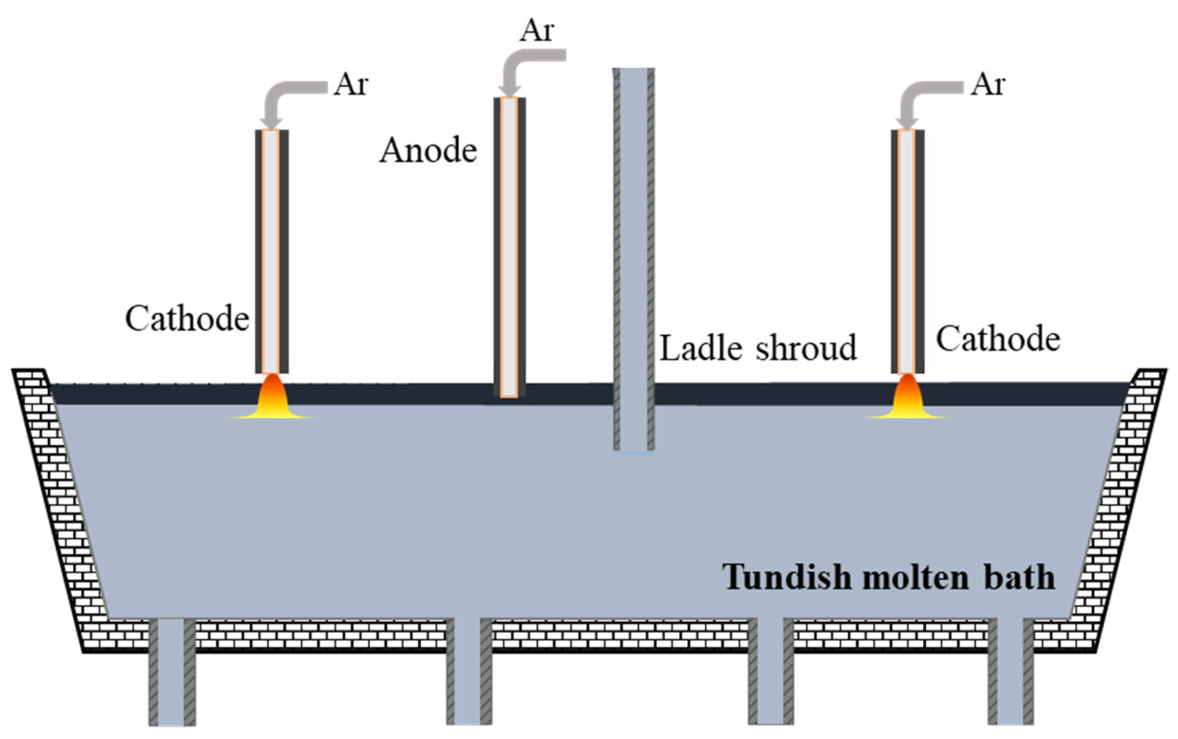
Figure 1. Schematic diagram of tundish plasma heating.
Metals 11 00722 g001
Figure 2. Tundish geometric model and the planes used in the mathematic model.
Metals 11 00722 g002
Figure 3. Comparison of the temperature variation between the experimental and calculation results.
Metals 11 00722 g003
Figure 4. Flow fields with different heating powers. (a) Without plasma heating, (b) 300 kW, (c) 500 kW and (d) 1000 kW.
Metals 11 00722 g004
Figure 5. Streamline at plane 2 under different heating powers. (a) Without plasma heating, (b) 300 kW, (c) 500 kW and (d) 1000 kW.
Metals 11 00722 g005
Figure 6. Streamline at plane 3 under different heating powers. (a) Without plasma heating, (b) 300 kW, (c) 500 kW and (d) 1000 kW.
Metals 11 00722 g006
Figure 7. Temperature fields at plane 1 in tundish heated by plasma under different heating powers. (a) Without plasma heating, (b) 300 kW, (c) 500 kW and (d) 1000 kW.
Metals 11 00722 g007
Figure 8. Temperature fields at plane 2 under different heating powers. (a) non plasma heating, (b) 300 kW, (c) 500 kW and (d) 1000 kW.
Metals 11 00722 g008
Figure 9. Temperature fields at plane 3 under different heating powers. (a) Without plasma heating, (b) 300 kW, (c) 500 kW and (d) 1000 kW.
Metals 11 00722 g009
Figure 10. The temperature at outlet 1 with under different heating powers.
Metals 11 00722 g010
Figure 11. Turbulence intensities of a vertical section in the tundish heated by plasma under different heating powers. (a) Without plasma heating, (b) 300 kW, (c) 500 kW and (d) 1000 kW.
Metals 11 00722 g011
Table 1. The specific parameters of the tundish applied in the calculations.
The Main ParametersValue/mm
Top Width of tundish762.9
Bottom width of tundish427
Top length of tundish4376
Bottom length of the tundish4187
Ladle shroud diameter70
Tundish height1070
Immersion depth of ladle shroud470
Tundish working liquid level height900
Casting speed (m/min)0.4
Table 2. Boundary conditions.
DescriptionValue
Bottom wall heat flux1800 (W·m−2)
Top wall heat flux15,000 (W·m−2)
Longitudinal walls heat flux4200 (W·m−2)
Transversal walls heat flux4000 (W·m−2)
Plasma heating power300 kW/500 kW/1000 kW
Density of molten steel8523–0.8358 T (kg·m−3)
Density of argon1.6228 (kg·m−3)
Viscosity of molten steel0.0061 (kg·m−1·s−1)
Viscosity of argon0.0000212 (kg·m−1·s−1)
Thermal conductivity of molten steel41 (W·m−1·k−1)
Thermal conductivity of argon0.0158 (W·m−1·k−1)
Specific heat of molten steel750 (kg·m−1·s−1)
Specific heat of argon520.64 (kg·m−1·s−1)
Initial temperature of molten stee1793 K
Calculation time 5 min
Publisher’s Note: MDPI stays neutral with regard to jurisdictional claims in published maps and institutional affiliations.