Article

Compression Behaviour of Wire + Arc Additive Manufactured Structures

1
Institute of Product and Process Innovation, Leuphana University of Lueneburg, Universitatsallee 1, 21335 Lueneburg, Germany
2
Helmholtz-Zentrum Hereon, Institute of Materials Mechanics, Max-Planck-Straße 1, 21502 Geesthacht, Germany
3
Welding Engineering and Laser Processing Centre, Cranfield University, Cranfield MK43 0AL, UK
4
WAAM3D Ltd., 5 Thornton Chase, Milton Keynes MK14 6FD, UK
*
Author to whom correspondence should be addressed.
Metals 2021, 11(6), 877; https://doi.org/10.3390/met11060877
Submission received: 24 March 2021 / Revised: 11 May 2021 / Accepted: 13 May 2021 / Published: 27 May 2021

Abstract

:
Increasing demand for producing large-scale metal components via additive manufacturing requires relatively high building rate processes, such as wire + arc additive manufacturing (WAAM). For the industrial implementation of this technology, a throughout understanding of material behaviour is needed. In the present work, structures of Ti-6Al-4V, AA2319 and S355JR steel fabricated by means of WAAM were investigated and compared with respect to their mechanical and microstructural properties, in particular under compression loading. The microstructure of WAAM specimens is assessed by scanning electron microscopy, electron back-scatter diffraction, and optical microscopy. In Ti-6Al-4V, the results show that the presence of the basal and prismatic crystal planes in normal direction lead to an anisotropic behaviour under compression. Although AA2319 shows initially an isotropic plastic behaviour, the directional porosity distribution leads to an anisotropic behaviour at final stages of the compression tests before failure. In S355JR steel, isotropic mechanical behaviour is observed due to the presence of a relatively homogeneous microstructure. Microhardness is related to grain morphology variations, where higher hardness near the inter-layer grain boundaries for Ti-6Al-4V and AA2319 as well as within the refined regions in S355JR steel is observed. In summary, this study analyzes and compares the behaviour of three different materials fabricated by WAAM under compression loading, an important loading condition in mechanical post-processing techniques of WAAM structures, such as rolling. In this regard, the data can also be utilized for future modelling activities in this direction.

1. Introduction

Wire + arc additive manufacturing (WAAM) has gained attention from industry due to its ability to produce large near-net-shape products at low cost and high deposition rates [1]. The process uses an electric arc as heat source to deposit a metal wire as feedstock in a layer-by-layer manner. A Large Additive Subtractive Integrated Modular Machine (LASIMM) has been developed in the European project LASIMM [2]. This project is using the high deposition rate capability of WAAM to produce large scale engineering structures, combined with machining, and with inter-layer cold working, such as rolling, to provide materials with properties beyond those of forged or wrought materials [3,4]. Through the rolling process, the material is deformed under compression; this has several benefits, such as improvement in mechanical properties [4,5,6], microstructural refinement [3,6], elimination of porosity [5,6], and reduction/control of residual stresses [7,8,9]. Hence, understanding how the materials that are deposited by WAAM behave under compression is crucial. In this regard, this study investigates the mechanical behaviour of WAAM-fabricated materials under compression loading.
Structural alloys such as titanium [10], steel [11], aluminum [5], or nickel-based [12] ones are the most typical materials that have been successfully processed by WAAM. In case of titanium alloys, Ti-6Al-4V is the most used alloy in the aerospace industry [13,14] due to its high strength-to-weight ratio, good fatigue properties and excellent corrosion resistance [15]. Steel has maintained its position as the predominant material for automotive and construction industries, owing to its good formability, ease of welding, and relatively low cost [16]. The unique combination of low-cost, low density, and high strength [17] has made aluminum alloys the preferred materials for applications where weight reduction is vital, such as in the automotive and aerospace industries [18].
During the WAAM process, the material undergoes complex thermal cycles with a directional heat extraction [19]. This typically causes the formation of columnar grains resulting in anisotropic and heterogeneous microstructures [20,21,22]. Furthermore, porosity formation and its non-uniform distribution [23] might also cause anisotropy in WAAM-fabricated aluminum alloys [24]. Anisotropic tensile mechanical properties have been extensively reported in the literature for WAAM-fabricated structures [4,25,26], as well as other additive manufactured (AM) parts [20,21]. The anisotropy of mechanical properties in AM Ti-6Al-4V, such as in the ultimate tensile strength, is explained by the presence of columnar grains in the as-fabricated structures [27], whilst the anisotropy in ductility is associated with grain boundary regions that are prone to damage accumulation [20,28,29]. The mechanical properties of WAAM-fabricated aluminum alloys during tensile testing are typically described as nearly isotropic [25,26]. Zhang et al. [24] found that the WAAM-fabricated Al-6Mg alloy shows an anisotropic behaviour in terms of tensile strength, ranging from 8 % to 27 % . The anisotropic behaviour is explained by the presence of pores that are formed in the inter-layer regions [23,24]. From this short literature review, it is seen that the presence of columnar grains and porosity is one of the main sources for the observed anisotropy in WAAM-processed materials.
To minimize the appearance of welding defects such as pores or hot cracks, as well as to suppress the formation of coarse-grained as-cast microstructures of WAAM-fabricated structures, different advanced variants of the technology have been recently developed. One way is to combine an in situ hot forging technique to WAAM to refine the grain structure and to reduce porosity and therefore to improve the mechanical properties of the deposited layers [30]. The formation of fine-grained macrostructure with reduced anisotropy can also be controlled by the use of advanced WAAM processes combined with an active cooling technique [31,32] or to reduce the thermal impact during the process, such as in the case of the new variant defined as Ultracold-wire + arc additive manufacturing (UC-WAAM) [33]. Next to using advanced process variants, the process optimization in general is a challenging task, as typically a large number of process parameters influence the resulting microstructure and properties. In this regard, to predict the process–microstructure-property relationship in additive manufacturing or other processes, in order to optimize the process in an efficient way, machine learning approaches are very promising [34,35]. However, the appearance of manufacturing defects such as porosity or hot cracks cannot be completely eliminated in most cases [36]. Therefore, WAAM fabricated parts in general require post-process treatment that can also improve material properties, reduce surface roughness, and remove residual stress and distortions [36].
There are several post-processing treatment technologies that are employed to eliminate the defects in WAAM-fabricated parts, e.g., heat treatment [37], inter-pass cold rolling [38], and inter-pass cooling [39]. The tensile mechanical behaviour of AM structures has been frequently reported in the literature [25,26,40,41,42,43,44]. However, in the context of mechanical treatments, such as rolling [7], machine hammer peening [45] and laser shock peening [46], the mechanical behaviour of materials under compressive load is important. There are only a few studies in the literature that investigate the mechanical behaviour of AM structures during compression in detail [47,48]. Improving this understanding will enable the optimisation of cold-work processes in terms of their application strategy. Consequently, one aim of this study is the investigation of the mechanical properties of WAAM-fabricated Ti-6Al-4V, S355JR steel, and AA2319 during compression.
The manuscript is structured as follows: In Section 2, the experimental techniques used for the manufacturing of the additive structures as well as for microstructural and mechanical characterisation are briefly described. The mechanical behaviour of WAAM-fabricated Ti-6Al-4V, AA2319 and S355JR steel during compression for three orthogonal loading directions is studied in Section 3 to investigate possible anisotropy. First, the stress–strain response of each of the three materials during compression testing is analyzed, followed by a discussion of the obtained mechanical behaviour in correlation with the present microstructural features. The main conclusions of the study are briefly summarized in Section 4.

2. Experimental Procedure

2.1. WAAM Process

The WAAM specimens of the three different materials—Ti-6Al-4V, AA2319 and S355JR steel—were built using a robotic system with integrated welding process equipment. The chemical compositions of the used wires are given in Table 1.
Ti-6Al-4V structure was deposited on a 12 mm thick plate of the same alloy using wire and an EWM T552 Tetrix plasma power source (EWM AG, Mündersbach, Germany). To prevent oxidation of the specimens, these were deposited in a tent chamber with all pure-shield argon ( 99.99 % ) that guaranteed a residual oxygen content between 200 and 600 ppm. The shielding gas flow is comparably low (see Table 2) because it was done with the aid of an additional local shielding device based on [49]. After deposition, the specimens were removed from the substrate and a stress-relieving heat treatment was applied for 4 h at 650 C in an inert argon atmosphere.
A Fronius Cold Metal Transfer (CMT) advanced 4000R power source (Fronius International GmbH, Pettenbach, Austria) was used for the deposition of both AA2319 and S355JR steel. The pulsed CMT mode (CMT-P) and standard CMT mode (continuous current) were used for AA2319 and S355JR steel, respectively. The specimens were built on 12.6 mm thick substrates of compatible alloy grades—AA2219-T6 and S355JR steel—and pure-shield argon (99.99%) was employed as shielding gas. No heat treatment was applied after deposition of AA2319 and S355JR steel. The full list of the deposition parameters for each material is summarized in Table 2.
As the final dimensions of the specimens required a width of 20 mm, 4 overlapping beads were deposited in parallel with a determined spacing between them to guarantee no fusion defects. For Ti-6Al-4V and AA2319 samples, this spacing was 4 mm, while for S355JR a spacing of 5 mm was used. When starting the deposition of a subsequent layer, the deposition direction was reversed and the end of the previous layer was the starting point of the new one.

2.2. Microstructural Investigation

The microstructures of the WAAM-fabricated materials in the as-deposited state were investigated using optical microscope (OM) Leica DMI5000 M (Leica Microsystems GmbH, Wetzlar, Germany) as well as a scanning electron microscope (SEM) (JEOL JSM-6490LV, Jeol Ltd., Tokyo, Japan) combined with electron back scattering diffraction (EBSD) (DigiView 3 camera, TSL OIM Data Collection 5.31, OIM Analysis 5.31) to describe microstructural morphology and to determine local micro-texture at different areas. For this purpose, samples were extracted from the WAAM-fabricated blocks, fixed, finely ground with SiC sandpaper in several stages, polished, and etched. Etched samples were used for optical microscopic examinations, and EBSD analyses were performed on polished specimens. Preliminary EBSD investigations revealed that the microstructure of the WAAM samples of Ti-6Al-4V, AA2139, and S355JR are characterized by a weak micro-texture and do not exhibit any preferential orientations. Furthermore, the absence of orthorhombic sample symmetry is evident. For this reason, the micro-texture of the WAAM samples was determined using inverse pole figures (IPF), and calculation of IPF was conducted based on the generalized spherical harmonic expansion (GSHE) method, whereas triclinic sample symmetry was assumed. The EBSD measurements were performed covering a specimen area of 950 μ m × 950 μ m, at 30 kV, beam current of 3.5 nA, emission current of 71 μ A −74 μ A, magnification of 100×, working distance of 14 mm, step size of 2.00 μ m, and sample tilt of 70 . The EBSD analyses were carried out at several positions in such a way that the respective examined microstructural areas overlap and are merged into an overall picture. Thus, a statistically relevant number of single orientations was measured. The fixed directions of [001], [010] and [100] are parallel to the transverse (TD), normal (ND) and longitudinal (LD) directions, respectively, as defined in Figure 1.

2.3. Compression Test

For the compression tests, three cylindrical specimens in each direction with a diameter of 10 mm and a height of 15 mm were extracted from the WAAM-produced wall-like structures. In Figure 1, the schematic of the direction of the specimens is shown. The longitudinal and normal directions represent the deposition and building directions, respectively, and the transverse direction is perpendicular to the longitudinal-normal plane.
The titanium specimens were tested in a servo-hydraulic testing machine from Schenck-Instron (Instron GmbH, Darmstadt, Germany) with a maximum loading capacity of 1000 kN. Due to the expected lower load necessary to test the aluminum and steel specimens, the Zwick 1484 universal testing machine (Zwick Roell Group, Ulm, Germany) with a maximum load of 200 kN was used. The deformation velocities were 0.1 mm/min and 0.5 mm/min in case of Ti-6Al-4V and 0.5 mm/min in case of AA2319 and S355JR steel. Teflon spray was used to minimize friction between the surface of the samples and the compression die. Deformation of the specimens was measured in the servo-hydraulic testing machine via MTS clips for displacement measurements (Model 632.03C-31, MTS Sensor Technologie GmbH & Co. KG, Lüdenscheid, Germany) and on the Zwick 1484 universal testing machine by the laser scanner system Fiedler WS180 (Fiedler Optoelektronik GmbH, Lützen, Germany). All tests were carried out at room temperature, and at least five samples were tested of each material.

2.4. Microhardness Test

The microhardness tests were performed along the normal and transverse directions in the normal-transverse cross-sections for all three materials using the automated Vickers hardness testing machine FALCON 5000 (INNOVATEST Europe BV, Maastricht, The Netherlands). In each direction, at least three measurements were conducted in representative areas of the WAAM-fabricated materials, such as in the layer bands as well as inter-layer boundaries. It should be mentioned that different indentation distances were chosen for different materials. The indentation was carried out with a load of 0.3 kg for Ti-6Al-4V as well as S355JR steel and 0.2 kg for AA2319.

3. Results and Discussion

3.1. Ti-6Al-4V

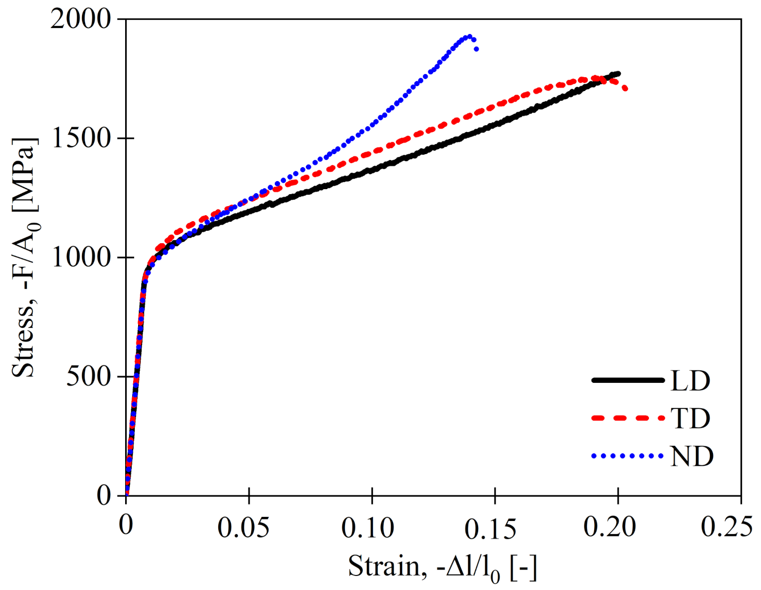
In Figure 2, the stress–strain response of WAAM-fabricated Ti-6Al-4V during compressive loading in three orthogonal directions (longitudinal, transverse and normal) is shown, and the key properties are summarized in Table 3. As can be seen from Figure 2, WAAM-fabricated Ti-6Al-4V shows approximately the same behaviour during compression in longitudinal and transverse directions, but the behaviour obtained in normal direction is different. Similar observations regarding the orientation-dependent mechanical properties of AM Ti-6Al-4V parts during tensile testing have been reported in the literature [42,43,44]. The reason has been explained by the loading direction with respect to the direction of elongated prior β -grains and microstructural texture.
Therefore, the detected direction-dependent mechanical behaviour is attributed to the microstructure of WAAM-fabricated Ti-6Al-4V. The Ti-6Al-4V microstructure consists of several layers and is characterized by a domain structure containing α lamellae; see Figure 3. Grain boundary α phase is also observed within the prior β -grains. It should be mentioned that similar microstructures have been reported by [10,22] for WAAM-fabricated Ti-6Al-4V. The color coding in the crystal orientation map shows that the crystal directions of the α lamellae are very different in relation to the transverse sample direction [001]; see Figure 4. The present representation shows a manifold of orientations, which is typical for solidification structures in Ti-6Al-4V. From this, it can be deduced that there were no pronounced preferential directions for both heat conduction and crystal growth in the microstructure region shown. The statistical determination of lamella width and lamella length was carried out on the basis of Figure 4. At the build-up height, the lamella length varied in a range between 16.4 μ m and 20.7 μ m, and the lamella width in a range between 4.1 μ m and 5.5 μ m. This resulted in aspect ratios of the lamella from 0.31 to 0.35.
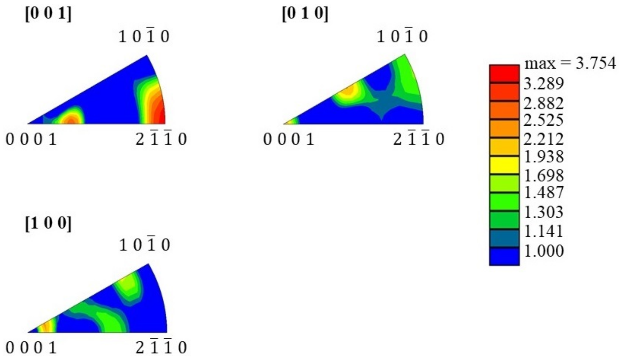
The inverse [ 001 ] pole figure (transverse direction) shows the occurrence of axial intensities at 2 1 ¯ 1 ¯ 0 with a spread angle to 0001 as well as 10 1 ¯ 0 and 2 1 ¯ 2 ¯ 5 ; see Figure 5. The Taylor factor is M [ 001 ] = 4.19 ± 0.59 .
The inverse [ 100 ] pole figure (longitudinal direction) shows an orientation band between 2 1 ¯ 1 ¯ 2 and 10 1 ¯ 7 as well as between 10 1 ¯ 2 and 6 3 ¯ 3 ¯ 5 . Furthermore, a spread at 20 2 ¯ 1 is present. The spreading angles with respect to the axial intensities of the inverse pole figures are correspondingly pronounced. Another typical feature is the formation of domains in which the fine lamellae are grouped together.
The Taylor factor is M [ 100 ] = 4.23 ± 0.72 , which is slightly higher than the one obtained in the transverse direction. In the longitudinal direction [100], crystal directions appear that are closer to the 0001 corner or 10 1 ¯ 0 corner of the inverse [100] pole figure. It can therefore be assumed that shear stresses on the basal and prismatic planes are lower than in the transverse direction [001]. Correspondingly higher compressive forces are required to activate dislocations with the Burgers vector c + a .
The inverse [010] pole figure (normal direction) shows axial intensities at 0001 , 10 1 ¯ 0 , and 0001 corner or 70 7 ¯ 9 crystal directions; see Figure 5. The Taylor factor M [ 010 ] = 4.32 ± 0.74 is slightly higher compared to other two loading directions. In the case of crystal directions 0001 / / [ 010 ] and 10 1 ¯ 0 / / [ 010 ] , the test direction is perpendicular to the basal plane ( 0001 ) or prismatic plane ( 10 1 ¯ 0 ) . In this orientation, the Burgers vectors a and c cannot be activated because these Burgers vectors are parallel to the basal or prismatic plane, and the respective shear stresses are zero. The determined Taylor factor for direction [010] indicates that dislocations with a Burgers vector c + a must be activated. Higher compressive forces compared to the [100] direction are required to mobilize dislocations with a Burgers vector c + a . The crystal direction 70 7 ¯ 9 / / [ 010 ] is between 0001 and 10 1 ¯ 0 at about 45 . In this direction, a sliding on the basal plane is easier to activate.
According to Taylor’s theory [50], at least five independent slip systems are required for homogeneous deformation. To ensure the compatibility of the polycrystalline deformation, it is necessary to additionally activate the c + a -slip systems, if the test direction is perpendicular to the basal plane or prismatic plane. As already mentioned, higher compressive forces are required for the activation of the c + a sliding. Therefore, it is assumed here that c + a -sliding has to be activated when compressive loading is applied in normal and longitudinal directions, and consequently the compressive strength values are higher in these directions than in the transverse direction. The difference between the Taylor factors is not significant, which is also reflected in the small differences in the yield strength for all three loading directions. Significant differences are also not expected because the texture sharpness of the WAAM structure of Ti-6Al-4V is low. The standard deviations are due to the average grain sizes of the alpha lamellae in combination with the magnification of 100 times on the SEM. The crystallographic orientation differences between normal, longitudinal, and transverse sample directions are clear and are correlated to the Taylor factors.
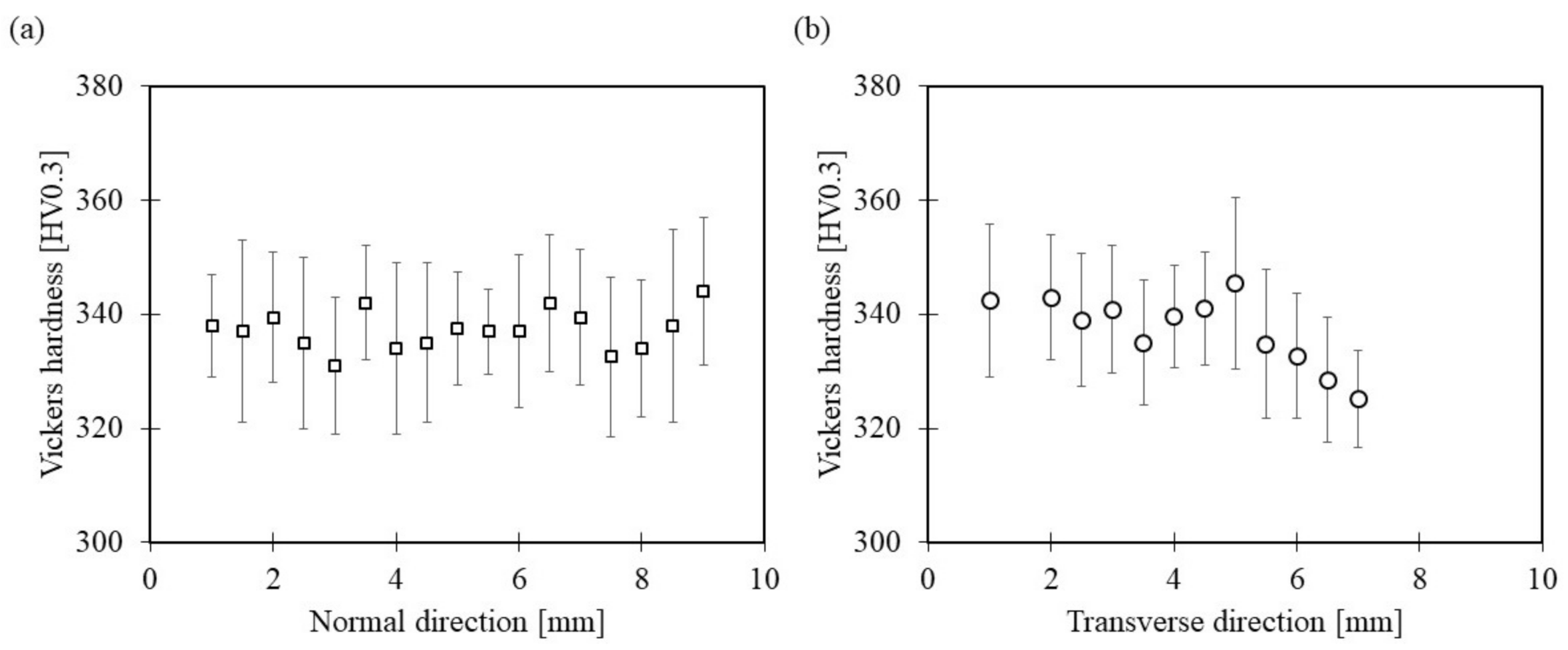
In Figure 6, the hardness results for WAAM-fabricated Ti-6Al-4V are shown. The hardness is 332 ± 12.55 HV0.3 and 337 ± 11.31 HV0.3 in the normal and transverse direction, respectively, which is lower than the hardness level of Ti-6Al-4V according to the ASTM international standard, which is 365 HV [51]. The hardness variations in normal direction are due to the layer-like structure of the WAAM Ti-6Al-4V microstructure. In transverse direction, the hardness decreases by increasing the height of structure at 5 mm, which indicates that the cooling rates were lower, which may result in coarsening of the grains. As already discussed in the literature [3,22], the thickness of the α lamellae changes with the height of a deposited layer, resulting in a change in hardness of the material along the layer height, with higher value of the hardness near the interfaces between the different deposited layers, i.e., the so-called layer bands [22].

3.2. AA2319

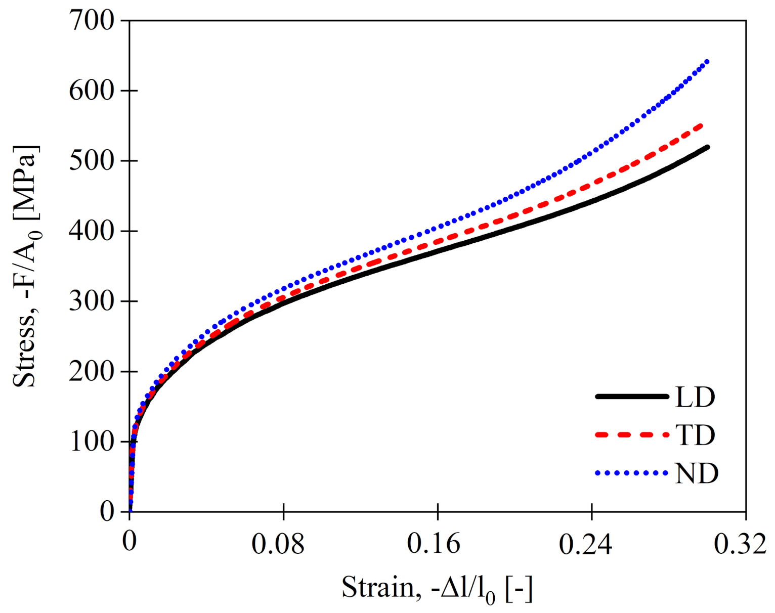
The compressive stress–strain responses of WAAM-fabricated AA2319 for three orthogonal directions are displayed in Figure 7, while the determined mechanical properties are summarized in Table 4. The results indicate that the elastic modulus is slightly varying in all three loading directions. The reason is attributed to the level of porosity that is contained in the WAAM specimens. During compressive loading, porosity furthermore leads to the reduction in effective load-bearing cross-sectional area and single pores might act as a stress concentration sites for strain localization that results in a decrease in ductility overall [52].
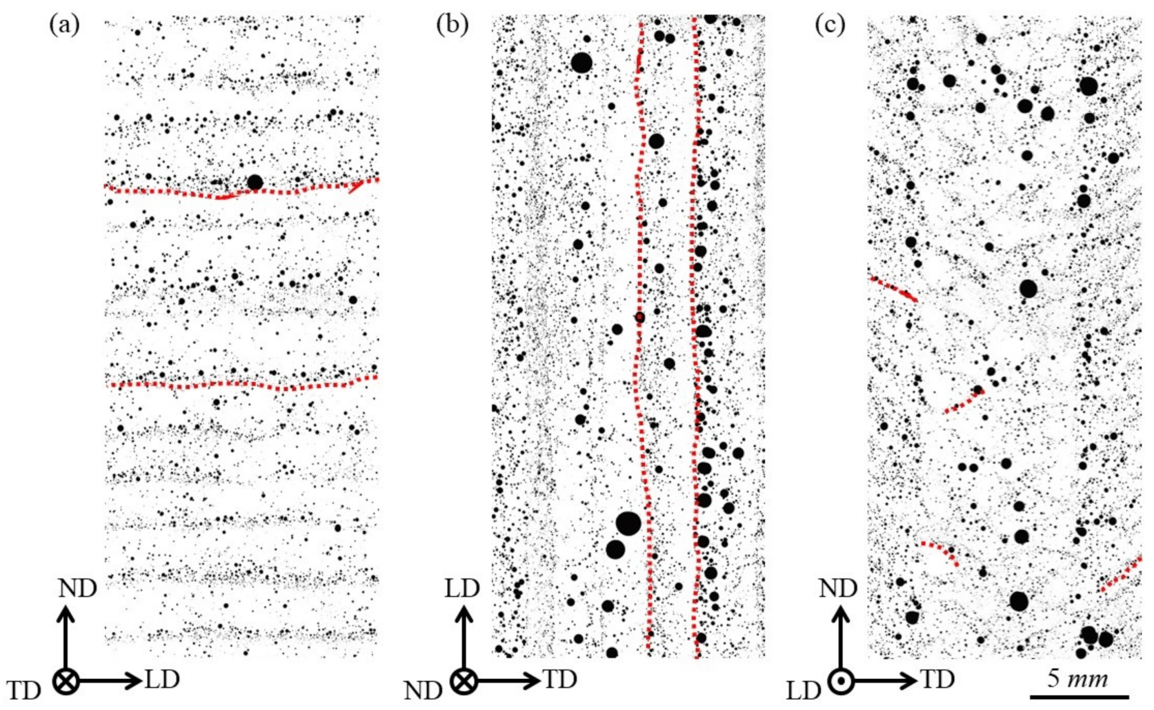
The porosity distribution in a WAAM processed AA2319 specimen is shown in Figure 8 for the relevant cross-sections. Selected representative inter-layer boundaries are highlighted for the reader’s convenience. The presence of porosity in WAAM-fabricated AA2319 is typically attributed either to not-fully-optimized process conditions, which is classified as process-induced porosity [53], or the wire quality, which is classified as material-induced porosity [54]. The moisture, grease, and hydrocarbon contaminations present on the wire surface are vaporized by arc heat and absorbed in the molten pool as atomic hydrogen [55]. The directional formation of the pores in WAAM-fabricated AA2319 can clearly be seen in Figure 8.
The mechanical behaviour of WAAM-fabricated AA2319 is nearly isotropic in the early stages of the plastic deformation; see Figure 7. The isotropy of tensile mechanical properties of AM aluminum alloys has been widely reported in the literature [25,26,40]. For instance, Bai et al. [26] reported 1% anisotropy of ultimate tensile strength for AA2219 produced by AM with tungsten inert gas.
The crystal orientation map within a layer of WAAM-fabricated AA2319 is shown in Figure 9. As seen in this figure, grain morphology varies from large columnar grains in the inner layer part to very fine equiaxed grains in the inter-layer boundaries. Randomized grain shape in the compression samples implies that the grain morphology has no effect on the mechanical properties of the WAAM-fabricated AA2319. Furthermore, no crystallographic preferential orientations are recognizable, so in the case of the WAAM AA2319 structure, there is also a weak texture.
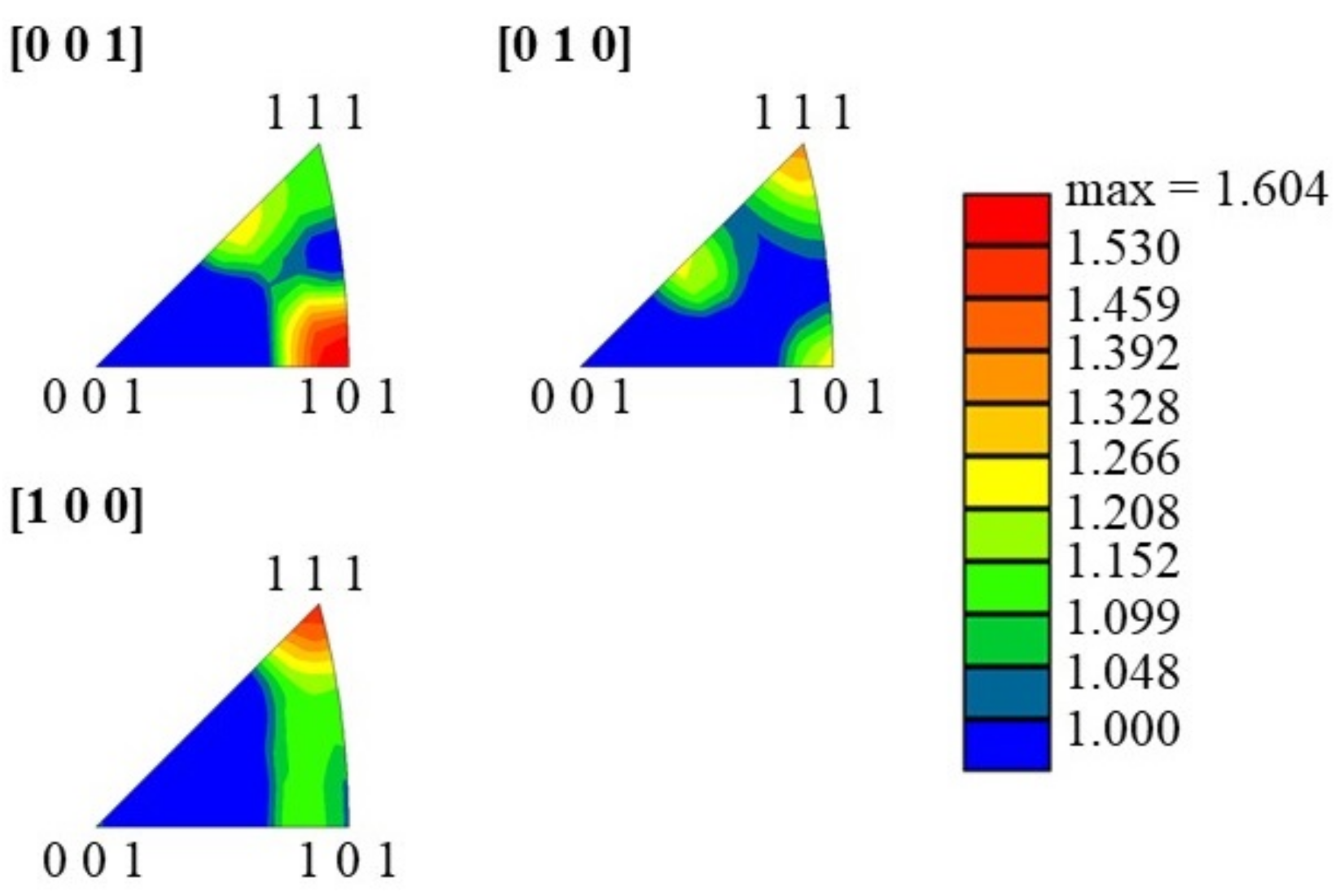
The IPF for all three loading directions are shown in Figure 10. The inverse [001] pole figure shows that the majority of crystals are oriented in 101 direction with slight distribution in 334 , as well as 111 . The inverse [010] pole figure shows local distribution of crystal orientations in 101 , 334 , and 111 , whilst an orientation band between 111 and 101 is observed in the inverse [100] pole figure. Although the preferred crystal orientations are varying for the different directions, WAAM AA2319 shows approximately isotropic behaviour in different directions during the compression tests; see Figure 7. The reason is that the compressive force mainly interacts with the (111) and (110) planes in all sample directions. Therefore, the calculated Taylor factors regarding the different sample directions show approximately similar values of M [ 001 ] = 3.15 ± 0.39 , M [ 010 ] = 3.09 ± 0.39 , and M [ 100 ] = 3.12 ± 0.40 . This can explain the similar onset of the yielding of WAAM AA2319 in the three different orthogonal loading directions (see Table 4), where the slight differences, as in case of the Young’s modulus, are mainly porosity-related.
The mechanical behaviour of WAAM AA2319 shows an anisotropic behaviour for increased deformation; in particular, the response in normal direction deviates from the other loading directions. This is most likely due to the directional distribution of pores. As discussed earlier, the pores are mostly located in the inter-layer boundaries, which can be referred to as linear porosity [56]; see Figure 8. The compressive samples extracted from the longitudinal direction contains a bundle of linear porosity aligned in this direction. During compressive loading in the longitudinal direction, this linear porosity acts as weak linear sites where damage is preferentially accumulated. As a result, layers can slide on each other during loading. In contrast, during the deformation in the transverse and normal directions, layers are compressed on each other, resulting in higher compressive strengths compared to the longitudinal direction.
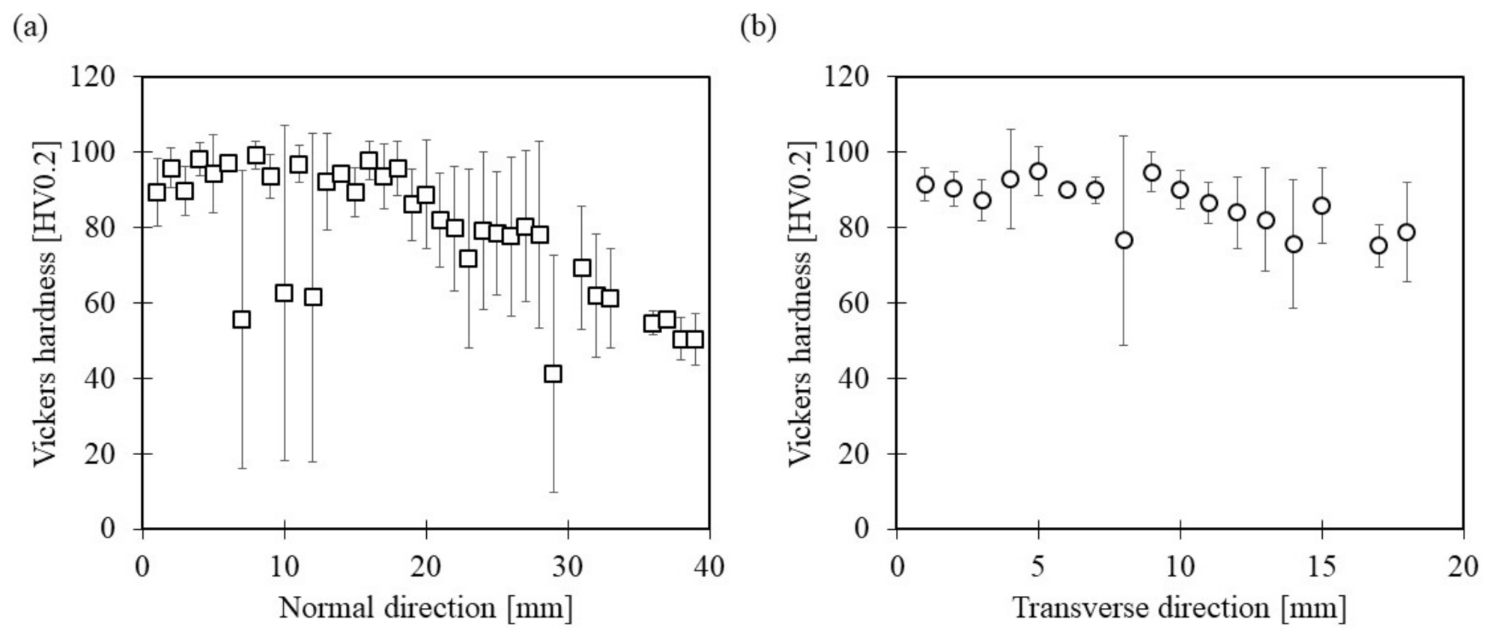
The microhardness test results of WAAM AA2319 in both normal and transverse directions are shown in Figure 11. The microhardness is determined to be 76.2 ± 21.42 HV0.2 and 86.02 ± 12.52 HV0.2 in normal and transverse directions, respectively. These values make it appear that the microhardness is higher in transverse direction. However, the microhardness values drop at some locations in normal direction due to the presence of pores around the indent. This consequently affects the mean value of the hardness in normal direction. It can be seen that the hardness is changing along the normal and transverse directions. As discussed before, the grain morphology as well as grain size is changing within the layer of WAAM AA2319; see Figure 9. Finer grains lead to more grain boundaries, which results in higher microhardness by enhancing the material’s ability to resist deformation. In the normal direction, hardness drops with gaining height of the structure. In the beginning of the process, heat dissipates into the base plate, and smaller grains are formed. After a stable heat conduction up to 18 mm, hardness drops, which is a sign that the weld cooled more slowly, forming larger grains.

3.3. S355JR Steel

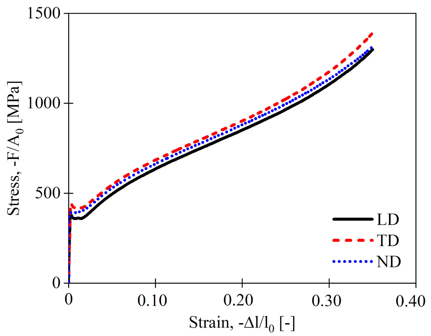
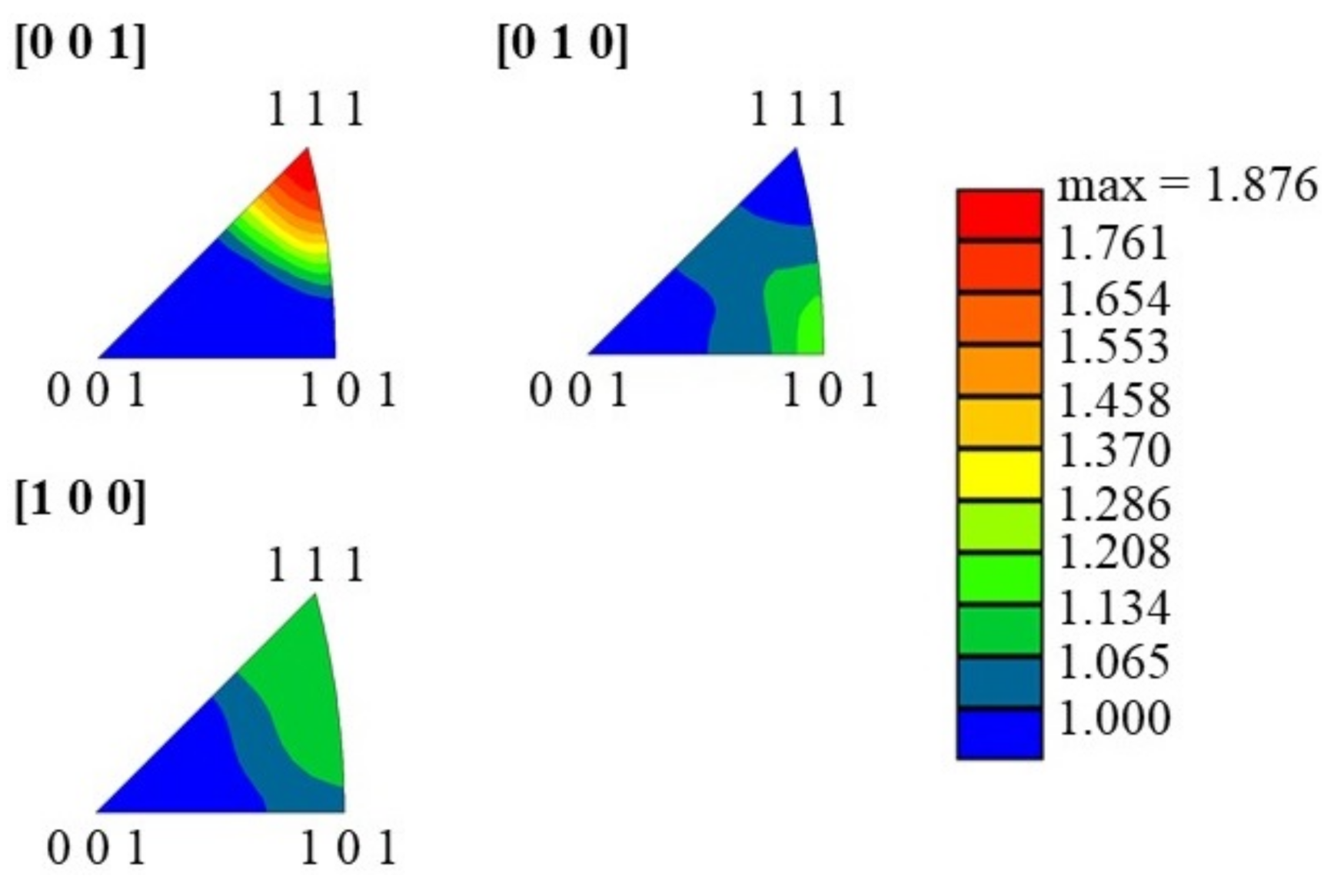
In Figure 12, the stress–strain responses of WAAM S355JR steel for loading in longitudinal, normal, and transverse directions during compression are shown. As summarized in Table 5, the mechanical properties of WAAM S355JR steel are nearly isotropic due to the presence of a relatively homogeneous microstructure. The grain size distribution and orientation maps of WAAM S355JR steel are shown in Figure 13. The microstructure contains refined and non-refined regions where it has been stated by Colegrove et al. [7] that the refined region represents the majority of the microstructure in the case of WAAM S355JR steel. This is also the typical microstructure of ASTM international standard S355JR steel [57]. The grains are nearly equiaxed in both refined and non-refined regions. Shassere et al. [41] found that the mechanical properties of WAAM low carbon steel are isotropic in the middle of the build, where the microstructure is fairly homogeneous. Small deviations in compressive mechanical properties can be rationalized by the presence of different amounts of non-refined regions in different samples. In Figure 14, the inverse pole figures of the WAAM S355JR steel for the three loading directions are shown. The WAAM S355JR steel is characterized by a pronounced (111)//[111] fiber texture. The comparison of the Taylor factors shows approximately similar values of M [ 001 ] = 3.13 ± 0.39 , M [ 010 ] = 3.09 ± 0.39 , M [ 100 ] = 3.10 ± 0.38 in the corresponding testing directions. This also explains the approximately equal yield strength for all directions as listed in Table 5.
In Figure 15, the microhardness distribution for WAAM-fabricated S355JR steel is shown for the transverse and normal direction. The hardness is 152.4 ± 5.82 HV0.3 and 150.51 ± 4.95 HV0.3 in normal and transverse directions, respectively, which is lower than the hardness level of S355JR UNI EN 10025 low carbon steel [58], which is about 167 HV. The microhardness changes slightly in both transverse and normal directions. This is attributed to the change of the microstructure from refined grains in inner-layer parts to the non-refined region in layer bands; see Figure 13. As discussed earlier, finer grains result in higher hardness due to the presence of higher number of grain boundaries that increase the ability of the material to resist the deformation.

4. Conclusion Remarks

The relationship between the microstructural features, i.e., grain morphology as well as crystallographic orientation and compressive mechanical properties as well as microhardness of WAAM-fabricated Ti-6Al-4V, AA2319, and S355JR steel were investigated.
It is well-known that the material’s mechanical properties are controlled by their deformation mechanism, which are the result of microstructure and crystal orientation. On the other hand, the microstructural features such as grain morphology and crystallographic orientation are the result of processing of the material. The WAAM-fabricated Ti-6Al-4V contains very fine lamellae grains where no dominant orientation exists in the microstructure. For WAAM-fabricated AA2319, the morphological features of the grains such as grain size and shape are locally changing within the layer. However, in the scale of the compression samples in this study, all types of grain morphologies are present. WAAM-fabricated S355JR steel contains non-refined and refined regions, where the refined microstructure is the major one.
The restricted number of available slip systems in H C P metals, such as Ti-6Al-4V, usually makes the accommodation of homogeneously strains through dislocation slip difficult. In case of aluminum and steel with F C C and B C C crystal structures, respectively, there are several slip systems that possess the required five independent slip systems that permit their grains to deform homogeneously. The results of this study are summarized as follows:
  • In case of WAAM-fabricated Ti-6Al-4V, due to the presence of basal and prismatic crystal planes in normal direction, the a -slip on basal and c -slip on prismatic planes cannot be activated during compression, which leads to the highest compressive strength and lowest deformation when loaded in the normal direction.
  • WAAM-fabricated AA2319 and S355JR steel exhibit isotropic mechanical behaviour in all directions. However, directional formation of the porosity in AA2319 causes anisotropic behaviour in the last stages of the deformation during compression. The porosity also results in a slight anisotropy of the elastic modulus.
  • Microhardness changes in the normal and transverse direction of all three materials are mainly the result of grain morphology variations. The layer-like structure of the WAAM-fabricated Ti-6Al-4V, AA2319, and S355JR steel leads to different grain morphologies in inner-layer regions and inter-layer boundaries. The microhardness has higher value near the inter-layer boundaries of WAAM Ti-6Al-4V and AA2319 as well as refined regions in WAAM S355JR steel. Crystallographic orientation distribution does not seem to affect the microhardness.

Author Contributions

Conceptualization, S.R., N.K., and B.K.; methodology, V.V. and S.R.; formal analysis, V.V.; investigation, V.V., L.N., S.R., and J.H.; resources, N.K. and S.W.; data curation, M.A. and V.V.; writing—original draft preparation, M.A. and V.V.; writing—review and editing, M.A., V.V., L.N., F.M., N.K., S.W., and B.K.; visualization, M.A. and V.V.; supervision, N.K. and B.K.; project administration, N.K. and B.K.; funding acquisition, S.W. and B.K. All authors have read and agreed to the published version of the manuscript.

Funding

This project has received funding from the European Union’s Horizon 2020 research and innovation programme in the project LASIMM (Large Additive Subtractive Integrated Modular Machine) under grant agreement No 723600 which is gratefully acknowledged.
Metals 11 00877 i001

Data Availability Statement

The data presented in this study are available upon reasonable request from the corresponding author.

Acknowledgments

The authors thank Falk Dorn and Mirko Erdmann for their contribution in experimental tests.

Conflicts of Interest

The authors declare no conflict of interest.

Abbreviations

A 0 initial specimen cross section
EYoung’s modulus
E c compressive Young’s modulus
Fforce
lspecimen length
l 0 initial specimen length
σ d 30 , σ d 35 strength at compressive strain of 30% and 35%, respectively
σ u ultimate compressive strength
σ y compressive yield strength
AMadditive manufacturing
B C C body-centered cubic
CMTcold metal transfer
CMT-Ppulsed CMT mode
DCdirect current
EBSDelectron back scattering diffraction
F C C face-centered cubic
GSHEgeneralized spherical harmonic expansion
H C P hexagonal close packed
IPFinverse pole figure
LASIMMLarge Additive Subtractive Modular Machine
LDlongitudinal direction
NDnormal direction
OMoptical microscope
RDrolling direction
SEMscanning electron microscope
TDtransverse direction
UC-WAAMultracold-wire + arc additive manufacturing
WAAMwire + arc additive manufacturing

References

  1. Williams, S.W.; Martina, F.; Addison, A.C.; Ding, J.; Pardal, G.; Colegrove, P.A. Wire + Arc Additive Manufacturing. J. Mater. Sci. Technol. 2016, 32, 641–647. [Google Scholar] [CrossRef] [Green Version]
  2. LASIMM Project. Available online: http://www.lasimm.eu (accessed on 23 April 2021).
  3. Martina, F.; Colegrove, P.A.; Williams, S.W.; Meyer, J. Microstructure of Interpass Rolled Wire + Arc Additive Manufacturing Ti-6Al-4V Components. Metall. Mater. Trans. A 2015, 46, 6103–6118. [Google Scholar] [CrossRef] [Green Version]
  4. Martina, F.; Williams, S.W.; Colegrove, P.A. Improved Microstructure and Increased Mechanical Properties of Additive Manufacture Produced Ti-6Al-4V by Interpass Cold Rolling. In Proceedings of the 24th International Solid Freeform Fabrication Symposium, Austin, TX, USA, 4–6 August 2013; pp. 490–496. [Google Scholar]
  5. Gu, J.; Ding, J.; Williams, S.W.; Gu, H.; Ma, P.; Zhai, Y. The Strengthening Effect of Inter-Layer Cold Working and Post-Deposition Heat Treatment on the Additively Manufactured Al–6.3Cu Alloy. Mater. Sci. Eng. A 2016, 651, 18–26. [Google Scholar] [CrossRef] [Green Version]
  6. Gu, J.; Wang, X.; Bai, J.; Ding, J.; Williams, S.W.; Zhai, Y.; Liu, K. Deformation Microstructures and Strengthening Mechanisms for the Wire+ Arc Additively Manufactured Al-Mg4.5Mn Alloy with Inter-Layer Rolling. Mater. Sci. Eng. A 2018, 712, 292–301. [Google Scholar] [CrossRef]
  7. Colegrove, P.A.; Coules, H.E.; Fairman, J.; Martina, F.; Kashoob, T.; Mamash, H.; Cozzolino, L.D. Microstructure and Residual Stress Improvement in Wire and Arc Additively Manufactured Parts through High-Pressure Rolling. J. Mater. Process. Technol. 2013, 213, 1782–1791. [Google Scholar] [CrossRef]
  8. Hönnige, J.R.; Colegrove, P.A.; Ganguly, S.; Eimer, E.; Kabra, S.; Williams, S.W. Control of Residual Stress and Distortion in Aluminium Wire + Arc Additive Manufacture with Rolling. Addit. Manuf. 2018, 22, 775–783. [Google Scholar] [CrossRef] [Green Version]
  9. Hönnige, J.R.; Colegrove, P.A.; Ahmad, B.; Fitzpatrick, M.E.; Ganguly, S.; Lee, T.L.; Williams, S.W. Residual Stress and Texture Control in Ti-6Al-4V Wire+ Arc Additively Manufactured Intersections by Stress Relief and Rolling. Mater. Des. 2018, 150, 193–205. [Google Scholar] [CrossRef] [Green Version]
  10. Wang, F.; Williams, S.W.; Colegrove, P.A.; Antonysamy, A.A. Microstructure and Mechanical Properties of Wire and Arc Additive Manufactured Ti-6Al-4V. Metall. Mater. Trans. A 2013, 44, 968–977. [Google Scholar] [CrossRef]
  11. Yilmaz, O.; Ugla, A.A. Microstructure Characterization of SS308LSi Components Manufactured by GTAW-Based Additive Manufacturing: Shaped Metal Deposition using Pulsed Current Arc. Int. J. Adv. Manuf. Technol. 2017, 89, 13–25. [Google Scholar] [CrossRef]
  12. Asala, G.; Khan, A.K.; Andersson, J.; Ojo, O.A. MicroStructural Analyses of ATI 718Plus® Produced by Wire-Arc Additive Manufacturing Process. Metall. Mater. Trans. A 2017, 48, 4211–4228. [Google Scholar] [CrossRef] [Green Version]
  13. Boyer, R.R. An Overview on the use of Titanium in the Aerospace Industry. Mater. Sci. Eng. A 1996, 213, 103–114. [Google Scholar] [CrossRef]
  14. Peters, M.; Kumpfert, J.; Ward, C.H.; Leyens, C. Titanium Alloys for Aerospace Applications. Adv. Eng. Mater. 2003, 5, 419–427. [Google Scholar] [CrossRef]
  15. ASTM B367-13, Standard Specification for Titanium and Titanium Alloy Castings; ASTM: Pittsburgh, PA, USA, 2017.
  16. Davis, J.R. ASM Specialty Handbook: Carbon and Alloy Steels; ASM International: Pittsburgh, PA, USA, 1996. [Google Scholar]
  17. Davis, J.R. Alloying: Understanding the Basics; ASM International: Materials Park, OH, USA, 2001; pp. 359–360. [Google Scholar]
  18. Das, S.K.; Yin, W. The worldwide aluminum economy: The current state of the industry. J. Miner. Met. Mater. Soc. 2007, 59, 57–63. [Google Scholar] [CrossRef]
  19. Shifeng, W.; Shuai, L.; Qingsong, W.; Yan, C.; Sheng, Z.; Yusheng, S. Effect of Molten Pool Boundaries on the Mechanical Properties of Selective Laser Melting Parts. J. Mater. Process. Technol. 2014, 214, 2660–2667. [Google Scholar] [CrossRef]
  20. Carroll, B.E.; Palmer, T.A.; Beese, A.M. Anisotropic Tensile Behavior of Ti–6Al–4V Components Fabricated with Directed Energy Deposition Additive Manufacturing. Acta Mater. 2015, 87, 309–320. [Google Scholar] [CrossRef]
  21. Kok, Y.; Tan, X.P.; Wang, P.; Nai, M.L.S.; Loh, N.H.; Liu, E.; Tor, S.B. Anisotropy and Heterogeneity of Microstructure and Mechanical Properties in Metal Additive Manufacturing: A critical Review. Mater. Des. 2018, 139, 565–586. [Google Scholar] [CrossRef]
  22. Ho, A.; Zhao, H.; Fellowes, J.W.; Martina, F.; Davis, A.E.; Prangnell, P. On the Origin of Microstructural Banding in Ti-6Al-4V Wire-Arc Based High Deposition Rate Additive Manufacturing. Acta Mater. 2019, 166, 306–323. [Google Scholar] [CrossRef]
  23. Bai, J.; Ding, H.L.; Gu, J.L.; Wang, X.S.; Qiu, H. Porosity Evolution in Additively Manufactured Aluminium Alloy during High Temperature Exposure. IOP Conf. Ser. Mater. Sci. Eng. 2017, 167. [Google Scholar] [CrossRef] [Green Version]
  24. Zhang, C.; Li, Y.; Gao, M.; Zeng, X. Wire arc additive manufacturing of Al-6Mg alloy using variable polarity cold metal transfer arc as power source. Mater. Sci. Eng. A 2018, 711, 415–423. [Google Scholar] [CrossRef]
  25. Fang, X.; Zhang, L.; Li, H.; Li, C.; Huang, K.; Lu, B. Microstructure Evolution and Mechanical Behavior of 2219 Aluminum Alloys Additively Fabricated by the Cold Metal Transfer Process. Materials 2018, 11, 812. [Google Scholar] [CrossRef] [Green Version]
  26. Bai, J.Y.; Yang, C.L.; Lin, S.B.; Dong, B.L.; Fan, C.L. Mechanical Properties of 2219-Al Components Produced by Additive Manufacturing with TIG. Int. J. Adv. Manuf. Technol. 2016, 86, 479–485. [Google Scholar] [CrossRef]
  27. Bian, L.; Thompson, S.M.; Shamsaei, N. Mechanical Properties and MicroStructural Features of Direct Laser-Deposited Ti-6Al-4V. J. Miner. Met. Mater. Soc. 2015, 67, 629–638. [Google Scholar] [CrossRef]
  28. Simonelli, M.; Tse, Y.Y.; Tuck, C. Effect of the Build Orientation on the Mechanical Properties and Fracture Modes of SLM Ti-6Al-4V. Mater. Sci. Eng. A 2014, 616, 1–11. [Google Scholar] [CrossRef] [Green Version]
  29. Ladani, L.; Razmi, J.; Choudhury, S.F. Mechanical Anisotropy and Strain Rate Dependency Behavior of Ti6Al4V Produced using E-Beam Additive Fabrication. J. Eng. Mater. Technol. 2014, 136, 1–7. [Google Scholar] [CrossRef]
  30. Duarte, V.R.; Rodrigues, T.A.; Schell, N.; Miranda, R.M.; Oliveira, J.P.; Santos, T.G. Hot forging wire and arc additive manufacturing (HF-WAAM). Addit. Manuf. 2020, 35, 101193. [Google Scholar] [CrossRef]
  31. Scotti, F.M.; Teixeira, F.R.; da Silva, L.J.; de Araujo, D.B.; Reis, R.P.; Scotti, A. Thermal management in WAAM through the CMT Advanced process and an active cooling technique. J. Manuf. Process. 2020, 57, 23–35. [Google Scholar] [CrossRef]
  32. da Silva, L.J.; Souza, D.M.; de Araujo, D.B.; Reis, R.P.; Scotti, A. Concept and validation of an active cooling technique to mitigate heat accumulation in WAAM. Int. J. Adv. Manuf. Technol. 2020, 107, 2513–2523. [Google Scholar] [CrossRef]
  33. Rodrigues, T.A.; Duarte, V.R.; Miranda, R.M.; Santos, T.G.; Oliveira, J.P. Ultracold-Wire and Arc Additive Manufacturing (UC-WAAM). J. Mater. Process. Technol. 2021, 117196. [Google Scholar] [CrossRef]
  34. Tomaz, I.V.; Colaço, F.H.G.; Sarfraz, S.; Pimenov, D.Y.; Gupta, M.K.; Pintaude, G. Investigations on quality characteristics in gas tungsten arc welding process using artificial neural network integrated with genetic algorithm. Int. J. Adv. Manuf. Technol. 2021, 113, 3569–3583. [Google Scholar] [CrossRef]
  35. Bock, F.E.; Aydin, R.C.; Cyron, C.J.; Huber, N.; Kalidindi, S.R.; Klusemann, B. A Review of the Application of Machine Learning and Data Mining Approaches in Continuum Materials Mechanics. Front. Mater. 2019, 6, 110. [Google Scholar] [CrossRef] [Green Version]
  36. Wu, B.; Pan, Z.; Ding, D.; Cuiuri, D.; Li, H.; Xu, J.; Norrish, J. A review of the wire arc additive manufacturing of metals: Properties, defects and quality improvement. J. Manuf. Process. 2018, 35, 127–139. [Google Scholar] [CrossRef]
  37. Brandl, E.; Baufeld, B.; Leyens, C.; Gault, R. Additive Manufactured Ti-6Al-4V using Welding Wire: Comparison of Laser and Arc Beam Deposition and Evaluation with Respect to Aerospace Material Specifications. Phys. Procedia 2010, 5, 595–606. [Google Scholar] [CrossRef] [Green Version]
  38. Donoghue, J.; Antonysamy, A.A.; Martina, F.; Colegrove, P.A.; Williams, S.W.; Prangnell, P.B. The Effectiveness of Combining Rolling Deformation with Wire-Arc Additive Manufacture on β-Grain Refinement and Texture Modification in Ti-6Al-4V. Mater. Charact. 2016, 114, 103–114. [Google Scholar] [CrossRef]
  39. Wu, B.; Pan, Z.; Ding, D.; Cuiuri, D.; Li, H.; Fei, Z. The Effects of Forced Interpass Cooling on the Material Properties of Wire Arc Additively Manufactured Ti6Al4V Alloy. J. Mater. Process. Technol. 2018, 258, 97–105. [Google Scholar] [CrossRef] [Green Version]
  40. Domack, M.S.; Taminger, K.M.B.; Begley, M. Metallurgical Mechanisms Controlling Mechanical Properties of Aluminium Alloy 2219 Produced by Electron Beam Freeform Fabrication. Mater. Sci. Forum 2006, 1291–1296. [Google Scholar] [CrossRef]
  41. Shassere, B.; Nycz, A.; Noakes, M.W.; Masuo, C.; Sridharan, N. Correlation of Microstructure and Mechanical Properties of Metal big Area Additive Manufacturing. Appl. Sci. 2019, 9, 787. [Google Scholar] [CrossRef] [Green Version]
  42. Vilaro, T.; Colin, C.; Bartout, J.D. As-Fabricated and Heat-Treated Microstructures of the Ti-6Al-4V Alloy Processed by Selective Laser Melting. Metall. Mater. Trans. A 2011, 42, 3190–3199. [Google Scholar] [CrossRef]
  43. Rafin, H.K.; Karthik, N.V.; Gong, H.; Starr, T.L.; Stucker, B.E. Microstructures and Mechanical Properties of Ti6Al4V Parts Fabricated by Selective Laser Melting and Electron Beam Melting. J. Mater. Eng. Perform. 2013, 22, 3872–3883. [Google Scholar] [CrossRef]
  44. Hrabe, N.; Quinn, T. Effects of Processing on Microstructure and Mechanical Properties of a Titanium Alloy (Ti-6Al-4V) Fabricated using Electron Beam Melting (EBM), Part 2: Energy Input, Orientation, and Location. Mater. Sci. Eng. A 2013, 573, 271–277. [Google Scholar] [CrossRef]
  45. Hönnige, J.R.; Colegrove, P.A.; Williams, S.W. Improvement of Microstructure and Mechanical Properties in Wire + Arc Additively Manufactured Ti-6Al-4V with Machine Hammer Peening. Procedia Eng. 2017, 216, 8–17. [Google Scholar] [CrossRef]
  46. Guo, W.; Sun, R.; Song, B.; Zhu, Y.; Li, F.; Che, Z.; Guo, B.L.C.; Liu, L.; Peng, P. Laser Shock Peening of Laser Additive Manufactured Ti6Al4V Titanium Alloy. Surf. Coat. Technol. 2018, 349, 503–510. [Google Scholar] [CrossRef]
  47. Schulze, C.; Weinmann, M.; Schweigel, C.; Kessler, O.; Bader, R. Mechanical Properties of a Newly Additive Manufactured Implant Material Based on Ti-42Nb. Materials 2018, 11, 124. [Google Scholar] [CrossRef] [Green Version]
  48. Losertova, M.; Kubes, V. Microstructure and Mechanical Properties of Selective Laser Melted Ti6Al4V Alloy. IOP Conf. Ser. Mater. Sci. Eng. 2017, 266. [Google Scholar] [CrossRef]
  49. Ding, J.; Colegrove, P.; Martina, F.; Williams, S.; Wiktorowicz, R.; Palt, M.R. Development of a laminar flow local shielding device for wire+ arc additive manufacture. J. Mater. Process. Technol. 2015, 226, 99–105. [Google Scholar] [CrossRef]
  50. Taylor, G.I. Plastic Strain in Metals. J. Inst. Met. 1938, 62, 307–324. [Google Scholar]
  51. Boyer, R.; Welsch, G.; Collings, E.W. Materials Properties Handbook: Titanium Alloys; ASM International: Materials Park, OH, USA, 1998. [Google Scholar]
  52. Hardin, R.A.; Cong, C.B. Effect of Porosity on the Stiffness of Cast Steel. Metall. Mater. Trans. A 2007, 38, 2992–3006. [Google Scholar] [CrossRef]
  53. Cong, B.; Ding, J.; Williams, S.W. Effect of Arc Mode in Cold Metal Transfer Process on Porosity of Additively Manufactured Al-6.3%Cu Alloy. Int. J. Adv. Manuf. Technol. 2015, 76, 1593–1606. [Google Scholar] [CrossRef]
  54. Ryan, E.M.; Sabin, T.J.; Watts, J.F.; Whiting, M.J. The Influence of Build Parameters and Wire Batch on Porosity of Wire and Arc Additive Manufactured Aluminium Alloy 2319. J. Mater. Process. Technol. 2018, 262, 577–584. [Google Scholar] [CrossRef]
  55. Gu, J.; Ding, J.; Williams, S.W.; Gu, H.; Ma, P.; Zhai, Y. The Effect of Inter-Layer Cold Working and Post-Deposition Heat Treatment on Porosity in Additively Manufactured Aluminum Alloys. J. Mater. Process. Technol. 2016, 230, 26–34. [Google Scholar] [CrossRef]
  56. Singh, R. Chapter 8—Weld Defects and Inspection. In Applied Welding Engineering: Processes, Codes and Standards, 2nd ed.; Butterworth Heinemann: Kidlington, Oxford, UK; Waltham, MA, USA, 2016; pp. 277–295. [Google Scholar]
  57. Gowda, S.; Hotz, C.; Patnaik, A.; Manigandan, K.; Srivatsan, T.S. The Microstructure, Tensile Response and Fracture Behavior of a High-Performance Structural Steel: Influence of Orientation. Emerg. Mater. Res. 2015, 4, 255–264. [Google Scholar] [CrossRef] [Green Version]
  58. Huang, B.S.; Yang, J.; Lu, D.H.; Bin, W.J. Study on the Microstructure, Mechanical Properties and Corrosion Behaviour of S355JR/316L Dissimilar Welded Joint Prepared by Gas Tungsten Arc Welding Multi-Pass Welding Process. Sci. Technol. Weld. Join. 2016, 27, 381–388. [Google Scholar] [CrossRef]
Figure 1. Schematic of the direction of compression test coupons, extracted from the WAAM-fabricated blocks of Ti-6Al-4V, AA2319, and S355JR steel. Directions of [001], [010], and [100] are fixed parallel to the transverse (TD), normal (ND) and longitudinal (LD) directions, respectively, for EBSD analyses.
Metals 11 00877 g001
Figure 2. Stress-strain response of WAAM-fabricated Ti-6Al-4V in three orthogonal directions during compression test at 0.1 mm/min.
Metals 11 00877 g002
Figure 3. WAAM-fabricated Ti-6Al-4V; (a) layered structure of WAAM-fabricated Ti-6Al-4V, (b) domains represent prior β -grains, (c) domains contain short-lamellar grains.
Metals 11 00877 g003
Figure 4. Crystal orientation map ([001] = ND, [010] = TD, [100] = RD) of WAAM-fabricated Ti-6Al-4V, according to the local coordinate system for the EBSD analysis; the colour coding shows that the α lamellae are oriented differently within the respective domains, resulting in low micro-texture sharpness; calculation of Taylor factors based on at least 78,000 grains; aspect ratio d m i n / d m a j of the different grains is between 0.31 ± 0.16 and 0.35 ± 0.16 , the long side is between d m a j = 16.4 ± 4.7 μ m and d m a j = 20.7 ± 5.8 μ m, the short side is between d m i n = 4.1 ± 1.0 μ m and d m i n = 5.5 ± 1.1 μ m.
Metals 11 00877 g004
Figure 5. Inverse [001], [010] and [100] pole figures of WAAM-fabricated Ti-6Al-4V with an intensity maximum of H m a x = 3.754 mrd. The directions of [001], [010], and [100] are parallel to the transverse, normal and longitudinal directions of the specimen, respectively.
Metals 11 00877 g005
Figure 6. Hardness measurements in WAAM-processed Ti-6Al-4V in (a) normal and (b) transverse directions. The hardness is slightly changing due to the microstructure changes within the layer transition zones.
Metals 11 00877 g006
Figure 7. Stress–strain response of WAAM-fabricated AA2319 in the longitudinal, transverse, and normal directions.
Metals 11 00877 g007
Figure 8. Porosity in WAAM-fabricated AA2319 in three orthogonal cross-sections (ac). Some inter-layer boundaries are exemplarily highlighted in red.
Metals 11 00877 g008
Figure 9. Crystal orientation map ([001] = ND, [010] = TD, [100] = RD) of WAAM-fabricated AA2319, according to the local coordinate system for the EBSD analysis; the colour coding shows that the grains are oriented randomly, resulting in low micro-texture sharpness; calculation of Taylor factors based on at least 8100 grains.
Metals 11 00877 g009
Figure 10. Inverse pole figures of WAAM AA2319 with an intensity maximum of H m a x = 1.604 mrd.
Metals 11 00877 g010
Figure 11. Microhardness distribution of WAAM AA2319 in (a) normal and (b) transverse direction.
Metals 11 00877 g011
Figure 12. Stress–strain response of WAAM S355JR steel extracted from a compression test in three orthogonal directions. The mechanical properties appear to be nearly isotropic.
Metals 11 00877 g012
Figure 13. Crystal orientation map ([001] = ND, [010] = TD, [100] = RD) of WAAM-fabricated S355JR steel, according to the local coordinate system for the EBSD analysis; the colour coding implies that 111 / [ 001 ] is the dominating crystal direction; aspect ratio d m i n / d m a j within the refined microstructure is between 0.51 ± 0.12 and 0.52 ± 0.11 , long side is between d m a j = 8 ± 2.8 μ m and d m a j = 9.9 ± 3.6 μ m, the short side is between d m i n = 4.1 ± 1.3 μ m and d m i n = 4.8 ± 1.6 μ m; aspect ratio d m i n / d m a j within the non-refined microstructure is 0.48 ± 0.13 , long side is d m a j = 13.3 ± 4.8 μ m, the short side is d m i n = 6.1 ± 2.1 μ m; calculation of Taylor factors based on at least 10,600 grains.
Metals 11 00877 g013
Figure 14. Inverse pole figures of WAAM-fabricated S355JR steel in relevant testing directions with an intensity maximum of H m a x = 1.876 mrd.
Metals 11 00877 g014
Figure 15. Microhardness distribution of WAAM-fabricated S355JR steel in (a) normal direction and (b) transverse direction.
Metals 11 00877 g015
Table 1. Wire composition of Ti-6Al-4V, AA2319 and S355JR steel.
Ti-6Al-4VAA2319S355JR Steel
Elementwt.%Elementwt.%Elementwt.%
TiBalanceAlBalanceFeBalance
Al6.14–6.15Cu5.80C0.060
V3.91–3.94Mn0.25Si0.940
Fe0.17–0.18Fe0.21Mn1.640
O0.15Ti0.10P0.013
C0.021Zr0.10S0.016
N0.007–0.008Si0.08Cr0.020
Others0.0172V0.07Ni0.020
Mg0.01Mo0.005
Zn0.01Cu0.020
Others<0.2Ti0.004
Zr0.002
Table 2. Welding parameters for WAAM-fabricated specimens.
Deposition ParameterTi-6Al-4VAA2319S355JR
ProcessDC PlasmaCMT-PCMT
Current [A]180Not MeasuredNot Measured
Wire Feed Speed [mm/s]40100100
Travel Speed [mm/s]61010
Wire diameter [mm]1.21.21.2
Work Piece Distance [mm]81313
Dwelling time [s]Not Measured12090
Plasma Gas Flow [l/min]0.8N/AN/A
Shielding Gas Flow [l/min]82525
Table 3. Compressive mechanical properties of WAAM-fabricated Ti-6Al-4V in three orthogonal directions. σ u and σ y are ultimate compressive strength and compressive yield strength, respectively. Specimens loaded in normal direction show the highest ultimate compressive strength. The compressive Young’s modulus of the WAAM-fabricated Ti-6Al-4V is determined as constant of E c = 120 GPa in all three different directions.
LDTDND
σ u [ MPa ] 1891 ± 112 1816 ± 51 1918 ± 18
σ y [ MPa ] 971 ± 10 995 ± 9 960 ± 12
Table 4. Mechanical properties of WAAM-fabricated AA2319 in LD, ND, and TD directions obtained by compression test results, shown in Figure 7. σ d 30 , σ y and E c are strength at compressive strain of 30 % , compressive yield strength, and compressive Young’s modulus, respectively.
LDTDND
σ d 30 [ MPa ] 512 ± 32 549 ± 27 598 ± 32
σ y [ MPa ] 121 ± 7 133 ± 5 134 ± 9
E c [ GPa ] 48 ± 10 51 ± 5 50 ± 7
Table 5. Mechanical properties of WAAM-fabricated S355JR steel in LD, ND, and TD directions obtained by compression test results, shown in Figure 12. σ d 35 , σ y , and E c are strength at compressive strain of 35 % , compressive yield strength and compressive Young’s modulus, respectively.
LDTDND
σ d 35 [ MPa ] 1321 ± 13 1385 ± 12 1338 ± 11
σ y [ MPa ] 377 ± 11 373 ± 10 382 ± 8
E c [ GPa ] 212 ± 8 213 ± 12 217 ± 10
Publisher’s Note: MDPI stays neutral with regard to jurisdictional claims in published maps and institutional affiliations.