Article

High Temperature Behavior of Al-7Si-0.4Mg Alloy with Er and Zr Additions

by
Elisabetta Gariboldi
*,
Chiara Confalonieri
and
Marco Colombo
Department of Mechanical Engineering, Politecnico di Milano, Via La Masa 1, 20156 Milano, Italy
*
Author to whom correspondence should be addressed.
Metals 2021, 11(6), 879; https://doi.org/10.3390/met11060879
Submission received: 30 April 2021 / Revised: 25 May 2021 / Accepted: 25 May 2021 / Published: 28 May 2021
(This article belongs to the Special Issue High-Temperature Behavior of Metals)

Abstract

:
In recent years, many efforts have been devoted to the development of innovative Al-based casting alloys with improved high temperature strength. Research is often oriented to the investigation of the effects of minor element additions to widely diffused casting alloys. The present study focuses on Al-7Si-0.4Mg (A356) alloy with small additions of Er and Zr. Following previous scientific works on the optimization of heat treatment and on tensile strength, creep tests were carried out at 300 °C under applied stress of 30 MPa, a reference condition for creep characterization of innovative high-temperature Al alloys. The alloys containing both Er and Zr displayed a lower minimum creep strain rate and a longer time to rupture. Fractographic and microstructural analyses on crept and aged specimens were performed to understand the role played by eutectic silicon, by the coarse intermetallics and by α-Al matrix ductility. The creep behavior in tension of the three alloys has been discussed by comparing them to tension and compression creep curves available in the literature for Al-7Si-0.4Mg improved by minor elemental additions.

1. Introduction

A356 (Al-7Si-0.4Mg) is a casting alloy widely applied in automotive and aeronautical fields, as referred by Mishra et al. [1] and Jeong et al. [2], among others. The casting alloy is age-hardenable, and, thus, its mechanical properties depend on the combination of several microstructural features, from macroscopic and microscopic ones (including dendrite arm spacing, grain size, coarse equilibrium or non-equilibrium intermetallic phases, porosities and other possible discontinuities related to casting processes) down to the presence of nanometric precipitates with noticeable strengthening effect [3,4]. The alloy is classically solution heat treated (SHT) at about 540 °C [4] with multiple effects of homogenizing the alloy compositions, reducing the amount of coarse embrittling phases, bringing precipitates in solid solution and concurrently modifying silicon morphology. An artificial aging at temperatures 155–200 °C follows [3], during which the β-Mg2Si precipitation sequence evolves similarly to what observed in wrought Al-Mg-Si alloys, where also the Si or U2-Mg-Al-Si phase can be observed substituting β″ in alloys with high Si content [5,6].
The high temperature behavior of the Al-Si-Mg age-hardenable casting alloys is strictly connected to overaging processes, related to the instability and fast growth of strengthening particles of the abovementioned precipitation sequence. Several minor elemental additions have been proposed during the years to improve mechanical properties at high temperature and/or mechanical stability of the A356 alloy [2,7,8,9,10,11,12,13]. The adopted criteria were analogous to those used for other casting Al alloys, but also for wrought ones. As an example, the addition of small amount of copper, besides a minor refining effect, favors the concurrence of β and of the Q precipitation sequences, this latter characterized by slower coarsening kinetics [2,7]. Nevertheless, the requests of high-temperature stability cannot be met adding this element only. During the years, modified A356 alloys with minor additions of Mo [8], V [9], Ho [10], Zr [11], Sc [12], Er [13], Ce [14] and Nb [15] have been proposed with improved aging resistance and high temperature strength. In many cases, the criteria proposed by Knipling et al. [16] were applied, exploiting the formation of relatively high volumes of secondary trialuminides phases (Al3M), specifically the ones characterized by the most favorable L12 structure such as those where M corresponds to Sc or to the rare earths Er, Yb and Tm [7]. Additionally, Al3M with less favorable D022 and D023 structures (such as for Ti, V, Zr, Mo, Hf and Ta) can be considered since their low diffusivity leads to slow coarsening rates (such as for Mo, Mn and Cr [17,18,19]). A different and favorable situation can in any case be observed for Zr: its additions, for example can lead to the precipitation of L12 metastable intragranular particles [16] (in addition to the D023 coarse intragranular intermetallics). During high temperature exposure, the fine L12 particles display a slow coarsening, due to low Zr diffusivity, until they eventually transform into the stable phase.
In wrought alloys [20,21,22,23,24,25], the combination of Zr with Sc or its partial replacement by Er have proved to be beneficial for the high-temperature strength and microstructural stability of Al alloys, since the segregation of Zr at the particle/matrix interface reduces the particle coarsening rate until the stable LI2 structure is kept [20,22]. The role played by minor additions of silicon to enhance particle nucleation has also been observed for these alloys [26].
The combined addition of Sc, Er and Zr was also proposed in literature to improve the structural properties of Al-Si casting alloys [13,26,27,28], typically heat treated in a conventional way (SHT + aging). Complementary effects were reported for these minor additions: Zr acts as grain refiner and inoculant [11,29,30] while Er, together with Sc and other rare-earth elements, have modifying effects on eutectic Si, similarly to the widely diffused but more volatile Sr [31,32,33].
The high temperature behavior of Al heat-treatable casting alloys has been generally evaluated by means of tensile tests at high temperature [17,18,19,26] and/or by means of hardness evolutions at different aging times. Additionally, creep tests, where the material deforms under constant stress at constant temperature, and thus in a progressively overaging material, have been considered in some cases [34,35,36]. Even if a proper creep characterization should require tests at different temperatures and applied stresses, the potentialities offered by minor alloying additions on the high temperature behavior of Al-Si alloys has been typically evaluated at 300 °C in order to show the suitability of innovative Al-Si-Mg-based alloys with improved high temperature strength for automotive, and more in general for industrial components for which the service temperature is continuously or cyclically close to it [34,37,38,39,40]. Further, specific stress levels have been considered from several authors [41,42,43]. Due to the significant role played by microscopic and submicroscopic features, a meaningful comparison with literature data is not easy and, thus, the effect of compositional or microstructural changes is typically evaluated by the same authors within the same or related research works [36,41,44].
The authors of the present paper have previously investigated the beneficial effect of Er addition to A356 casting alloy on its microstructure and identified 0.3 wt% Er as the content offering the best compromise between tensile strength and ductility at room and high temperature [45]. Similarly, an additional 0.5 wt% Zr led to a further improvement of tensile strength [30]. The present article focuses on the tensile creep behavior at 300 °C of the two abovementioned optimized alloys, comparing them to those of the reference A356 alloy.

2. Materials and Methods

A standard Al-7Si-0.4Mg (A356) alloy, whose chemical analysis is given in Table 1, was used as a reference alloy for the present research study. Different amounts of Al-15 mass%Er and Al-10 mass%Zr master alloys were added to the reference alloy, to obtain nominally A356 + 0.3Er and A356 + 0.3%Er + 0.5%Zr (% in mass). The alloys will be hereafter referred as A356, E3 and EZ35, respectively. The master and reference alloys were melted under Ar atmosphere in an induction furnace at 800 °C, where they were kept and stirred for 30 min. The alloys were poured in a permanent steel mold, preheated to 200 °C. Cylinders with 40 mm diameter and 120 mm in height were obtained. The chemical compositions of the three alloys measured by glow discharge optical emission spectroscopy (GDOES) are shown in Table 1. They are close to those of ingots with the same nominal composition that were used for heat treatments optimization and tensile characterization [30,45,46].
Bars of about 12 × 12 × 100 mm3 size were sampled from the mid-low part of each cylinder. Each one was solution heat treated (SHT) at 540 °C for 5 h, quenched in water at room temperature and immediately aged at 200 °C in order to reach the peak-aged (PA) condition. Ageing time was about 2 h for the EZ35 alloy and 3 h for the others [30,45]. Cylindrical specimens for creep tests were machined from these bars. The specimens were characterized by threaded ends and collars for extensometer attachment at the ends of the cylindrical gauge length. This latter was 30 mm long, with a diameter of 6 mm. The specimen geometry was compatible with ISO standards for both high-temperature tension tests [47] and creep tests [48].
Creep test in tension were performed at 300 °C on samples in the PA condition. Tests were carried out in air, in a lever-arm machine with lever ratio 25:1 (AMSLER, Sciaffusa, Switzerland). The tests have been carried out at initial stress (σo) of 30 MPa. The temperature and stress conditions were selected in order to compare results with those available for other improved Al-Si based casting alloys proposed in the literature [37,40]. During each creep tests, the specimen elongation was monitored with a diametral telescopic extensometer, to which a couple of LVDT (Solartron Metrology, Leicester, UK) were attached in order to supply the average displacement of the specimen gauge length and, from it, the material strain within the specimen gauge length. From each creep test where final fracture was reached, time to rupture, elongation at rupture and reduction of area at rupture were measured and minimum strain rate (dε/dt) was calculated from each creep curve (engineering strain (ε) vs. time (t)). For further analysis and comparisons with literature data, the true strain (e = ln(1 + ε)), true stress (σt = σo × (1 + ε)) and true strain rates (de/dt = (dε/dt)/(1 + ε)) were calculated under the assumption of constant volume and uniform strain along the gauge length.
In order to correlate the fracture mode to microstructural features of the alloys, SEM (FEG-SEM, Zeiss Sigma 500, Jena, Germany) fractographic analyses were carried out on the fracture surface, on longitudinal sections of crept specimens. In the latter case, SEM observations were combined to optical ones (Nikon Eclipse LVision NL, Tokyo, Japan) for better identification of Si particles. In both cases, the specimen surface was prepared by conventional metallographic polishing.
Lastly, a discoidal sample 2 mm thick and of about 12 mm diameter was cut from the ingot for each alloy. These samples were SHT at 540 °C and then immediately aged at 300 °C for 100 h, corresponding to a time shorter than that of the onset of creep damage in the creep test of shorter duration. SEM observations and intermetallic compositional EDS analyses were performed on them. Quantitative analysis of the area fraction of coarse intermetallic compounds was conducted with ImageJ software in the Fiji distribution [49].

3. Results

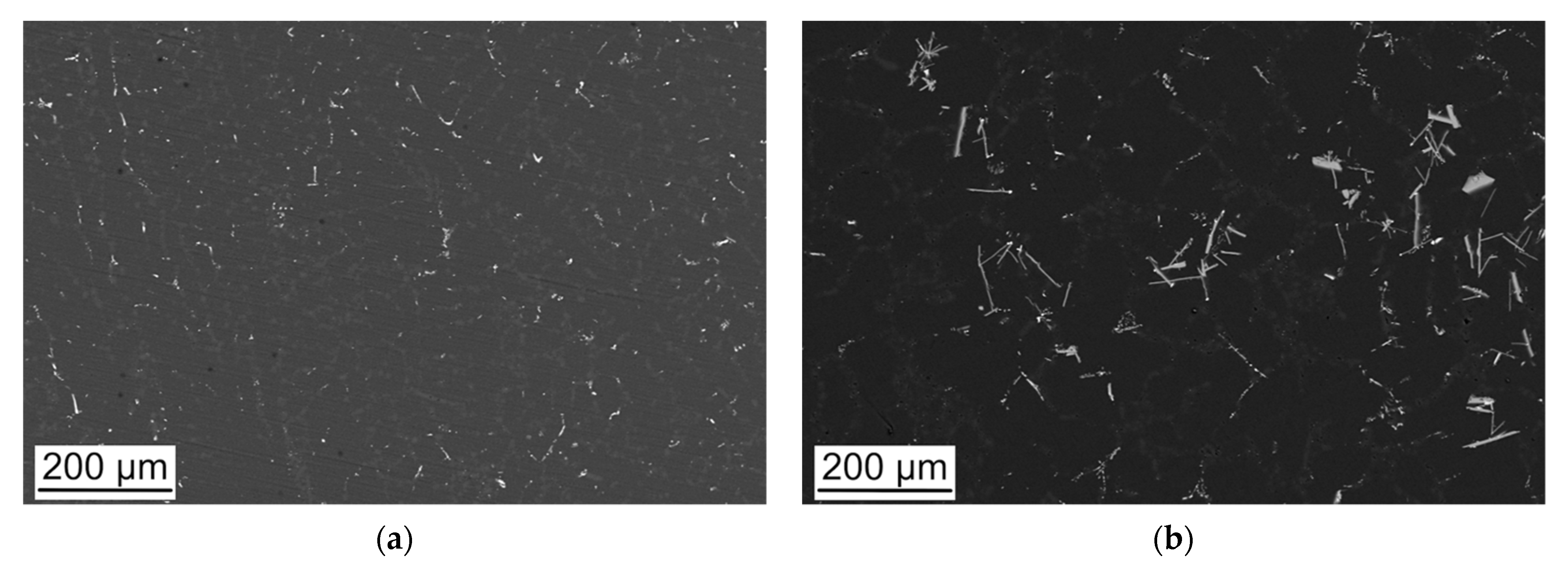
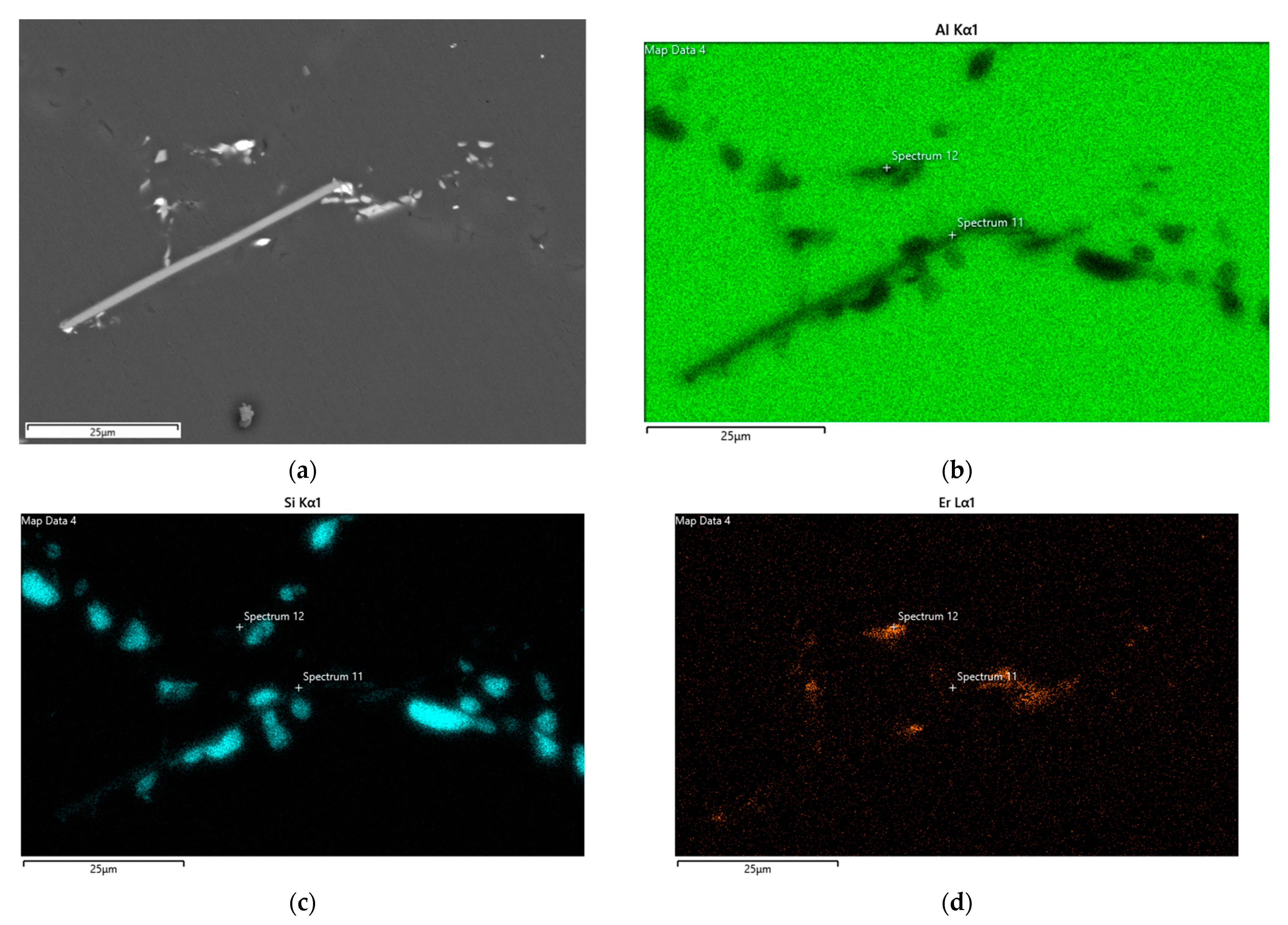
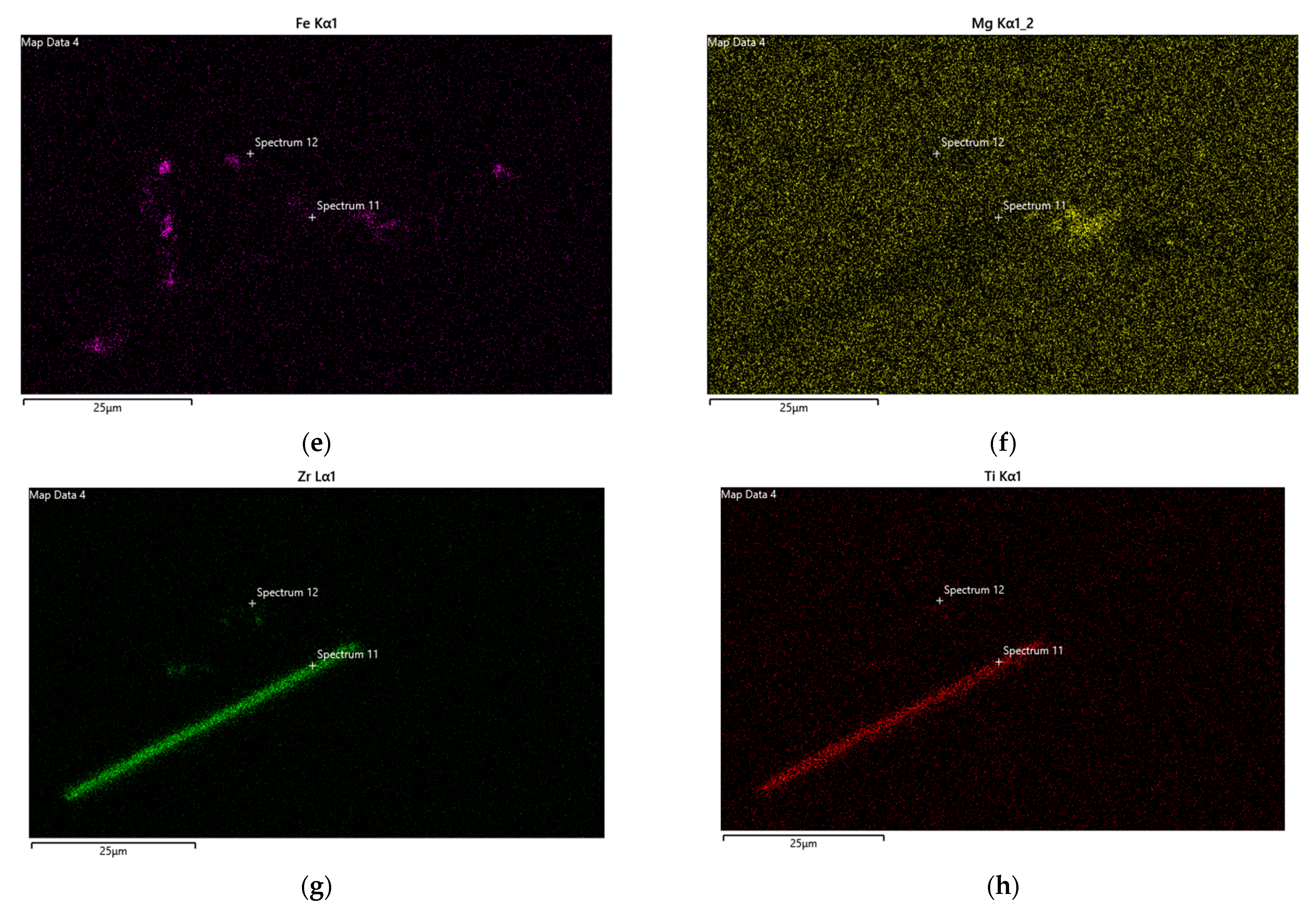
3.1. Alloy Microstructure

The microstructural features and aging behavior of the three alloys in the T6 condition will be here summarized anticipating both creep test and fractographic analyses results. The authors of the present paper have presented and discussed them in detail elsewhere [46].
The casting alloys are characterized by the dendritic grain size of 1462 ± 350 μm for A356 alloy, 1157 ± 186 μm for E3 alloy and 383 ± 98 μm for the Zr-containing alloy. Additionally, the secondary dendrite arm spacing decreased from 31.5 μm for A356 to 24.1 μm and 18.2 for E3 and EZ35, respectively. In PA conditions, the α-Al phase at the dendritic core is flanked by Si particles and by coarse phase containing Er and Zr in the modified alloys and also combinations of Fe, Cu and Mg and minor alloying additions in the reference alloy. In as-cast conditions, the eutectic Si length was longer and with higher aspect ratio for A356 (about 27 μm and 10.8, respectively), but shows a rapid decrease of both morphology parameters within the first dozen of minutes at 540 °C, reaching respectively 9.2 µm and 4.2 after 5 h at 540 °C. On the other hand, E3 and EZ35 form coral-like eutectic Si structures, resulting in shorter and lower aspect ratio Si particles in metallographic sections (of the order of 4 μm and 1.65, respectively) [46]. The 5 h SHT only slightly increased the average eutectic Si particle length, while decreasing the aspect ratio to about 1.35 for both alloys. Thus, the morphology of Si in these alloys was more related to the as-cast microstructure than to further exposure at high temperature. Further, the area fractions of coarse intermetallic phases for the A356, E3 and EZ35 alloys, which were 0.5, 0.9 and 1.3 vol% in as-cast alloys, after 5 h SHT reduced to 0.3, 0.6 and 1.1 vol% [46]. The Mg-containing π-Al8Mg3FeSi6 Chinese script and Mg2Si phases show the most significant changes during the 5 h SHT. Contrarily to the other alloys, part of the coarse intermetallics in the EZ35 alloy are located in intradendritic regions and those in interdendritic regions are of complex shape and composition.
Alpha phase strengthening in A356, E3 and EZ35 alloys, due to the presence of nanometric precipitates of Al3Er, Al3Zr and Al3(Zr,Er) is discussed in [50]. After solution heat treatment the peak hardness obtained by overaging at 200 °C reached about 97, 109 and 133 HV for A356, E3 and EZ35 alloys, respectively, in all cases with the maximum standard deviation close to 4 HV. Close hardness values are expected for the creep specimens, tested after performing the same solution treatment and aging.

3.2. Creep Tests at 300 °C

Creep tests at 300 °C, carried out at the same stress level of 30 MPa, led to the creep curves (strain vs. time plot) shown in Figure 1a. While the alloy with only Er addition displayed slightly lower times to rupture with respect to the reference A356 alloy, the one containing both Er and Zr clearly shows a longer test duration. The alternative arrangement of creep test results in terms of minimum strain rate plotted vs. time in Figure 1b better highlights differences in the initial transient stage, in the value of the minimum creep strain rate and in its increase. During the initial loading stage and during the primary stage transient, the alloys with greater addition of Er and Zr display less overall strain and lower strain rates and lower minimum creep rates. The minimum strain rate was slightly higher for the reference alloy rather than for the Er-modified alloy (0.0142 and 0.0129%/h, respectively). On the other hand, EZ35 alloy was clearly the one displaying the higher creep resistance under the testing conditions, since its minimum creep rate decreased to 0.0071%/h, that is about one half of those of the A356 and E3 alloy.
Figure 1b further shows that the time and strain range characterized by the minimum creep strain rate was limited. Rather, after reaching the minimum value, the strain rate gradually increased for the three alloys, up to a time closer to the final fracture. Despite its relatively good creep resistance in terms of the minimum creep strain rate, the E3 alloy displays a relatively rapid increase of strain rate in Figure 1b compared to the reference alloy.
Both ductility indexes show the same trend for the alloys. As matter of facts, the strain at fracture was 9.93%, 13.54% and 11.68% for the A356, E3 and EZ35 alloy, while the reductions of area were 2.68%, 22.97% and 8.72% for the alloys in the same order.

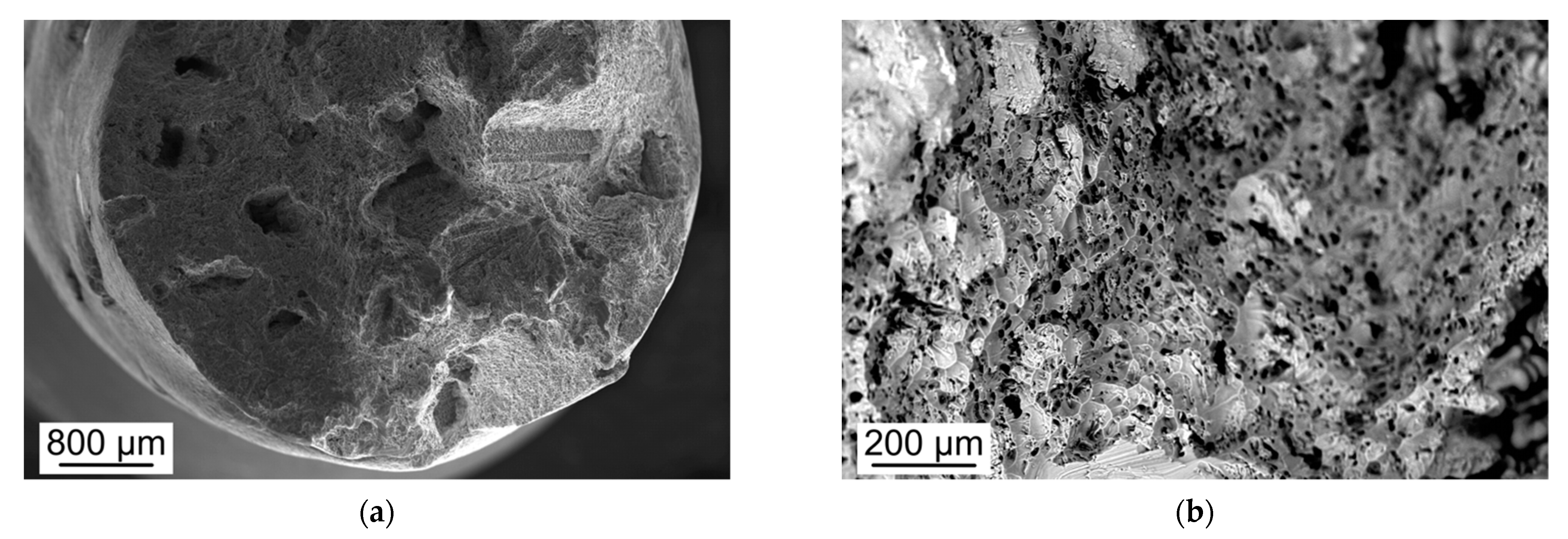
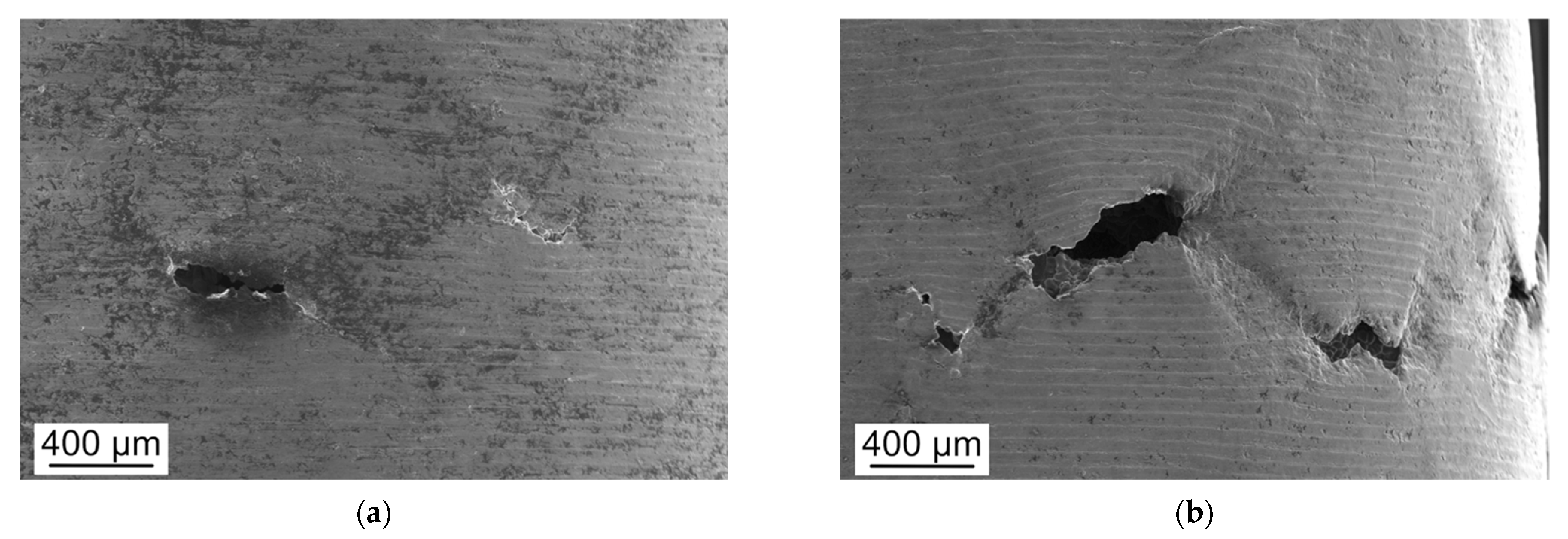
3.3. Fractographic Analyses

Representative results from fractographic analyses of crept specimens are given in Figure 2, Figure 3 and Figure 4. Figure 2a shows a low-magnification image of the fracture surface of A356 specimen. The big reliefs and depression on the specimen surface, also visible on the contour of the fracture surface, were, at least partly, associated to decohesion along dendrite grains, which were relatively large in this alloy. This agreed with the features observed on the external surface of the A356 crept sample (Figure 3a) at a few millimeters distance from the final fracture.
At a higher magnification scale (Figure 2b and Figure 4), the fracture surfaces of the three alloys were characterized by the presence of dimples, as a sign of the ductile behavior of the Al matrix, overaged after prolonged maintenance at 300 °C. In the A356 alloy dimples mainly included Si particles (Figure 2b). In the modified alloys E3 and EZ35, dimples also nucleated at Er- and/or Zr-rich coarse particles. These features can be clearly observed by comparing Figure 4a,b, taken in the same region of specimen E3 with secondary electrons and backscattered electrons (BSE), respectively. Due to their Z-contrast, Er containing particles are the brightest in BSE fractographs and micrographs.
Representative micrographs of longitudinal sections of the above specimens at the optical microscope are shown in Figure 5 and Figure 6. Specifically, Figure 5a, taken on alloy A356, confirms that the fracture path generally follows the coarse dendritic grains of the alloy, where the eutectic Si and α-Al phase are present. The higher magnification image further shows that the creep fracture surface also follows interdendritic regions, which are underlined by the presence of the grey eutectic Si phase. In this alloy, eutectic Si particles have high aspect ratio (i.e., maximum to minimum length of the particle). In correspondence to these Si particles, decohesions at the particle/matrix interface rather than their fractures are observed.
The fracture path described above for the reference A356 alloy was essentially the same observed on longitudinal sections of Er- and Zr-containing alloys, with the difference that in them higher local strains at the final fracture were suggested by secondary cracks that follow the same interdendritic path. In Figure 6, refers to alloy E3, the high strain at fracture can be noticed in the low-magnification micrograph. In the same crept specimen, some discontinuities between matrix and Er-containing coarse interdendritic particles were observed. The SEM-BSE micrograph in Figure 7 of the longitudinal section of E3 sample further shows these as bright particles, with a simple, more or less elongated shape, which tended to orient along the vertical, loading and strain direction (vertical in Figure 7). In the modified alloys E3 and EZ35, the fracture path can also include some of the intergranular porosities related to the casting process.
Even if macroscopic strains were noticed for the three alloys only close to the fracture surface, the first signs of microstructural creep damage were observed a few millimeters far from the final surface. This clearly appears on the outer surface of the crept specimens, where the fracture mechanism leading to the formation of intergranular and interdendritic fracture can be clearly observed from the presence of microcracks. Figure 3a,b depicts the ones for the A356 and EZ35 alloy, respectively. While the change of crack orientations corresponding to an interface between two dendritic grains can be observed on both alloys, grain boundary sliding is suggested by the change of levels of the horizontal turning lines only on the surface of EZ35, characterized by the finest dendritic grains (Figure 3b). Due to the small sliding extension (some tenth of μm on grains displaying it compared to the material grain size), the contribution of grain boundary sliding to the overall creep elongation is limited also for this alloy.
Figure 7 shows an EDS map of element distributions taken close to the fracture surface of the E3 specimen. The combined analysis of Al and Si once again shows that the preferred fracture path was localized along the interdendritic eutectic regions, where Si was clearly well globularized. Er-containing particles can also be identified as the bright particles in the BSE micrograph. The corresponding maps show that Er can be found in elongated interdendritic particles (reasonably combined with Al). Er is also partly combined with Mg or Fe in particles whose morphology suggests the progressive dissolution of the coarse particles with complex composition and complex morphology. Lastly, at higher magnification some extremely fine, Er-containing particles appear at the surface of eutectic silicon, at least partly related to the presence of Er in eutectic silicon in the as cast structure [50].

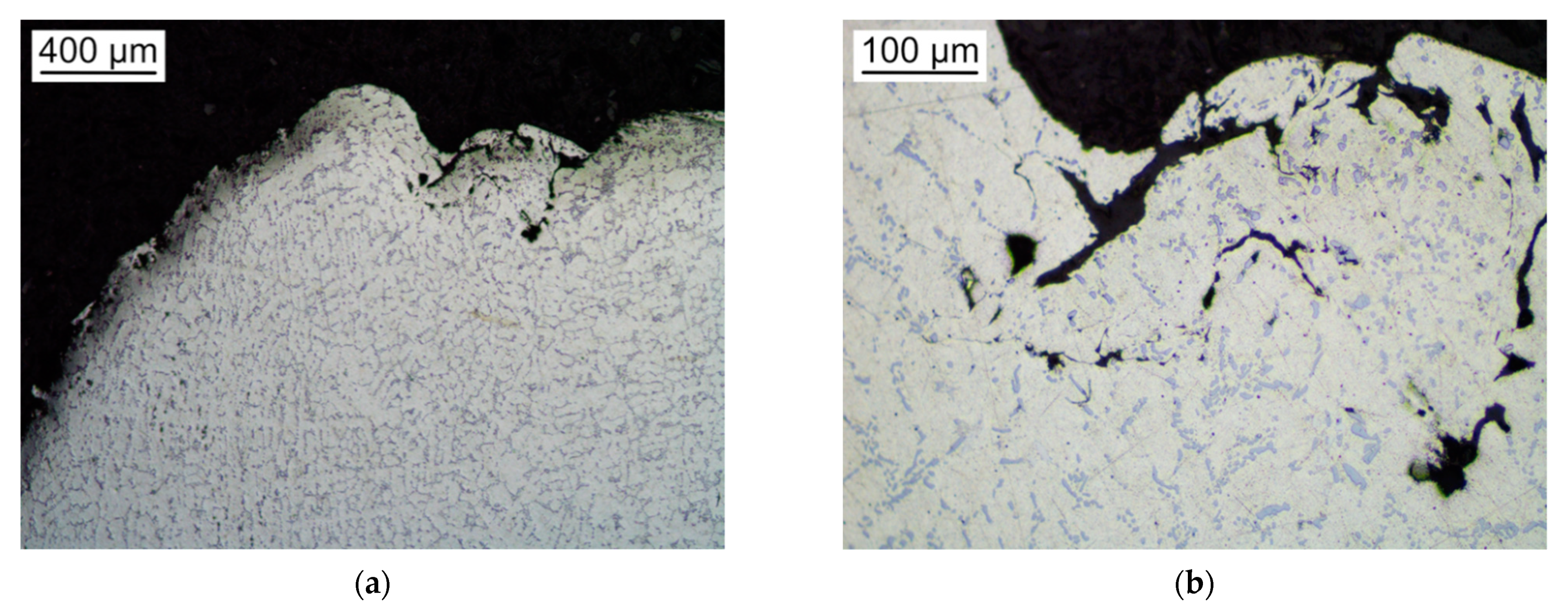
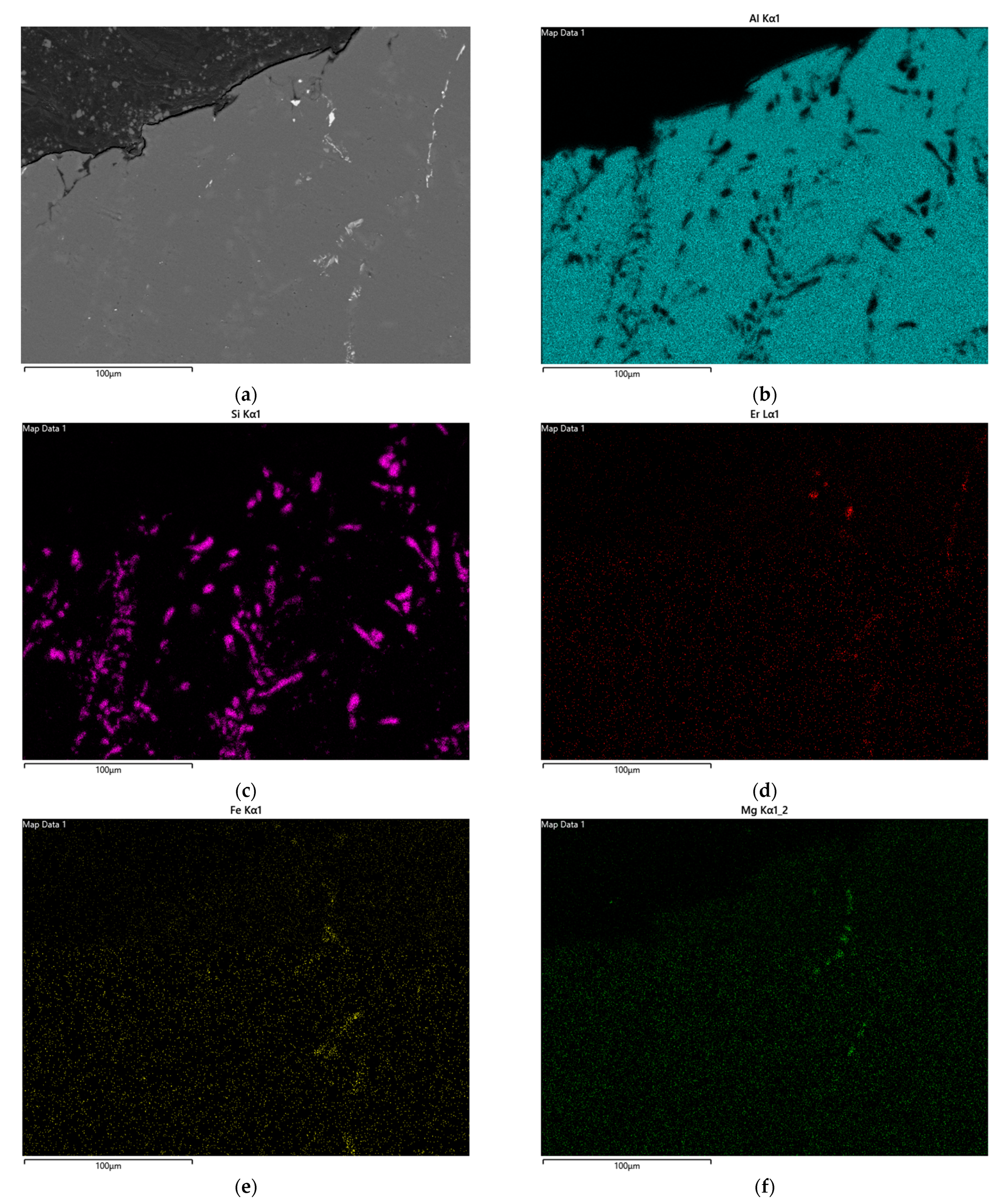
3.4. Metallographic Analyses of Specimens Aged at 300 °C

The analysis of the microstructure of samples aged for 100 h at 300 °C was mainly aimed at investigating the differences between the alloys in terms of coarse intermetallic structure. Thus, BSE images of the samples were taken and the amount of coarse intermetallics, appearing as bright particles, was measured in terms of area fraction on images (each one with an area equal to 0.196 mm2). The micrographs E3 and EZ35 alloy are shown in Figure 8. The threshold of the counting method was set so that the counting of eutectic particles, slightly visible in micrographs, was avoided. The area fraction of coarse intermetallic phases in A356, E3 and EZ35 alloys resulted as 0.16%, 0.88% and 3.02%, respectively. In A356 alloys the minor amount of intermetallics consists in Fe-containing particles, while in E3 alloys the intermetallics are of a different type, characterized by the combination of Er with Fe or Mg. These particles were generally located in interdendritic regions (Figure 8a) and corresponded to those visible on crept specimen and shown in Figure 7. The Er-containing intermetallics are observed also in the sample of the EZ35 alloy. Clearly, in this latter alloy also Zr-containing particles were identified. Most of them were elongated Zr-containing particles clearly visible in Figure 8b.
Figure 9 shows a representative element mapping for the EZ35 alloy after 100 h at 300 °C. Similar to what observed on the crept sample in the E3 alloy shown in Figure 7, Er was distributed within different groups of particles. A first group of compact and bright particles (corresponding to Spectrum 12 in element maps and to the chemical composition in Table 2) includes Er, Al and possibly some Si (a eutectic silicon particle was very close to the analyzed one). The other Er-containing sets of particles were characterized by the concurrent presence of Fe or Mg, as clearly shown by elemental maps in Figure 9. The morphology of some of these Fe- or Mg-containing particles was similar to that observed in the E3 alloy in the metallographic sample (Figure 8b) and in the gauge length of the crept specimen (Figure 7 and Figure 9) and suggests that they could be the residuals of the particles with complex composition and morphology observed also in the as-cast condition and partly modified during the solution treatment [46]. Figure 9 also includes some Zr-containing particle with the size of the order of one micron, some of which are also iron-containing. Lastly, the most characteristic particles of secondary phases in the EZ35 alloy were the elongated Zr-Ti-Al particles that can also be seen in Figure 9 (point 11 in maps, with EDS analysis results given in Table 2). These particles, to which the presence of the fine-grain structure of this alloy was attributed [46], clearly appeared in the micrograph taken at lower magnification in Figure 8, where their general intragranular location can be appreciated.

4. Discussion

The comparative creep tests performed at 300 °C under nominal stress of 30 MPa suggested that the alloy with the combined addition of Er and Zr was more promising than the other modified alloy, both in terms of an extended lifetime and of a lower minimum creep strain rate.
The creep curves of the three alloys were compared to known literature creep curves of the A356 alloy and of some alloys modified by the addition of elements (different combinations of Cu, Zr, Mo and Mn), tested under the same temperature and stress, but in tension or compression loading and with different initial temper condition [39,40,51,52]. While recently impression creep results have been reported for A356 with different Er and Zr content [53], a direct comparison with them was prevented by the use of lower testing temperature and by the use of impression creep, with no easy correlation between strain rate and applied stresses, these latter reported to be in considerably higher range.
In the case of symmetrical creep behavior, the compressive and tensile creep curves can be compared considering the absolute true stress, strain and strain rate. Further, a power law dependence between the (absolute) true strain rate (de/dt) and the (absolute) true stress σ, the former can be written as:
de/dt = f(σo) × (1 + ε)n
where n’ is the apparent exponent of the power law, ε and σo are the engineering strain and stress, respectively. In the case of tests carried out at the same temperature and the same initial engineering stress, the slope of the curve corresponds to the exponent of the creep strain rate when the true strain rate (de/dt) vs. (1 + ε) is plotted with double logarithmic axes. This kind of plot is adopted in Figure 10a,b to compare different creep curves.
The results will be discussed both in terms of the minimum strain rate, of strain rate correlation with true stress and of the strain at which creep damage occurs and develops leading to final fracture with high/low ductility indexes.
To the authors’ knowledge, a creep curve on the A356 casting alloy at 300 °C and applied stress 30 MPa is available in literature only for the compressive creep. It is reported by E. Ozbakir [52] for an initial slightly overaged condition (SHT, 12 h natural aging, further 5 h aging at 200 °C). Despite the overaged condition, the room temperature tensile properties of the alloy were slightly higher (YS 230–250 MPa and UTS 250–280 MPa) than those previously obtained by the present authors for the A356 alloy [45]. The A356 alloy tested by Ozbakir [52] is referred in Figure 10a as A356-R1, following the author’s name. It can be noticed that the slightly overaged A356-R1 alloy reached a minimum true strain roughly double than that of the present alloy.
All the other alloys tested under the same temperature and compression or tension stress level (compared in the same plot) are characterized by the addition of alloying elements with the aim of forming sets of strengthening particles (precipitates or dispersoids) in addition to those of the β-Mg2Si sequence [39,51,52]. For different datasets, the minimum strain rate tended to decrease (and strengthening effect increase) as strengthening alloying elements were added. Thus, the strengthening effect was lower for the present A356 alloy than for E3 and EZ35, for the alloy A356-R1 than A356-R2 (A356 + 0.5%Cu), for these latter than alloys MG1 and MG2 corresponding, respectively, to A356-R1 and A356-R2 with Mn, Cr and Zr additions (0.15 mass% per element). The same holds for creep compression curves under the same testing condition obtained by Farkoosh et al. [51] for Al-7Si-0.5Cu-0.3Mg (referred as MG3R) and for the same alloy with 0.3%Mo (MG3R3M alloy), tested at 300 °C after an optimized aging treatment (SHT + 5 h aging at 200 °C) and 100 h soaking at 300 °C before creep.
A second comparison between experimental and literature data available can be made for tension creep at 300 °C and 30 MPa. While for tension tests a simple comparison on the basis of the times to rupture could be performed, a more detailed analysis including creep resistance, strengthening mechanisms and creep damage and rupture considering the same axes of Figure 10a was here preferred.
The presently investigated alloys in the T6 condition are compared to those by Farkoosh [39,51] for alloys that, after SHT and aging were soaked at 300 °C for 100 h. Specifically, the alloys considered by Farkoosh in [39] were an Al-7Si-0.5Cu-0.3Mg-0.3Mo alloy (referred as MG3R3M) and its modified versions, obtained by adding Mn in 0.15–1 mass% range (the amount of which can be deduced from the number before the final M in the alloy grade name). Concerning the initial condition of different sets of alloys, it can be noticed that, in the alloys analyzed here by Farkoosh [39,51], due to the prolonged soaking anticipating creep, the strengthening effect of the less stable precipitates of the β-Mg2Si sequence, but also those of the quaternary Q-AlSiCuMg sequences, was reasonably lost as experimental data on the aging response recently presented by Pan and Breton show for 300 °C [54]. As a result, most of the creep strengthening for these alloys has to be correlated to the more stable strengthening particles formed with added elements, to atoms in solid solution into the α-Al matrix, and finally to grain size and grain boundary particles, both of them reducing grain boundary sliding and its contribution to the total strain rate. For this reason, the Al-7Si-0.5Cu-0.4Mg alloy referred as MG3R in [51] failed after a couple of hours, while creep life increased in Mo- and Mn-including alloys due to the formation of stable fine dispersoids of Al-(Fe,Mo)-Si or Al-(Fe,Mo,Mn)-Si during SHT. The creep life tended to increase up to 180 h (close to those of the presently investigated alloys) with Mo and Mn additions, at least to certain levels. On the other hand, the minimum creep rate in tension or compression of the alloys reported by Farkoosh [39,51] decreases with the amount of Mn, corresponding to the increased amount of strengthening dispersoids [37,39,51]. The minimum creep strain range of A356, E3 and EZ35 alloys is in the range of the highly alloyed grades considered by Farkoosh. The minimum creep strain rates have thus kept a certain degree of strengthening also in the A356 alloy, to which further effects adds up for the Er- and Zr-containing alloy. The other two elements are responsible for the progressive reduction of grain size, morphology change of eutectic Si and of interdendritic coarse particles and of higher amount of fine intragranular strengthening particles, thus reducing the minimum creep rate. The decrease of minimum creep strain rate with Er- and Zr- additions to the A356 alloy was also observed at the higher stress in impression creep [53].
Both in compression and in tension creep, the correlation between the true minimum strain rate and the term (1 + ε) (proportional to true stress) displays a range where a regular, almost linear, increase in strain rate occurs. The slope of the curve corresponds to the apparent Norton index (n’ in Equation (1)), which is particularly high. This situation is characteristics of creep strain in particle strengthened alloys and has been recently described also by [55] for an Al-Mg-Zr alloy and also by Spigarelli for a set of Al-alloys strengthened by nanoscale particles [56]. The presence of strengthening particles produces a threshold (or quasi-threshold) effect that in the simplest models’ versions, at constant temperature, considering engineering stress and strain can be described by the following equation
dε/dt = (σ − σth)n
In Equation (2) n is generally referred as the (true) exponent and σth as the threshold stress, which can be estimated when experimental strain rates ranging of some orders of magnitude are available [39,55,56]. In the presence of this behavior, for alloys of close composition tested under the same level of stress σ, the apparent index (n’, in Equation (1)) is lower for the alloy with lower strengthening effect [39,55]. Further, for the same material, n’ tends to decrease as the stress level increases, reaching the value of the (true) stress exponent n for the matrix at high applied stress.
These effects can be observed, at least qualitatively, in the comparison of creep curves in Figure 10a,b. Figure 10a shows that the slope for the present A356 alloy was slightly higher than that of the A356-R1 alloy, corresponding to the presence of coarser strengthening particles (precipitates). The same figure shows that the alloys characterized by the presence of (Mn + Cr + Zr or Mo) or those containing Cu, all elements forming during heat treatments fine stable intragranular particles (dispersoids or precipitates), were characterized by a relatively steep part of the curves following the minimum creep strain rate.
The same trend to display a faster increase of the strain rate with (1 + ε) for the curves characterized by the low creep rate (i.e., high creep resistance) can also be observed in Figure 10a for creep tension tests results. For most of the alloys, the part of the curve following the minimum creep rate was almost straight, with a nearly perceptible tendency to decrease before the final steep increase corresponding to creep damage progression. The presently investigated alloys, with a closer minimum strain rate to some of the Farkoosh ones, also had similar slopes for the following part of the curve. For A356, E3 and EZ35 creep curves, the n’ estimated from the above curve was high, even higher than the value close to 30 evaluated by multiple creep tensile tests at lower applied stress by Farkoosh [39] for the MG3R3M15Mg alloy for which the creep curve in Figure 10b is close to those of the E3 and A356 alloy. In the work by Rashno [53] where impression creep at 200–275 °C was performed at the very high stress levels typical of impression creep, the A356 alloys modified with higher amounts of Er and Zr the apparent stress exponent was only 6–7.
As suggested before, the high n’ values observed in the present case could be correlated to the presence of strengthening particles, and to a non-negligible threshold stress value in creep strain rate models, while the role played by grain boundary sliding in the case of fine-grained structures is not straightforward (and in any case of minor importance also for the fine-grained EZ35 alloy). Nevertheless, the extremely high n’ values observed with the present approach based on the analysis of a single specimen could be due to inaccuracy in slope calculation, since the stress range used for the n’ evaluation was small (at 5% strain the true stress increased from 30 to 31.5 MPa). Further, concurrent overaging during the creep test could have contributed to the increase of true strain rate, and thus to increase the calculated n’. When exposed to 300 °C during creep, the precipitates of the β-Mg2Si sequence are expected to reduce their total volume fraction (a reduction in the range 10–14% is foreseen by thermodynamic calculations performed by the authors using Thermo-Calc software [57]) while particle coarsening is controlled by Mg and Si diffusion (with diffusivities at 300 °C of 3.1 × 10⁻¹⁶ and 2.6 × 10⁻¹⁶ m2/s, respectively [58]). Modeled evolution of the multiphase precipitates of the Al-Mg-Si alloy showed that the volume fraction of precipitates formed after a temperature increase during aging can have a more complex evolution [59]. The formation of the fine intragranular Si-particle, as typical alloys with excess Si [60] and also observed by the authors during transmission electron microscopy analyses on A356 aged at 200 °C for 168 h [50], can reasonably occur. The changes in precipitates size and volume are in any case thought to leave minor residual strengthening effects within the first tenth of hours. The Mg and Si diffusion rates are not far from that of Er in Al (of the order 4 × 10⁻¹⁹ m2/s at 300 °C [61]) suggesting a prolonged strengthening effect due to Er-containing fine particles formed during the heat treatment cycles anticipating creep tests in the Er-modified alloy (with bimodal size distribution in T6 condition observed on the alloy of close composition [46]). On the other hand, the 5-orders of magnitude lower diffusivity of Zr in Al suggests that, correspondingly to what observed for isothermal aging of Er- and Zr-containing alloys [23,62], far longer times are needed for coarsening and structural modifications of the fine strengthening phase containing both Er and Zr observed in the alloy in the T6 condition [46].
While the possibility to apply the previous approach to estimate a threshold stress to the case of data from a single creep test on a microstructurally stable material (i.e., no coarsening nor volume change of nanometric strengthening particles) is theoretically possible, in practice this is prevented by the limited strain rate range for single tension creep test. Thus, while the presence of strengthening particles can be considered as a reasonable cause for the high slope of the curves, it cannot be proved.
Focusing now the attention on the last step of the creep curve, the one leading to the final fracture, is worthy of consideration. In compression tests (literature curves in Figure 10a), as the strain level increased above roughly 2–3%, the curves reduced their slope, due to the concurrent barreling effect, which reduced the actual true stress in some portions of the specimen. On the other hand, a different, upward, change of slope is generally noticed in tension creep curves shown in Figure 10b. This occurs at (1 + ε) corresponding to strain levels of about 4%, 6.5% and 5.5% for A356, E3 and EZ35, respectively. Above these strains, the last stage of the creep tests characterized by creep damage development takes place. In the presently investigated alloys damage is characterized by the formation of the discontinuities presented in Figure 3, Figure 5 and Figure 6. The process of damage onset and development is suggested by the creep curves in Figure 10b. Once again, the results of the present experimental tests can be discussed comparing them to those of several A356-based alloys by Farkoosh [37,39,51]. In these alloys the progressive combined addition of Mo and Mn increased the presence of coarse intermetallics, similarly to what observed for Er and Zr additions in microstructural investigations for E3 and EZ35 alloy. Farkoosh’s alloys were further characterized by high aspect ratio of intermetallics. As discussed by these authors [8,39] and noticeable by their creep curves rearranged here in Figure 10b, the alloys with high Mn and Mo contents and characterized by the low creep strain rates are also those for which the high amount of these coarse intermetallics is responsible for the onset of creep damage at low strain, and for the following rapid increase in strain rate.
Analogously, the higher overall amount of coarse intermetallic phases with Zr and Er additions and the morphology changes induced by this latter element on eutectic Si during the alloy solidification process can explain the last stage of the creep curves in the presently investigated alloys.
Thus, the A356 alloy with a softer creep and overaging structure reached both a higher minimum creep rate and a lower level of strain for creep damage onset (approximately 4%, reached at 140 h). In the last stage of the creep test, intergranular damage started at the eutectic Si, still elongated, as revealed by microstructural observations (Figure 5).
The behavior of the E3 alloy was more complex to explain. The alloy in the T6 condition reached a relatively low minimum creep strain rate. The expected coarsening kinetics of fine Er-containing fine strengthening particles, not significantly longer than for modifications of Mg- and Si-containing phases, could be responsible of a relatively fast increase for the strain rate, while a minimal contribution of grain boundary sliding cannot be excluded. The onset of tertiary creep occurs then at an accumulated strain of 6.5% and progresses slowly with strain. As a result, the ductility indexes for E3 were the highest of the investigated alloys. The delay in the onset of damage with respect to the reference alloy and the slow damage progression with strain was reasonably due to the combined presence of globularized Si and of the mostly dissolved and compact coarse intermetallics.
The most stable microstructure, EZ35 alloy, with the higher creep-resistance and the presence of the stable Zr- and Er-containing fine particles [63], after reaching the lowest minimum creep strain rate, slowly accumulates strain. The presence of globularized eutectic Si particles, even if in combination with a high amount and high aspect ratio, but mainly intragranular, intermetallics, delays at about 280 h and 5.5% total strain and the onset of creep damage, which develops intergranularly also in this alloy and which progresses relatively in a relatively fast way.
As a final remark, in the investigated Al-Si-Mg casting alloys the creep behavior was affected by the combined presence of different features induced by minor alloying elements and preliminary heat treatments, such as Si morphology, coarse intermetallics and the fine strengthening particles (overaging or forming, depending on composition and initial alloy temper). When the creep characterization was performed on these alloys in view of specific service conditions, not only the temperature, but also the stress range should be selected, whenever possible, according to foreseen service. Further, when tension stress is considered for a component, the availability of the overall tensile creep strain curve of the alloy could allow one to detect the onset of damage forms. This holds also when multiple stress steps are performed on the same tension creep specimen, since the corresponding strain rate are potentially related to the actual strain and microstructural damage. In addition, the modification of strengthening particle during the multiple stress steps could affect these results. Finally, in situations with particularly long times or high temperatures, changes in coarse precipitates and solid solution composition could also become no more negligible.

5. Conclusions

The analysis of the results of tension creep performed at 300 °C under 30 MPa stress on a A356 alloy, on its E3 and EZ35 modified versions and of the available literature data on differently modified A356 alloys can be summarized in the following points:
  • The minimum creep strain rate at 300 °C decreased from the A356 to E3 and EZ35 alloy, corresponding to the greater amount of strengthening particles;
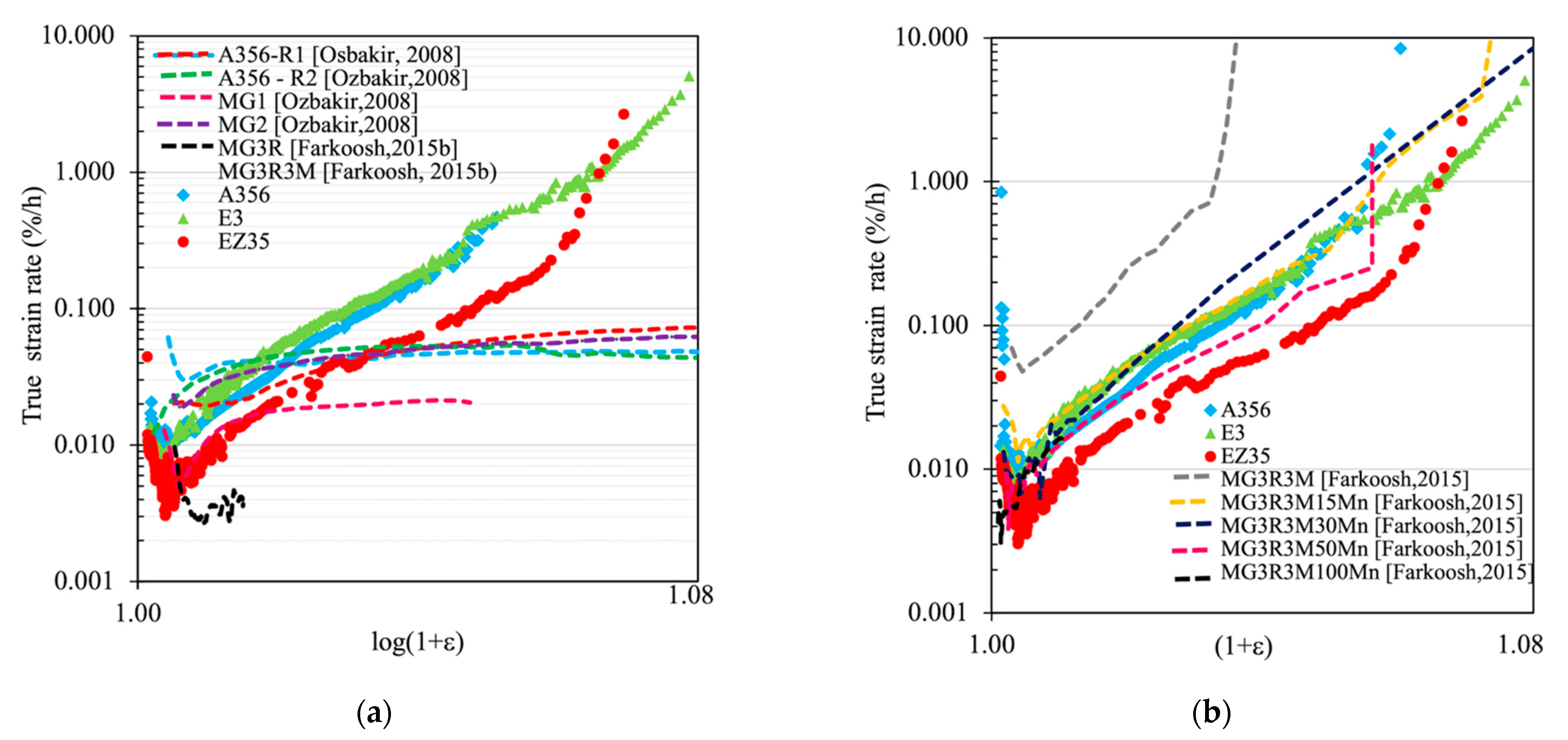
  • The analysis of creep strain rate, performed on a true strain rate vs. (1 + e) plot in order to compare creep curves in tension and in compression, shows that the strain rate increased continuously during the constant load test of about one order of magnitude due to the actual increase of true stress and to a high apparent power-law index. Comparisons with literature data confirm this behavior and correlate it to the presence of nanoscale strengthening particles that could be modeled as threshold stress-behavior;
  • The above analysis of creep strain rate for a single specimen can be carried out up to the onset of damage (in tension creep) or barreling (in compression creep). Specifically, in tension creep tests the strain level at which the onset of creep damage occurs could reduce significantly as the microstructural features related to it becoming more critical (high aspect ratio or in higher volume fractions);
  • The analysis of the overall tensile creep behavior should take into account, in addition to the minimum creep strain rate, also the final damage, causing a final increase of the strain rate up to the final fracture. As a result, the alloy EZ35, characterized by finer dendritic grains, globular eutectic Si and by high amount of stable coarse Zr-rich intermetallics, mostly in the intradendritic position, displays the onset of creep damage at about 5.5% strain and good ductility indexes.

Author Contributions

Conceptualization, E.G. and M.C.; Data curation, E.G.; Formal analysis, E.G.; Investigation, C.C. and M.C.; Methodology, E.G. and C.C.; Resources, E.G.; Visualization, C.C.; Writing—original draft, E.G.; Writing—review and editing, C.C. and M.C. All authors have read and agreed to the published version of the manuscript.

Funding

This research received no external funding.

Institutional Review Board Statement

Not applicable.

Informed Consent Statement

Not applicable.

Data Availability Statement

The raw data required to reproduce these findings cannot be shared at this time as the data also forms part of an ongoing study. The processed data required to reproduce these findings cannot be shared at this time as the data also forms part of an ongoing study.

Acknowledgments

The authors would like to thank Alessandro Morri (Department of Industrial Engineering (DIN), Alma Mater Studiorum, University of Bologna) for the production of alloys, and the master students of Politecnico di Milano, Roberto Fracassi, Hazar Safadi and Mahmoud Aly, who contributed to testing.

Conflicts of Interest

The authors declare no conflict of interest.

References

  1. Mishra, S.K.; Roy, H.; Mondal, A.K.; Dutta, K. Damage Assessment of A356 Al Alloy under Ratcheting–Creep Interaction. Metall. Mater. Trans. A 2017, 48, 2877–2884. [Google Scholar] [CrossRef]
  2. Jeong, C. High temperature mechanical properties of Al–Si–Mg–(Cu) alloys for automotive cylinder heads. Mater. Trans. 2013, 54, 588–594. [Google Scholar] [CrossRef] [Green Version]
  3. Roy, S.; Allard, L.F.; Rodriguez, A.; Watkins, T.R.; Shyam, A. Comparative Evaluation of Cast Aluminum Alloys for Automotive Cylinder Heads: Part I—Microstructure evolution. Metall. Mater. Trans. A 2016, 48, 2529–2542. [Google Scholar] [CrossRef]
  4. Caceres, C.H.; Davidson, C.J.; Griffiths, J.R.; Wang, Q.G. The effect of Mg on the microstructure and mechanical behavior of Al-Si-Mg casting alloys. Metall. Mater. Trans. A 1999, 30, 2611–2618. [Google Scholar] [CrossRef]
  5. Marioara, C.D.; Andersen, S.J.; Zandbergen, H.W.; Holmestad, R. The Influence of Alloy Composition on Precipitatesof the Al-Mg-Si System. Metall. Mater. Trans. A 2005, 36, 691–702. [Google Scholar] [CrossRef]
  6. Colombo, M.; Gariboldi, E. Prediction of the yield strength and microstructure of a cast Al-Si-Mg alloy by means of physically-based models. Metall. Ital. Int. J. Ital. Assoc. Metall. 2017, 109, 5–14. Available online: https://pdfs.semanticscholar.org/da87/55f77d332b16830fb2f28d91e0ce9c4089f4.pdf?_ga=2.137556403.2019131743.1585306164-1529008527.1567347920 (accessed on 27 April 2021).
  7. Gariboldi, E.; Lemke, J.N.; Rovatti, L.; Baer, O.; Timelli, G.; Bonollo, F. High-Temperature Behavior of High-Pressure Diecast Alloys Based on the Al-Si-Cu System: The Role Played by Chemical Composition. Metals 2015, 8, 348. [Google Scholar] [CrossRef] [Green Version]
  8. Lin, J.; Liu, K.; Chen, X.-G. Improved elevated temperature properties in Al-13%Si piston alloys by Mo addition. J. Mater. Eng. Perform. 2020, 29, 126–134. [Google Scholar] [CrossRef]
  9. Zhu, S.; Yao, J.-Y.; Sweet, L.; Easton, M.; Taylor, J.; Robinson, P.; Parson, N. Influences of Nickel and Vanadium Impurities on Microstructure of Aluminum Alloys. JOM 2013, 65, 584–592. [Google Scholar] [CrossRef]
  10. Wang, Q.; Shi, Z.; Li, H.; Lin, Y.; Li, N.; Gong, T.; Zhang, R.; Liu, H. Effects of Holmium Additions on Microstructure and Properties of A356 Aluminum Alloys. Metals 2018, 8, 849. [Google Scholar] [CrossRef] [Green Version]
  11. Baraderani, B.; Raiszadeh, R. Precipitation hardening of cast Zr-containing A356 aluminium alloy. Mater. Des. 2011, 32, 935–940. [Google Scholar] [CrossRef]
  12. Pramod, S.L.; Prasada Rao, A.K.; Murty, B.S.; Bakshi, S.R. Effect of Sc addition on the microstructure and wear properties of A356 alloy and A357-TiB2 in situ composite. Mater. Des. 2015, 78, 85–94. [Google Scholar] [CrossRef] [Green Version]
  13. Shi, Z.M.; Wang, Q.; Zhao, G.; Zhang, R.Y. Effects of erbium modification on the microstructure and mechanical properties of A356 aluminum alloys. Mater. Sci. Eng. A 2015, 626, 102–107. [Google Scholar] [CrossRef]
  14. Bevilaqua, W.L.; Stadtlander, A.R.; Froehlich, A.R.; Braga Lemos, G.V.; Reguly, A. High-temperature mechanical properties of cast Al-Si-Cu-Mg alloy by combined additions of cerium and zirconium. Mater. Res. Express 2020, 7, 026532. [Google Scholar] [CrossRef]
  15. Zamani, M.; Morini, L.; Ceschini, L.; Seifeddine, S. The role of transition metal additions on the ambient and elevated temperature properties of Al-Si alloys. Mater. Sci. Eng. A 2017, 693, 42–50. [Google Scholar] [CrossRef]
  16. Knipling, D.E.; Dunand, D.C.; Seldman, D.N. Criteria for developing castable, creep-resistant aluminium-based alloys—A review. Z. Metallkunde 2006, 97, 246–265. [Google Scholar] [CrossRef] [Green Version]
  17. Chen, S.; Liu, K.; Chen, X.G. Precipitation behavior of dispersoids and elevated-temperature properties in Al–Si–Mg foundry alloy with Mo addition. J. Mater. Res. 2019, 34, 3071–3081. [Google Scholar] [CrossRef]
  18. Morri, A.; Ceschini, L.; Messieri, S.; Cerri, E.; Toschi, S. Mo Addition to the A354 (Al–Si–Cu–Mg) Casting Alloy: Effects on Microstructure and Mechanical Properties at Room and High Temperature. Metals 2018, 8, 393. [Google Scholar] [CrossRef] [Green Version]
  19. Tocci, M.; Donnini, R.; Angella, G.; Gariboldi, E.; Pola, A. Tensile Properties of a Cast Al-Si-Mg Alloy with Reduced Si Content and Cr Addition at High Temperature. J. Mater. Eng. Perform. 2019, 28, 7097–7108. [Google Scholar] [CrossRef]
  20. Tolley, A.; Radmilovic, V.; Dahmen, U. Segregation in Al3(Sc,Zr) precipitates in Al-Sc-Zr alloys. Scr. Mater. 2005, 52, 621–625. [Google Scholar] [CrossRef]
  21. Fuller, C.B.; Seidman, D.N. Temporal evolution of the nanostructure of Al(Sc,Zr) alloys: Part II-coarsening of Al3(Sc1-xZrx) precipitates. Acta Mater. 2005, 53, 5415–5428. [Google Scholar] [CrossRef]
  22. Song, M.; Du, K.; Huang, Z.Y.; Huang, H.; Nie, Z.R.; Ye, H.Q. Deformation-induced dissolution and growth of precipitates in an Al-Mg-Er alloy during high-cycle fatigue. Acta Mater. 2014, 81, 409–419. [Google Scholar] [CrossRef]
  23. Li, H.; Bin, J.; Liu, J.; Gao, Z.; Lu, X. Precipitation evolution and coarsening resistance at 400 °C of Al microalloyed with Zr and Er. Scr. Mater. 2012, 67, 73–76. [Google Scholar] [CrossRef]
  24. Wen, S.P.; Gao, K.Y.; Huang, H.; Wang, W.; Nie, Z.R. Precipitation evolution in Al-Er-Zr alloys during aging at elevated temperature. J. Alloys Compd. 2013, 574, 92–97. [Google Scholar] [CrossRef]
  25. Booth-Morrison, C.; Dunand, D.C.; Seidman, D.N. Coarsening resistance at 400 °C of precipitation-strengthened Al–Zr–Sc–Er alloys. Acta Mater. 2011, 59, 7029–7042. [Google Scholar] [CrossRef]
  26. Kasprzak, W.; Amirkhiz, B.S.; Niewczas, M. Structure and properties of cast Al-Si Based alloy with Zr-V-Ti additions and its evaluation of high-temperature performance. J. Alloys Compd. 2014, 595, 67–79. [Google Scholar] [CrossRef]
  27. Hu, X.; Jiang, F.; Ai, F.; Yan, H. Effects of rare earth Er additions on microstructure development and mechanical properties of die-cast ADC12 aluminum alloy. J. Alloys Compd. 2012, 538, 21–27. [Google Scholar] [CrossRef]
  28. Abdelaziz, M.H.; Doty, H.W.; Valtierra, S.; Samuel, F.H. Mechanical performance of Zr-Containing 354-type Al-Si-Cu-Mg cast alloy: Role of additions and heat treatment. Adv. Mater. Sci. Eng. 2018, 18, 5715819. [Google Scholar] [CrossRef] [Green Version]
  29. Meng, F.-S.; Zhang, W.-W.; Hu, Y.; Zhang, D.-T.; Yang, C. Effect of zirconium on microstructures and mechanical properties of squeeze-cast Al-5.0Cu-0.4Mn-0.1Ti-0.1RE alloy. J. Cent. South Univ. 2017, 24, 2231–2237. [Google Scholar] [CrossRef]
  30. Colombo, M.; Gariboldi, E.; Morri, A. Influences of different Zr additions on the microstructure, room and high temperature mechanical properties of an Al-7Si-0.4Mg alloy modified with 0.25%Er. Mater. Sci. Eng. A 2018, 713, 151–160. [Google Scholar] [CrossRef]
  31. Tsai, Y.-C.; Chou, C.-Y.; Lee, S.-L.; Lin, C.-K.; Lin, J.-C.; Lim, S.W. Effect of trace La addition on the microstructures and mechanical properties of A356 (Al-7Si-0.35Mg) aluminum alloys. J. Alloys Compd. 2009, 487, 157–162. [Google Scholar] [CrossRef]
  32. Joy-Yii, S.L.; Kurniawan, D. Effect of rare earth addition on microstructure and mechanical properties of Al-Si alloys: An overview. Adv. Mater. Res. 2014, 845, 27–30. [Google Scholar] [CrossRef]
  33. Mahmoud, M.G.; Samuel, A.M.; Doty, H.W.; Valtierra, S.; Samuel, F.H. Effect of Solidification Rate and Rare Earth Metal Addition on the Microstructural Characteristics and Porosity Formation in A356 Alloy. Adv. Mater. Sci. Eng. 2017, 2017, 5086418. [Google Scholar] [CrossRef] [Green Version]
  34. Altenbach, H.; Kozhar, S.; Naumenko, K. Modelling creep damage of an aluminium-silicon eutectic alloy. Int. J. Damage Mech. 2012, 22, 683–698. [Google Scholar] [CrossRef] [Green Version]
  35. Rashno, S.; Ranjbar, K.; Reihanian, M. Impression creep characterization of cast Al-7Si-0.3 Mg alloy. Mater. Res. Express 2019, 6, 0865e6. [Google Scholar] [CrossRef]
  36. Amiresgandari, B.; Nami, B.; Shahmiri, M.; Abed, A. Effect of Mg and semi solid processing on microstructure and impression creep properties of A356 alloy. Trans. Nonferrous Met. Soc. China 2013, 23, 2518–2523. [Google Scholar] [CrossRef]
  37. Farkoosh, A.R.; Pekguleryuz, M. The effects of manganese on the Τ-phase and creep resistance in Al–Si–Cu–Mg–Ni alloys. Mater. Sci. Eng. A 2013, 582, 248–256. [Google Scholar] [CrossRef]
  38. Wang, Q.; Hess, D.; Yan, X.; Caron, F. Evaluation of a New High Temperature Casting Aluminium for cylinder head applications. In Proceedings of the 122nd Metalcasting Congress, Fort Worth, TX, USA, 3–5 April 2018; pp. 1–7. [Google Scholar]
  39. Farkoosh, A.R.; Grant Chen, X.; Pekguleryuz, M. Interaction between molybdenum and manganese to form effective dispersoids in an Al–Si–Cu–Mg alloy and their influence on creep resistance. Mater. Sci. Eng. A 2015, 627, 127–138. [Google Scholar] [CrossRef]
  40. Garat, M. Optimization of aluminium cylinder head alloy of the AlSi7Cu3Mg type reinforced by additions of peritectic elements. Inter. Met. 2011, 5, 17–24. [Google Scholar] [CrossRef]
  41. Roy, S.; Allard, L.F.; Rodriguez, A.; Porter, W.D.; Shyam, A. Comparative Evaluation of Cast Aluminum Alloys for Automotive Cylinder Heads: Part II—Mechanical and Thermal Properties. Metall. Mater. Trans. A 2017, 48, 2543–2562. [Google Scholar] [CrossRef]
  42. Javidani, M.; Larouche, D. Application of cast Al–Si alloys in internal combustion engine components. Int. Mater. Rev. 2014, 59, 132–158. [Google Scholar] [CrossRef]
  43. Roy, M.J.; Maijer, D.M.; Dancoine, L. Constitutive behaviour of as-cast A356. Mater. Sci. Eng. A 2012, 548, 195–205. [Google Scholar] [CrossRef] [Green Version]
  44. Jeong, C.Y.; Kang, C.-S.; Cho, J.-I.; Oh, I.-H.; Kim, Y.-C. Effect of microstructure on mechanical properties for A356 casting alloy. Int. J. Cast. Met. Res. 2008, 21, 193–197. [Google Scholar] [CrossRef]
  45. Colombo, M.; Gariboldi, E.; Morri, A. Er addition to Al-Si-Mg-based casting alloy: Effects on microstructure, room and high temperature mechanical properties. J. Alloys Compd. 2017, 708, 1234–1244. [Google Scholar] [CrossRef]
  46. Colombo, M.; Buzolin, R.H.; Gariboldi, E.; Rovatti, L.; Vallant, R.; Sommitsch, C. Effects of Er and Zr Additions on the As-Cast Microstructure and on the Solution-Heat-Treatment Response of Innovative Al-Si-Mg-Based Alloys. Metall. Mater. Trans. A 2020, 51, 1000–1011. [Google Scholar] [CrossRef]
  47. ISO 6892-2:2018. Metallic Materials-Tensile Testing—Part 2: Method of Test at Elevated Temperature; The International Organization for Standardization Publishing: Geneva, Switzerland, 2018. [Google Scholar]
  48. ISO 204:2018. Metallic Materials—Uniaxial Creep Testing in Tension-Method of Test; The International Organization for Standardization Publishing: Geneva, Switzerland, 2018. [Google Scholar]
  49. Rasband, W.S. ImageJ, Version 2.0.0-rc-69/1.52i, Distribution Fiji. 2018. Available online: https://imagej.net/Welcome (accessed on 29 March 2021).
  50. Colombo, M.; Albu, M.; Gariboldi, E.; Hofer, F. Microstructural changes induced by Er and Zr additions to A356 alloy investigated by thermal analyses and STEM observations. Mater. Charact. 2020, 161, 11011. [Google Scholar] [CrossRef]
  51. Farkoosh, A.R.; Chen, X.G.; Pekgureryuz, M. Dispersoid strengthening of a high temperature Al-Si-Cu-Mg alloy via Mo addition. Mater. Sci. Eng. A 2015, 620, 181–189. [Google Scholar] [CrossRef]
  52. Ozbakir, E. Development of Aluminum Alloys for Diesel-Engine Applications. Master’s Thesis, McGill University, Montréal, QC, Canada, December 2008. [Google Scholar]
  53. Rashno, S.; Reihanian, M.; Ranjbar, K. Tensile and creep properties of Al-7Si-0.3Mg alloy with Zr and Er addition. Mater. Sci. Technol. 2020, 36, 1603–1613. [Google Scholar] [CrossRef]
  54. Pan, L.; Breton, F. Evaluation of New AlSiCuMg Cast Aluminium Alloys for Automotive Cylinder Heads. In Proceedings of the 2020 AFS 124th Metalcasting Congress, Cleveland, OH, USA, 21–23 April 2020; Available online: http://afsinc.s3.amazonaws.com/2020%20Proceedings/2020-018_lm.pdf (accessed on 27 April 2021).
  55. Griffiths, S.; Croteau, J.R.; Rossell, M.D.; Erni, R.; De Luca, A.; Vo, N.Q.; Dunand, D.C.; Leinenbach, C. Coarsening- and creep resistance of precipitation-strengthened Al–Mg–Zr alloys processed by selective laser melting. Acta Mater. 2020, 188, 192–202. [Google Scholar] [CrossRef]
  56. Spigarelli, S.; Paoletti, C. A new model for the description of creep behaviour of aluminium-based composites reinforced with nanosized particles. Compos. Part A Appl. Sci. Manuf. 2018, 112, 345–355. [Google Scholar] [CrossRef]
  57. Thermo-Calc Software; Version 2020b with TCAL5.1 Al-Alloys Database; Thermo-Calc Software: Stockholm, Sweden, 2020.
  58. Du, Y.; Chang, Y.A.; Huang, B.; Gong, W.; Jin, Z.; Xu, H.; Yuan, Z.; Liu, Y.; He, Y.; Xie, F.-Y. Diffusion coefficients of some solutes in fcc and liquid Al: Critical evaluation and correlation. Mater. Sci. Eng. A 2003, 363, 140–151. [Google Scholar] [CrossRef]
  59. Du, Q.; Tang, K.; Marioara, C.D.; Andersen, S.J. Modeling over-ageing in Al-Mg-Si alloys by a multi-phase CALPHAD-coupled Kampmann-Wagner Numerical model. Acta Mater. 2017, 122, 178–186. [Google Scholar] [CrossRef] [Green Version]
  60. Chomsaeng, N.; Haruta, M.; Chairuangsri, T.; Kurata, H.; Isoda, S.; Shiojiri, M. HRTEM and ADF-STEM of precipitates at peak-ageing in cast A356 aluminium alloy. J. Alloys Compd. 2010, 496, 478–487. [Google Scholar] [CrossRef]
  61. Zhang, Y.; Gao, K.; Wen, S.; Huang, H.; Nie, Z.; Zhou, D. The study on the coarsening process and precipitation strengthening of Al3Er precipitate in Al-Er binary alloy. J. Alloys Compd. 2014, 610, 27–34. [Google Scholar] [CrossRef]
  62. Huang, H.; Wen, S.P.; Gao, K.Y.; Wang, W.; Nie, Z.R. Age hardening behavior and corresponding microstructure of dilute Al-Er-Zr alloys. Metall. Mater. Trans. A 2013, 44, 2849–2856. [Google Scholar] [CrossRef]
  63. Manente, A.; Timelli, G. Optimizing the Heat Treatment Process of Cast Aluminium Alloys. In Recent Trends in Processing and Degradation of Aluminium Alloys; Ahmad, Z., Ed.; InTech: London, UK, 2011; pp. 197–220. Available online: https://www.intechopen.com/books/recent-trends-in-processing-and-degradation-of-aluminium-alloys/optimizing-the-heat-treatment-process-of-cast-aluminium-alloys (accessed on 27 April 2021).
Figure 1. Results of creep tests carried out on the reference and modified alloys at 300 °C, 30 MPa. (a) Strain vs. time curves and (b) creep strain rate vs. time.
Metals 11 00879 g001
Figure 2. Fracture surface crept specimen in alloy A356 at low (a) and high (b) magnification, this latter taken with an electron backscattered probe to reveal the presence of phases with high Z-contrast.
Metals 11 00879 g002
Figure 3. Lateral surface of crept specimen in alloy A356 (a) and EZ35 (b).
Metals 11 00879 g003
Figure 4. Higher magnification images of fracture surface of specimen E3 taken by secondary electron probe (a) or backscattered electron probe (b), which clearly displays Er-containing phases, with higher Z-contrast.
Metals 11 00879 g004
Figure 5. Optical micrographs of longitudinal sections of crept specimens A356 alloy at low (a) and high (b) magnification.
Metals 11 00879 g005
Figure 6. Metallographic features on the longitudinal section of the crept sample E3 in optical micrograph at low- (a) and high-magnification (b) clearly displaying the eutectic regions, the material deformation in vertical direction and the presence of discontinuities.
Metals 11 00879 g006
Figure 7. SEM BSE micrograph (a) and corresponding EDS map for the alloying elements (Al (b), Si (c), Er (d), Fe (e) and Mg (f)) in the longitudinal section of E3 alloy close to its final fracture.
Metals 11 00879 g007
Figure 8. SEM BSE micrograph of E3 (a) and EZ35 (b) alloys after SHT for 5 h at 540 °C and aging for 100 h at 300 °C.
Metals 11 00879 g008
Figure 9. SEM BSE micrograph (a) and corresponding EDS map for the alloying elements (Al (b), Si (c), Er (d), Fe (e), Mg (f), Zr (g) and Ti (h)) in a sample of EZ353 alloy hold for 100 h at 300 °C.
Metals 11 00879 g009aMetals 11 00879 g009b
Figure 10. (a) Comparison between the results of the tensile creep tests performed on A356, E3 and EZ35 alloys and those reported by Ozbakir [52] and Farkoosh [51] for a A356 alloy and modified versions in microstructural conditions mentioned within the text. (b) Comparison between the results of the tensile creep tests performed on A356, E3 and EZ35 alloys and those reported by Farkoosh [39] for modified versions of the A356 alloy in microstructural conditions mentioned within the text.
Metals 11 00879 g010
Table 1. Chemical composition (mass%) of the studied alloys.
SiMgFeTiErZrAl
A3567.020.410.070.14 -bal
E37.400.340.100.120.29-bal
EZ356.660.370.110.120.310.49bal
Table 2. Chemical composition (at%) in points identified as 11 and 12 in maps of Figure 9.
Point#AlSiTiVFeZrErTotal
1175.588.194.570.090.4710.680.43100
1272.6311.87----15.49100
Publisher’s Note: MDPI stays neutral with regard to jurisdictional claims in published maps and institutional affiliations.

