1. Introduction
Materials development, including the design of new alloy formulations, has been the main driving force in the success of many of the technological advances of the last years. Increasing future demands for the development of sustainable technologies for energy production, transport, and communications require new materials with specific properties, which has led researchers to develop a new class of alloys known as high entropy alloys (HEAs). These alloys are based in a new alloying strategy, which breaks with the concepts of conventional metallurgy and emphasizes the unexplored central regions of multi-element phase diagrams. The result is an increase in the mixing entropy and solubility between elements giving way to the formation of stable and simple solid solutions breaking with Gibb’s phase rule [
1].
These new alloys appeared in 2004, as a milestone in the metallurgical field, and they have attracted the interest of researchers around the world because of the combination of properties they offer, including: high strength, fatigue and fracture resistance [
2,
3,
4], thermal stability [
5], wear resistance [
6], corrosion resistance [
7,
8], and irradiation resistance [
9]. HEAs show potential not only for structural applications but also as catalysts [
10], aerospace materials [
11], and nuclear materials [
12]. One of the most attractive aspects of HEAs is the ability to tailor the alloy composition and processing ad hoc for a given application.
The physicochemical characteristics of the present elements in the alloy will determine its structure, which is closely linked to the properties of the alloy. Depending on the composition of the alloy, the phase formed could be a solid solution, an intermetallic compound, or an amorphous phase (metallic glass). In the case of a solid solution, its crystalline structure can also be modified and will play a key role in the final properties of the alloy; for instance, HEAs with a face-centered cubic (FCC) single phase tend to be more ductile and have limited strength, while HEAs with a body-centered cubic (BCC) single phase are generally harder but more brittle [
13,
14]. Depending on the application, the optimal structure can be chosen based on a strategy to assemble different phases and achieve synergy in their properties by phase engineering since the competition between strength and ductility remains a challenge [
15].
Phase engineering can tune the structure of HEAs following two strategies: chemical tuning and physical tuning. The first refers to the chemical parameters of the elements involved as the mixing entropy (ΔS
mix), mixing enthalpy (ΔH
mix), electronegativity difference (Δχ), and atomic size difference (δ), which will determine the formation of a solid solution instead of an intermetallic or a glass material, and the valence electron concentration (VEC), which will determine the stacking character of the phase, namely, the crystalline structure of the solid solution [
16,
17,
18,
19].
The second strategy, physical tuning, considers the physical factors of the consolidation of alloys, such as the temperature or magnetic field [
20]. Several works have been published in which the empirical rules of phase formation are determined taking into account the physicochemical properties of the involved elements. However, in the microstructure and in the final properties of the HEA, the parameters used in the consolidation play an important role. Therefore, in this work, the approach followed combines the composition design as well as the processing conditions with the final aim of achieving a new alloy with an optimal balance in its mechanical properties considering the influence of each step in the processing route.
In this work, two new HEA compositions were designed applying the empirical phase formation rules published in the bibliography in order to obtain simple phases with a BCC crystalline structure as well as good mechanical properties and high temperature stability, minimizing the use of toxic elements, such as Co, as well as the weight of the alloy. Given that one of the elements susceptible to improving the properties of HEAs is Ni but which, in turn, appears as a toxic element, the influence that Ni has on both the microstructure and the final properties of the alloy was studied.
The alloys were consolidated using the powder metallurgical route, where the powders were obtained by gas atomization and processed using Spark Plasma Sintering (SPS). The main characteristic of SPS is the combination of uniaxial pressure and fast heating rates, which is generated by Joule heating provided by pulses of high intensity current [
21]. The fast generation of internal heat increases the sintering kinetics, thus, providing a minimal grain growth and a rapid densification if a proper final temperature is selected.
The rapid densification was the main reason to choose this processing technique because it avoids the segregation of elements—one of the drawbacks in the processing of HEA by casting, which is the most common processing route used in the manufacturing of HEAs [
22]. The mechanical properties were evaluated using compression tests and nanoindentation tests performed at room temperature and 400 °C, and the results are discussed in relation to the microstructural study.
2. Materials and Methods
The alloy compositions were designed considering the empirical rules published in the bibliography. The thermodynamic properties used to design the compositions were calculated using Equations (1)–(5) for the five chemical parameters of the elements involved:
where
R is the gas constant and
is the mole percent of the
ith component.
where
and
are the atomic percentages of the
ith or
jth component and
is the mixing enthalpy of the binary liquid alloy.
where
is the atomic percentage and
is the Pauling electronegativity for the
ith element.
where
is the atomic percentage and
is the atomic radius of the
ith element.
where
is the atomic percentage of the
ith element and
is the VEC of the
ith element.
The choice of elements in the alloy was made on the basis of minimizing the use of critical metals as well as the final weight of the alloy. Their stoichiometry was adjusted taking into account the ranges of the thermodynamic properties suitable for obtaining a solid solution with a BCC crystalline structure according to the empirical data found in the bibliography: 0 ≤ δ ≤ 13 (%); −22 ≤ ΔH
mix ≤ 7 (kJ/mol); 10 ≤ ΔS
mix ≤ 19.5 (J/K·mol) and VEC < 6.87 [
16,
17,
18,
19]. The resulting compositions and their physicochemical properties are summarized in
Table 1.
The designed compositions were processed by powder metallurgy. Prealloyed Fe1.5Cr1Al0.75Mo0.1Ti0.1 (A5) and Fe1.5Cr1Al0.75Mo0.1Ti0.1Ni0.25 (A6) powders were obtained by gas atomization. High purity (99.99 wt.%) Al, Fe, Cr, Ti, Mo, and Ni metals were inductively melted and subsequently atomized by compressed argon with an outlet pressure of 41 ± 1.7 bar under an Ar atmosphere.
The characterization of the atomized powders included oxygen content analysis by the inert gas fusion technique (LECO, St Joseph, MI, USA), density measurement by He pycnometry (AccuPyc 1330 by Micromeritics, Norcross, GA, USA), morphology and composition studies by scanning electron microscopy (SEM (FEI Teneo FEG-SEM, Hilsboro, OR, USA), and phase identification by X-ray Diffraction (XRD) (Siemens D5000 diffractometer by Siemens, München, Germany) in a Phillips equipment X’Pert-MPD.
Atomized powders were consolidated by Field Assisted Sintering Technology/Spark Plasma Sintering (FAST/SPS, FCT-HPD5, FCT System GmbH, TH, Germany) under reduced pressure (~4 mbar) during the whole thermal cycle. The temperature was controlled using a pyrometer that was focused on the surface of a drilled punch at only 5 mm from the powder. To protect the tool and to facilitate the electrical and thermal transfer, an additional graphite foil was placed between the powder and the graphite punches. The atomized powders were added to a graphite die of 20 mm diameter and sintered at 1150 °C at two different heating rates, 100 K/min and 200 K/min. After the densification process, the surfaces of the samples were ground to eliminate the remaining graphite.
The microstructural characterization of the SPSed samples was performed by SEM, and the chemical composition was determined using EDS compositional maps (FEI Teneo). A FIB FEG-SEM dual beam microscope coupled to EDX and electron backscatter diffraction (EBSD) detectors (Zeiss Crossbeam 1540) was used for the EBSD mapping of cross sections with respect to the compaction direction, using a step size of 100 nm with a tolerance angle of 10° to determine the grain size distribution. Phase identification was performed by X-ray Diffraction (XRD) in a Phillips equipment X’Pert-MPD, and the data were processed using the X’Pert Highscore software (version 2.2.5, Malvern Panalytical, Amsterdam, Netherlands). The microstructural characterization was completed with observation of the samples by Transmission Electron Microscopy (TEM, Jeol Jem 2000FX and FEI Talos F200X operated at 200 kV, (Thermo Fisher Scientific, Hillsboro, OR, USA).
Nanoindentation tests were performed using a Hysitron TI950 triboindenter (Bruker, Minneapolis, MN, USA) equipped with a Berkovich-shaped diamond tip, whose area function was calibrated using multiple indents on a standard fused silica sample. At least 10 indents per sample were performed, up to a maximum load of 12 mN, using loading-holding-unloading times of 5-2-5 s. For high temperature nanoindentation testing, a hot stage (Hysitron xSol, Bruker, Minneapolis, MN, USA) and a Berkovich diamond indenter fitted to a special long insulating shaft were used.
In this configuration, the sample is placed between two resistive heating elements in order to eliminate temperature gradients across the sample thickness. Dry air and argon around the tip and sample surface were used to purge the testing area to prevent heated gases reaching the transducer and reduce possible oxidation. Once the sample reached the selected temperature of 400 °C and the temperature was stable to within ±0.1 °C, the tip was placed 100 µm from the sample surface for 15–20 min to ensure passive heating of the tip before the start of the test and to minimize thermal drift. The hardness and modulus values were determined using the Oliver and Pharr method [
23].
Quasi-static compression tests were conducted using a servo-hydraulic testing machine INSTRON 8516 100 kN (INSTRON test systems, HYC, England) under displacement control. In all the experiments, the axial engineering strain in the specimen was calculated relying on the data provided by a LVDT Deflection Sensor mounted directly on the surface of the compression platens. The contact interfaces of the samples were lubricated using molybdenum disulfide grease. The experiments were conducted at a nominal (initial) strain rate of at room temperature.
3. Results
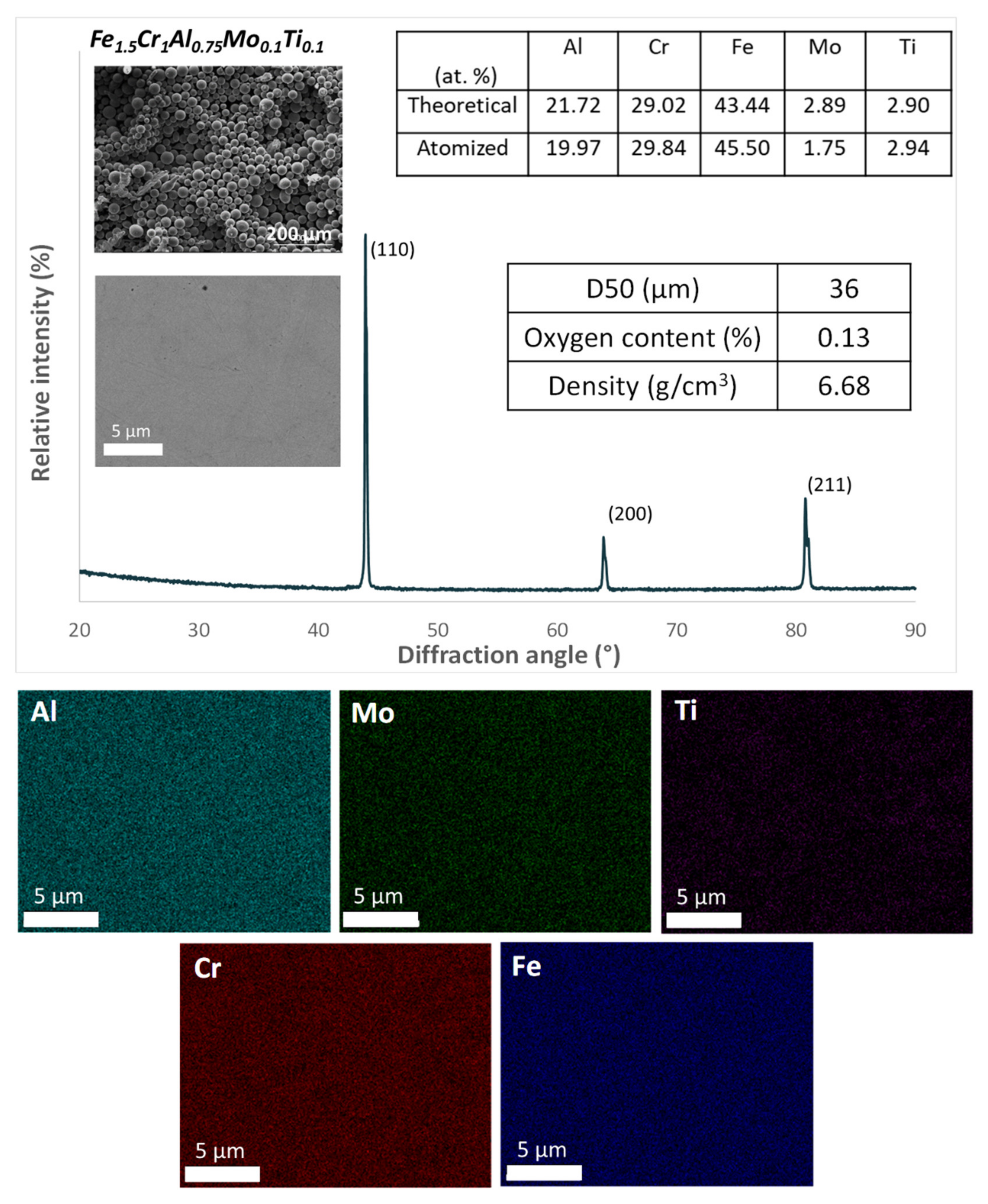
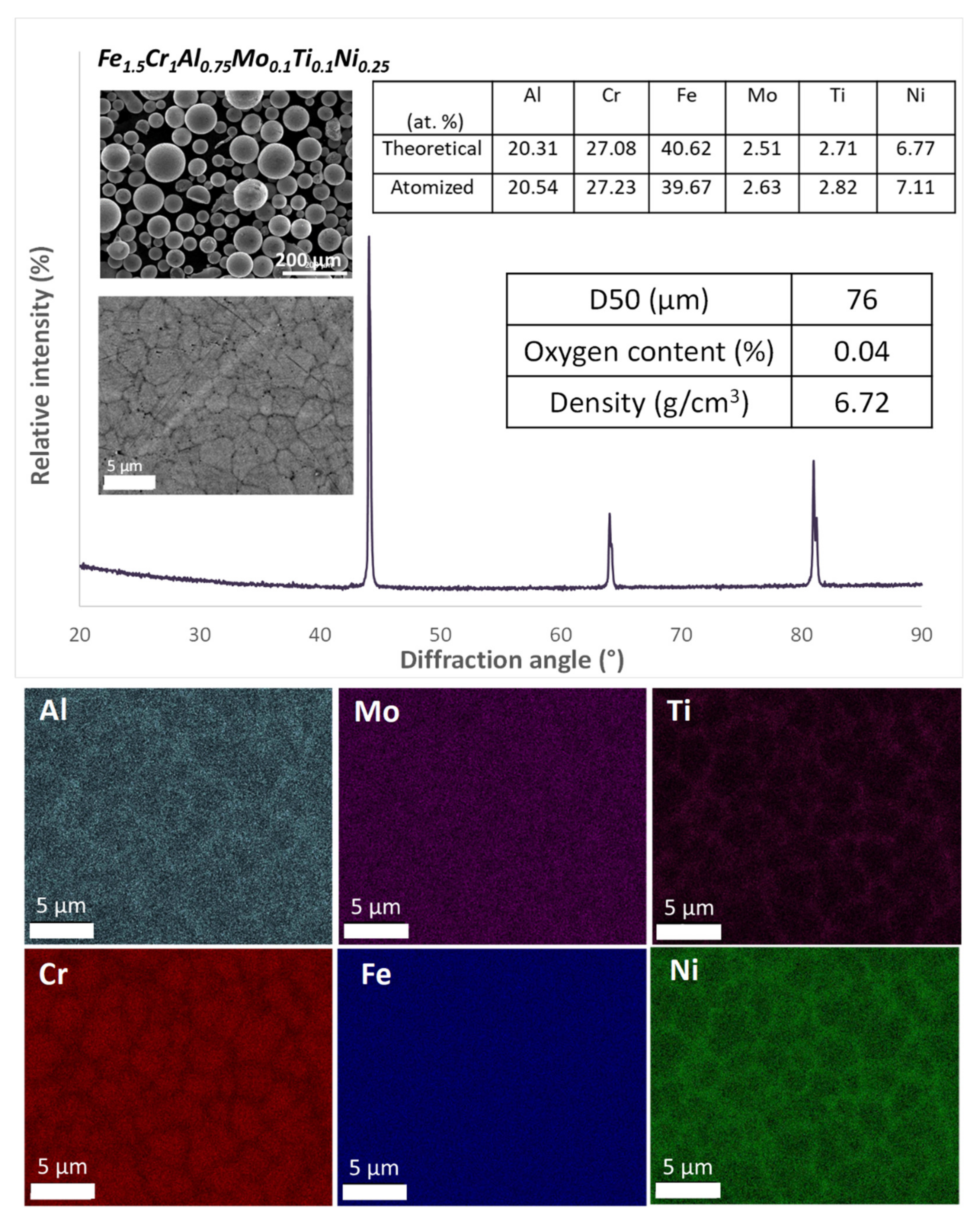
The main characteristics of the atomized powders used as raw materials are summarized in
Figure 1 and
Figure 2. Characterization of the powders revealed particles with a spherical morphology and with a chemical composition similar to the theoretical one with a low oxygen content. XRD spectra revealed the presence of a single phase with a BCC crystalline structure in both powder compositions. However, surface analysis of the composition of A6 particles showed the segregation of Ni, Al, and Ti to the grain boundaries, while compositional analysis of the A5 showed a homogeneous distribution of the elements.
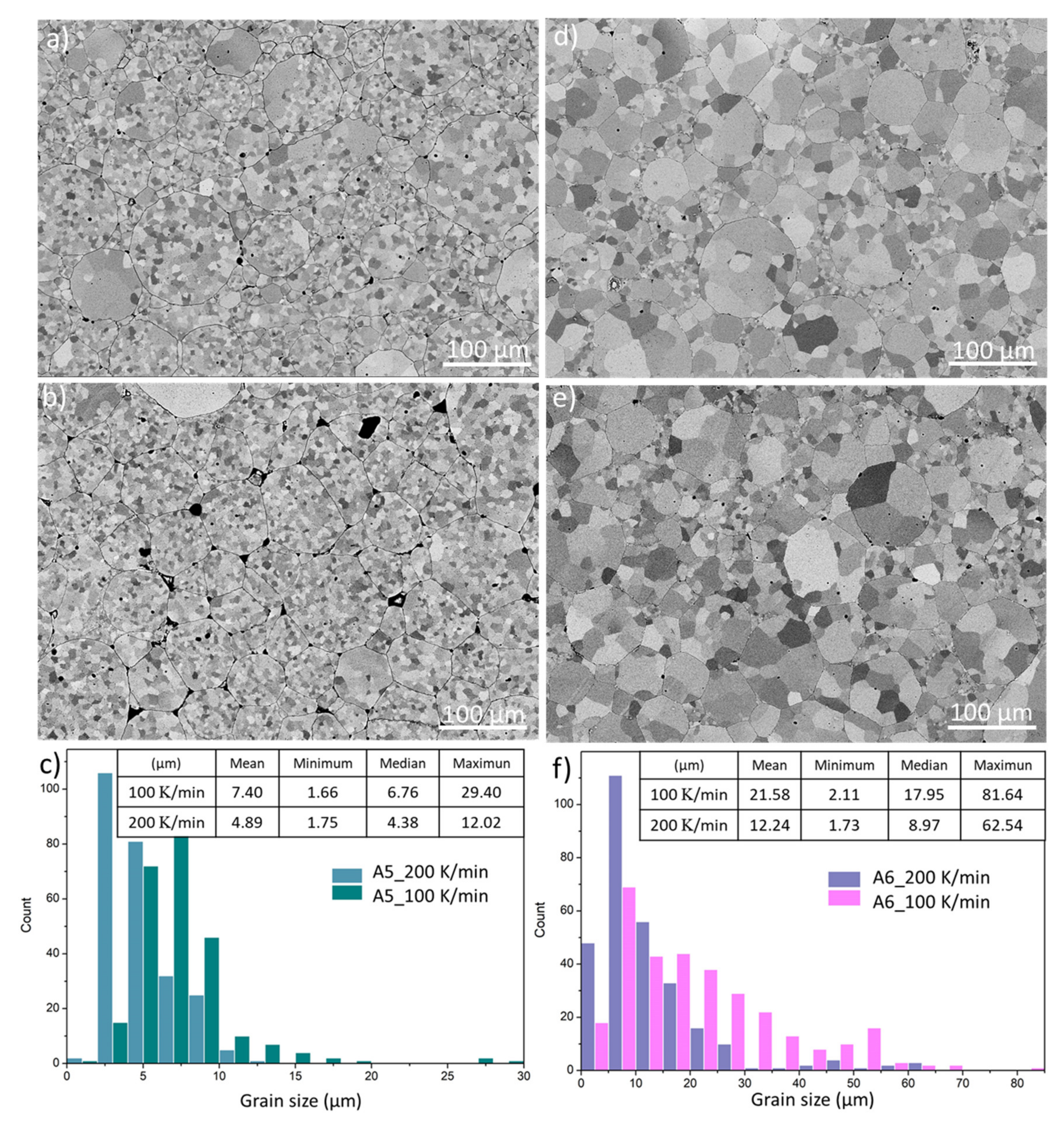
A5 and A6 atomized powders were consolidated by SPS, and the resulting microstructures are shown in
Figure 3. Taking the density of the atomized powders as the theoretical density, the relative densities of the A5 SPS samples at 100 and 200 K/min were 98% and 96%, respectively. The lower density of the sample sintered at a higher heating rate is also reflected in the porosity observed in its microstructure in
Figure 3b.
In addition, sintering at a higher heating rate also limits the grain growth as reflected in the grain size distribution of the alloy sintered at two heating rates as shown in
Figure 3c–e with the microstructures of A6 SPS samples at 100 and 200 K/min in which a higher densification is observed with very low porosity corresponding to their high relative density values (99%). As in the A5 alloy samples, a lower grain growth in the A6 alloy sintered at a higher heating rate is also observed, as evidenced in
Figure 3f. Note that the grain size distribution of these sintered samples is shifted to larger grain sizes compared with for the A5 samples because the raw atomized powder had a higher particle size distribution.
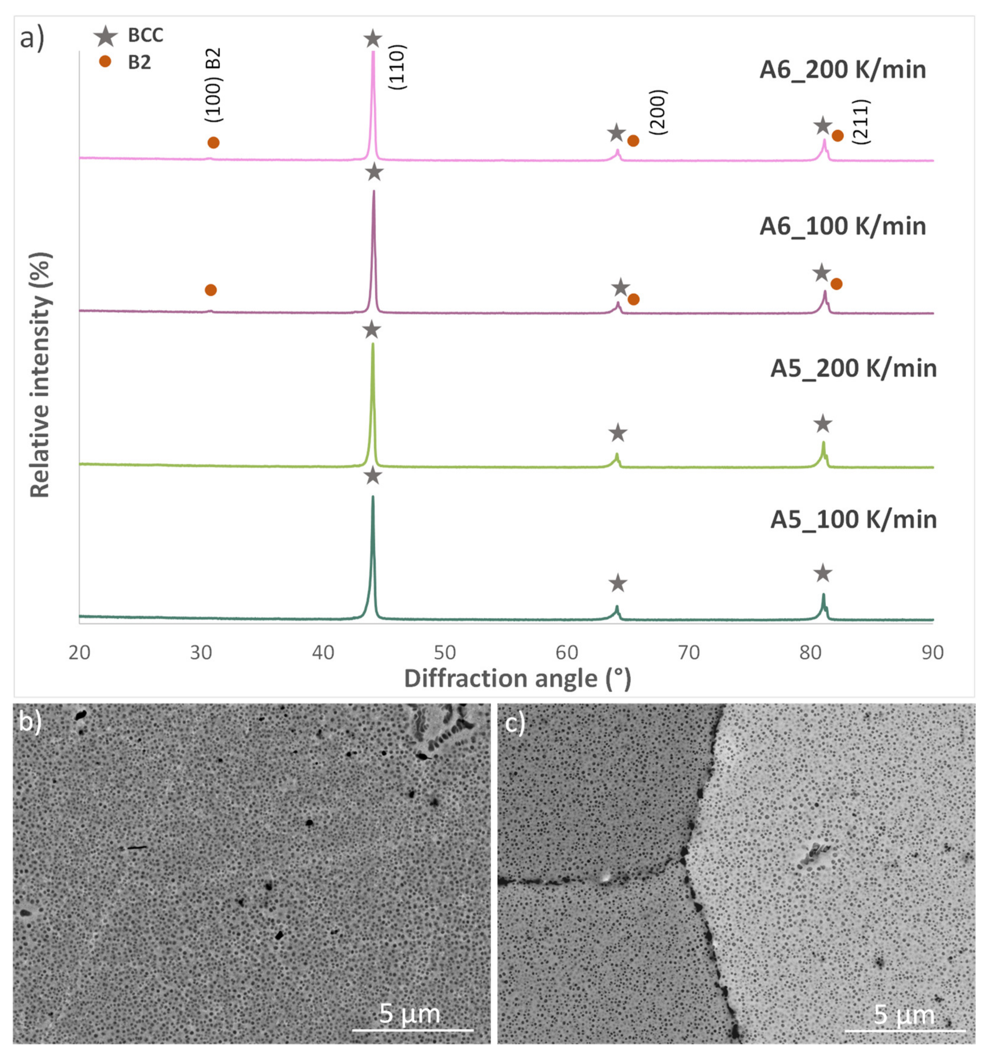
Taking a closer look at the microstructure of the A6 sintered samples in
Figure 4b,c, rounded precipitates are found uniformly distributed within the matrix. The XRD spectra (see
Figure 4a) revealed that all the samples have a BCC crystalline structure complying with the targeted structure fixed in the design of the compositions. The diffractograms of the A6 alloy also show the formation of a B2-type ordered phase independently of the heating rate applied during sintering.
The calculation of the lattice misfit between these phases BCC/B2 reveals low values for both samples: ε = 0.05% and 0.09% for the samples sintered at 100 and 200 K/min, respectively. These small values of lattice misfit are in agreement with the presence of rounded precipitates, which would be cuboidal for a moderate misfit and weave-like (from spinodal decomposition) for a higher misfit as was observed in a previous work [
24].
The TEM images and EDX compositional analysis of A6 (
Figure 5a–d) revealed that the rounded precipitates with a size of ~100 nm contain Ni, Al, and Ti, exhibiting an ordered BCC (B2) phase, while the disordered BCC-type matrix phase is richer in Fe, Cr, and Mo. The coherency of the precipitates is reflected in the TEM diffraction pattern shown in
Figure 5d. A coherent precipitation occurs with a specific crystalline orientation relationship to the matrix in which the precipitates and the matrix share a specific atomic plane in such a way that the mismatch between them is minimized.
In this diffraction pattern, the orange circles indicate the diffraction spots shared by both the disordered BCC matrix and the ordered B2 precipitates, while the blue circles indicate the superlattice reflections corresponding to the ordered B2 structure (in a B2 ordered structure with a different central atom, the BCC forbidden reflections can give way to superlattice reflections).
This BCC microstructure with coherent B2 precipitates has been observed in other HEAs containing Al and Ni [
25,
26,
27,
28], because the enthalpy formation of the binary Al-Ni is more negative and favors the formation of an Al-Ni intermetallic. The phase stability in alloys is governed by changes in the Gibbs free energy, given by:
In HEAs, the solid solution phase is stabilized by the high configurational entropy resulting from the large number of main elements in the alloy with negligible enthalpy. A more negative formation enthalpy makes the system deviate from the formation of an ideal solid solution and favors the formation of intermetallic compounds [
29].
Table 2 shows the enthalpy of formation of the binary systems of the A6 alloy; this table reflects the more negative values for the Al-Ni, Al-Ti, and Ni-Ti binaries, justifying the formation of the ordered (Al, Ni, and Ti) B2 phase in the A6 sintered samples and the segregation of these elements in the powder particles as shown in
Figure 2.
The presence of Ni in the HEA composition gives way to clear differences in the microstructure of the sintered A5 and A6 samples. As observed in the TEM images in
Figure 5, the presence of Ni in the A6 alloy favors the phase separation during the consolidation of the atomized powders. The formation of B2 rounded precipitates during A6 sintering causes the appearance of dislocations loops around them. On the contrary, the sintered A5 alloy shows a more homogeneous single-phase BCC microstructure. Some isolated precipitates, rich in Mo and Ti (as measured by TEM-EDX), were also found as indicated by arrows in
Figure 5f. However, the extent of second-phase precipitation was much lower than in the case of the Ni-containing FeCrAlMoTiNi alloy.
The microstructural differences in the two compositions together with the different grain sizes obtained by applying different heating rates during the sintering of the alloys will have a clear influence on the mechanical properties of the alloys.
Figure 6 presents the engineering strain–stress curves of the A5 and A6 alloys sintered at different heating rates. Regarding the influence of the heating rate, an increase in the heating rate improved the mechanical behavior of both alloys.
The A5 alloy sintered at 200 K/min, which showed a lower density and higher percentage of porosity, had a higher compressive strength, fracture strain, elastic modulus, and yield strength than the alloy sintered at 100 K/min due to the refinement in the grain size with the increasing heating rate. A6 samples showed higher compressive strength and fracture strain compared with the alloys without Ni in their composition. The mechanical properties of the A6 alloy were increased by the increase in the heating rate.
The mechanical characterization of the alloys was completed by nanoindentation tests at RT and 400 °C.
Figure 7 shows the hardness and reduced modulus values at RT and 400 °C for the A5 and A6 alloys sintered at 100 K/min. Both alloys present similar hardness values, with A6 being slightly harder, while exhibiting a lower elastic modulus (135 GPa) than the A5 alloy (144 GPa). The hot hardness measured at 400 °C (6.1 GPa) for FeCrAlMoTi decreases by H10% with respect to the hardness value measured at RT (6.8 GPa), while the hardness drop for the A6 alloy is less pronounced than only H6% when heating from RT (6.9 GPa) to 400 °C (6.5 GPa).
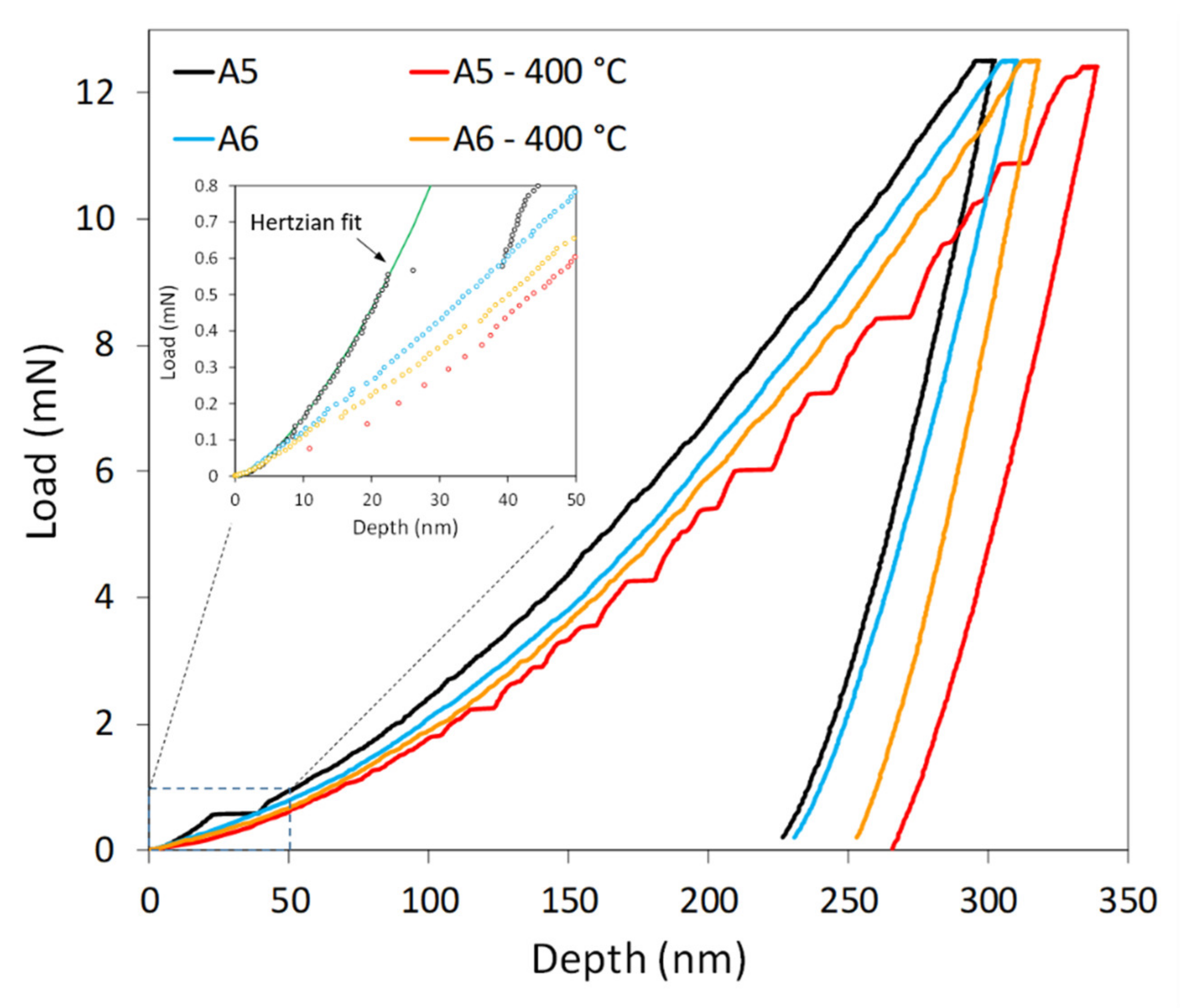
Figure 8 shows representative load–displacement curves obtained during nanoindentation tests performed at RT and 400 °C for both A5 and A6 alloys. It can be seen that, compared to the RT condition, the tip penetrates deeper into the sample during nanoindentation at 400 °C, but not by a large amount. The slight softening of the samples with an increase in the temperature is likely due to the promoted thermal activation of the dislocation glide during deformation. The hardness measured after cooling increased from 6.8 to 7.2 GPa, which could be due to “hardening by annealing” where some degree of phase separation or nanophase precipitation took place as has been reported in nanocrystalline materials [
30] and in HEAs [
31].
With increasing temperature, the modulus for A6 increases. This behavior can be attributed to the effect of the BCC phase in the sample at 400 °C, which has been observed in similar alloys [
32], where it was speculated that an increase in temperature favors the segregation of elements to form small precipitates leading to an increase in the modulus. On the other hand, the modulus for A5 decreased at 400 °C. For both alloys, the modulus determined at RT after cooling was higher (148 GPa) than before the high temperature indentation tests, indicating that microstructural changes and/or some degree of elemental segregation leading to precipitation occurred.
The nanoindentation results mainly represent the mechanical behavior of a single grain, since the size of the plastically deformed zone around the indent was small compared to the grain size of the sample, and no effect of the heating rate was observed in the nanoindentation results.
The nanoindentation curves of the alloy A5 obtained at 400 °C present displacement bursts or serrations. Serrated flow can occur during the dynamic strain aging (DSA) of a material while undergoing a mechanical test and is affected by the temperature and strain rate. Similar serrations have also been observed in BCC AlCoCrFeNi [
31]. The serration mechanism in DSA of HEA reported in the literature [
32,
33,
34,
35,
36,
37,
38,
39] is due to solute-dislocation interactions, following a pinning–unpinning process in which the dislocation is pinned by a solute atom until a critical stress is reached and the dislocation has enough energy to break free and continue until pinned again by other solute atoms, thus, causing a drop in the stress.
In a load control nanoindentation test, these stress drops appeared as displacement bursts or serrations in the load displacement curves, forming a “staircase” loading curve of A5 at 400 °C shown in
Figure 8. At 400 °C, the frequency of solute-dislocation interactions was more abundant than DSA in conventional alloys due to the large diversity of elements present in the solid solution, leading to increasingly jerky fluctuations of serrations. At 400 °C, the mobility of diffusing solid atoms was higher, and therefore, they were able to lock dislocations more efficiently.
Serration phenomena were not observed at RT where the solute diffusion rates are too sluggish to compete with dislocation velocities and only some fluctuation in the loading curve can be inferred, indicating that serration is thermally activated as it appears clearly at 400 °C, when more dislocations can be activated during deformation. The serrations observed in the A5 alloy at 400 °C are of varying magnitude and appear at random intervals. They are more numerous and larger at higher penetration depths as the loading rates decrease. At lower speeds, there is more time for the solute atoms to pin dislocations.
The load–displacement curves for A6 are smoother and more continuous than for A5, even though some fluctuations can be observed, particularly at 400 °C. In the case of HEAs, any atom of the solid solution could act as a solute, but there are certain atoms that are more capable of locking dislocations; previous investigations have revealed that Al atoms have a higher capability than other elements to pin the dislocation motion [
40,
41,
42].
In the A5 alloy, the responsible solute for the serrated flow could also be Al, and this could explain the different behavior found in the nanoindentation curves of the alloy A6, which do not show this serrated behavior. In this alloy, the Al atoms precipitated, forming the ordered B2 phase and were no longer solute atoms in the BCC solid solution, damping the serration flow of the stress. Therefore, for A6, there were no clear serrations due to the lack of dislocation pinning sources.
The magnified inset of
Figure 8 shows that in the load–displacement curve for A5 at RT. A displacement burst or “pop-in” event can be observed at a load of H 55 µN, indicating a clear deviation from Hertzian behavior [
43]. This “pop-in” was observed in most of the load–displacement curves for A5 at RT and corresponds to the elastic to plastic transition, when the maximum shear stress underneath the indenter exceeds a critical value. This pop-in is usually related to the nucleation of dislocations underneath the sample surface or, to a lesser extent, to the activation of dislocation sources.
Fewer dislocations were observed in the A5 alloy, and the plasticity onset is likely due to the homogeneous nucleation of dislocations, as the indented volume (∝ a
3, where a is the contact radius) during plastic yielding is smaller in comparison to the mean dislocation spacing “d” in the region (a < d) [
44]. In the A6 case, more dislocations are present, so that d < a, and nucleation is dominated by the mobilization and/or multiplication of pre-existent dislocation sources (i.e., Frank–Read loops).


 ,
, 


