Abstract
Modern arc processes, such as the modified spray arc (Mod. SA), have been developed for gas metal arc welding of high-strength structural steels with which even narrow weld seams can be welded. High-strength joints are subjected to increasingly stringent requirements in terms of welding processing and the resulting component performance. In the present work, this challenge is to be met by clarifying the influences on hydrogen-assisted cracking (HAC) in a high-strength structural steel S960QL. Adapted samples analogous to the self-restraint TEKKEN test are used and analyzed with respect to crack formation, microstructure, diffusible hydrogen concentration and residual stresses. The variation of the seam opening angle of the test seams is between 30° and 60°. To prevent HAC, the effectiveness of a dehydrogenation heat treatment (DHT) from the welding heat is investigated. As a result, the weld metals produced at reduced weld opening angle show slightly higher hydrogen concentrations on average. In addition, increased micro- as well as macro-crack formation can be observed on these weld metal samples. On all samples without DHT, cracks in the root notch occur due to HAC, which can be prevented by DHT immediately after welding.
1. Introduction
Lightweight design in steel constructions require an increasing use of high-strength structural steels with yield strengths ≥ 690 MPa [1,2]. These steels are mainly used in building, plant and crane construction. Their use is currently being extended to the offshore sector [3]. The joining of these steel grades by welding is mainly carried out by gas metal arc welding (GMAW). For this purpose, steel manufacturers offer numerous base materials and welding consumables with low alloying contents. Base materials with yield strengths of up to 1300 MPa [4] and filler materials of up to 930 MPa [5] are commercially available. Further developments are being driven forward, especially for metal-cored wires [6]. During welding, adequate heat control (heat input, preheat and interpass temperature) is essential to achieve the required mechanical properties in the welded joint. In case of inappropriate welding processing a local crack-critical microstructure with high hardness, locally increased stresses or strains and locally increased diffusible hydrogen concentrations can cause hydrogen-assisted cracking (HAC) in the heat-affected zone (HAZ) or in the weld metal [7]. The fundamental mechanisms of hydrogen embrittlement are extensively reported by Lynch [8] and Djukic et al. [9]. In general, diffusible hydrogen can cause a degradation of the mechanical properties, which in combination with high residual stresses or strains can lead to damage of components.
In principle, the diffusible hydrogen concentration in welded joints depends on the welding process parameters and the type of the used filler material. There are several studies that address hydrogen uptake during welding [10,11,12,13,14]. The studies show that a reduction of the diffusible hydrogen concentration in the weld metal and thus a reduction of the risk against HAC is possible through a suitable choice of welding process parameters such as arc voltage, welding current or contact-tube-to-work distance (CTWD). However, attention must also be paid to the fact that higher diffusible hydrogen concentrations are present when flux cored wires are used compared with solid wires [11,15]. In the applicable guidelines for welding high-strength structural steels [16,17], a suitable choice of preheat and interpass temperatures is recommended to minimize the risk against HAC. However, these inhomogeneous heat inputs can lead to increased welding residual stresses in the welded joint [18,19,20]. This option should rather be used to adjust the required t8/5-cooling times and thus, the microstructure in the HAZ [21]. Alternatively, a dehydrogenation heat treatment (DHT) or hydrogen removal heat treatment (HRHT)—both terms are accepted—immediately after welding can be recommended for complete hydrogen effusion and thus also for prevention of HAC [22,23].
In addition to the prevention of HAC formation, the welding process and the associated seam configuration is also of crucial importance for the quality of the welded joint. GMAW of high-strength structural steels is conventionally carried out in the transitional arc range (Conv. A) between dip-transfer arc and spray arc. Modern inverter and control technology enable the use of controlled arc variants, such as the modified spray arc (Mod. SA) [24]. In this context, there are several advantages, such as reduced weld seam opening angles and increased deposition rates with considerable savings in welding time, required filler material and the number of weld beads. This is combined with a reduction in total heat input and distortion [25]. Lower reaction stresses arise if distortion or shrinkage of the welded component is hindered [26]. The deeper weld penetration in case of Mod. SA compared to the Conv. A can lead to locally increased tensile residual stresses in the weld metal due to inhomogeneous shrinkage and delayed phase transformations [18], see Figure 1. However, with increased restraint of shrinkage this influence becomes insignificant. Thus, in welding tests on component-like specimens with a high restraint intensity and by variation of weld seam opening angle and arc process, no differences were observed in the tensile residual stresses in the weld metal, see Figure 1. The maximum level of tensile residual stresses in the weld metal of the S960QL reaches about 50% to 70% of the nominal Rp0.2 proof stress of the filler material [25]. The tensile residual stresses in the area close to the weld (HAZ and base material) are even lower at the same restraint intensity level. This can be attributed to the lower amount of weld metal and total heat input with significantly reduced reaction forces at the narrow weld joint.
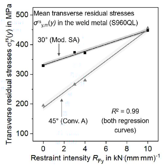
Figure 1.
Mean transverse residual stresses in the weld metal as a function of restraint intensity RFy for different component-like tests and for two different weld seam configurations [25].
Previous investigations by the authors showed, that weld metal in butt joints at reduced V-groove welded with Mod. SA can contain higher diffusible hydrogen concentrations when welding was carried out at higher deposition rates compared to wider V-groove welded with Conv. A due to the deeper weld penetration profile and the increased welding currents [12,27]. Independent of the seam configuration and arc process, the limited processing range when welding high-strength structural steels (low t8/5-cooling times) did not allow sufficient hydrogen effusion out the weld metal. After DHT at 250 °C for 4 h at 20 mm thick plates of S960QL, no diffusible hydrogen could be detected in the weld metal [27].
The studies so far have mainly referred to the resulting stresses during welding with restraint of shrinkage as a function of heat control, welding process and weld seam opening angle [25]. In addition, DHT was investigated with respect to hydrogen effusion out of the weld metal, but not for HAC prevention for component-like specimens. For investigation of hydrogen embrittlement, different test methods exist. Tests regarding the influence of diffusible hydrogen on degradation of different microstructures and steels are mainly carried out on electrochemically hydrogen charged tensile specimens [28,29,30,31]. When it comes to welding, there are numerous self-restraint and externally loaded test procedures for investigating HAC [32,33]. The externally loaded implant test was used to analyze the influence of diffusible hydrogen concentration [34] and different base materials or filler materials [35,36,37,38] on HAC in the HAZ. Investigations carried out using the Mod. SA in the implant test showed that the deeper weld penetration profile and the increased welding current result in higher diffusible hydrogen concentrations and longer time-to-failure of the specimens until fracture [39]. However, the critical implant stress for crack initiation was not affected. The most common self-restraint tests are the CTS (controlled thermal severity) test [40,41] and the TEKKEN test. The TEKKEN test with Y-groove was applied to determine required preheat temperatures or heat input to avoid HAC [4,42]. By applying acoustic emission analyses, also time of crack initiation could be determined [15,43]. The advantage of TEKKEN test is, that component-like specimens can be modeled due to the geometry and the correspondingly high restraint intensity. The test can be used to investigate HAC in the HAZ as well as in the weld metal.
The aim of the present study is to determine the HAC susceptibility in the HAZ and in the weld metal of a 960 MPa grade high-strength structural steel. The complex interactions of the influences of material, welding process and weld seam configuration on HAC are investigated using the TEKKEN test. Both solid wire and metal-cored wire are used to vary the diffusible hydrogen concentration. In addition, the welding residual stresses on the surface of the weld seam are considered. Acoustic emission analysis is also used to determine the time of crack initiation for different weld seam configurations. Finally, the effectiveness of DHT immediately after welding to prevent HAC is examined under high restraint of shrinkage.
2. Materials and Methods
2.1. Test Materials
For the investigations, the quenched and tempered high-strength structural steel S960QL (BM) according to EN 10025-6 [44] with a plate thickness of 20 mm was chosen. This steel is typically used in mobile crane construction and shows high susceptibility to HAC in GMAW [37,39]. The welds were carried out with micro-alloyed filler materials of the same type. The solid wire (SW) G 89 6 M Mn4Ni2CrMo according to ISO 16834-A [45] and the seamless metal-cored wire (MW) T 89 4 Mn2NiCrMo M M 1 H5 according to ISO 18276-A [46] with a diameter of 1.2 mm each were used. Table 1 and Table 2 show the chemical composition and the mechanical properties of the test materials. Table 2 also shows that SW leads to a slight undermatching and MW to a matching weld seam.

Table 1.
Chemical composition in wt.% of test materials (Fe—balance).
Table 2.
Mechanical properties of test materials.
2.2. TEKKEN Test and Welding Parameters
The restraint of shrinkage of a welded construction has a significant influence on the formation of HAC. Therefore, self-restraint specimens using the TEKKEN test were used for the systematic analysis of the cracking behavior under high restraint intensity as function of the seam configuration and the diffusible hydrogen concentration. According to ISO 17642-2 [47], TEKKEN samples have Y-seam configuration with a seam opening angle of 60°. In the present work, the seam configuration was adapted to the requirements of the Mod. SA. Therefore, the seam opening angle was reduced to 30°. In addition, the standard [47] contains the requirements to mechanically manufacture the TEKKEN samples from the specimen parts and to join them by anchor weld seams. To avoid possible welding distortion or stresses caused by anchor welds, the seam geometry was produced by means of electric discharge machining (EDM) from the solid material. Figure 2 shows the geometry of the TEKKEN sample and two variants for the seam configuration. Welding with the Conv. A was carried out at the seam configuration with a seam opening angle of α = 60°. The Mod. SA was used with a seam opening angle of α = 30°. In both cases, the angle of the notch was kept constant to ensure comparative stresses and strains at this location. The restraint intensity in the transverse direction of the TEKKEN sample with a seam opening angle of 60° for a sheet thickness of 20 mm is approximately RFy = 17 kN·(mm·mm)−1 [48]. This level is in the range of RFy of real welded components in shipbuilding or crane construction [25,49,50].
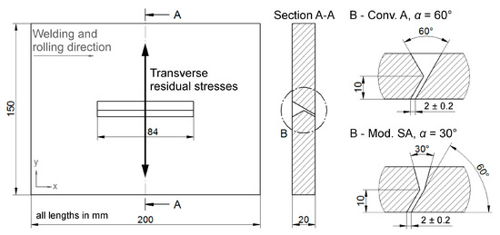
Figure 2.
Geometry of the TEKKEN samples with two different weld seam configurations.
Before welding, the surfaces to be welded were cleaned with acetone. Welding of the single-pass test welds took place with the arc processes and welding parameters from Table 3. ISO 14175-M21-ArC-18 [51] was used as shielding gas. In order to also increase the diffusible hydrogen concentration, a shielding gas mixture (81.5% Ar, 18% CO2 and 0.5% H2) was used in combination with solid wire. The gas flow rate was kept constant at 18 l/min in all welds. Analogous to previous investigations [12,27,39], the higher wire feed speed of the Mod. SA required an adjustment of the welding speed to maintain comparative heat inputs. In addition, to realize high cooling rates, and thus, crack–critical microstructures in weld metal and HAZ, all welds were performed without preheating. During cooling the temperature T(t) was recorded on the surface of the weld beads by a digital pyrometer to determine the t8/5-cooling times. To verify the effect of DHT for HAC prevention, additional TEKKEN samples were welded with subsequent DHT directly from the welding heat at a temperature of 250 °C for 4 h in a furnace. For this temperature and dwell time sufficient reduction of the diffusible hydrogen concentration in the weld metal could already be shown in previous investigations [27]. A total of nine TEKKEN samples were welded. Of these, three samples were subjected to DHT. After welding, the samples were stored for at least 48 h in accordance with the standard [47]. To determine the diffusible hydrogen concentration in the deposited arc weld metal, TEKKEN tests were accompanied by test welds produced according to ISO 3690 [52] with the processes and welding parameters from Table 3. For the analysis and detection of diffusible hydrogen carrier gas hot extraction (CGHE) with a G8 GALILEO (Bruker AXS GmbH, Karlsruhe, Germany) at a temperature of 400 °C [53] with coupled mass spectrometer (MS) ESD 1000 (InProcess Instruments Gesellschaft für Prozessanalytik mbH, Bremen, Germany) was used. More details about CGHE and MS can be found in [37,54].
Table 3.
Welding parameters for TEKKEN tests.
2.3. Acoustic Emission Analyses
Acoustic emission testing offers the possibility of registering HAC during the cooling process of a weld seam. In the present work, the acoustic emission technique helped to record the time until crack initiation during the cooling process as a function of the weld seam configuration. For this purpose, a piezo sensor was placed on the TEKKEN samples (α = 30° and 60°, welded with SW and shielding gas mixture with H2), see Figure 3a. Due to the temperature sensitivity of the sensor, it was placed on the samples after welding processing. To eliminate background noise as far as possible, both the welding power source and the control unit were switched off after welding, so that the acoustic measurement started two minutes after welding was finished. Acoustic signals were analyzed by means of high-frequency impulse measurement (HFIM) [55]. During this process, acoustic waves are detected by the sensors and converted in real time into a three-dimensional image (time, frequency and amplitude) by Fourier transformation, see Figure 3b.
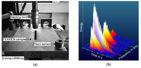
Figure 3.
Acoustic emission analysis for in situ monitoring of crack formation: (a) Piezo sensor placed on TEKKEN sample; (b) Exemplary image of a crack-typical signal 5 min after welding was finished at α = 60°.
2.4. Measurement of Local Residual Stresses
In all welded TEKKEN samples, the local transverse residual stresses were quantified via X-ray diffraction at the position x = 100 mm in weld metal, HAZ and base material, see Figure 2. In general, the determination of residual stresses by X-ray is based on Bragg’s law [56], Equation (1):
n · λ = 2 · dhkl · sinθ,
The monochromatic X-ray radiation with the intensity I0 and the wavelength λ hits the surface of the measuring point at the angle θ. A part of the radiation can be diffracted by reflection at the lattice planes (hkl). If the distance between two beams reflected at the distance dhkl is an integer factor n of the wavelength λ, the Bragg equation is fulfilled. In this case, the incident radiation is diffracted around 2θ and has the intensity I. Residual stresses change the distance of the lattice planes dhkl and thus, shift the interference of the X-rays. By means of equations of elasticity the displacement can be converted into stress values [57]. The analysis and calculation of the residual stress values in the present work was performed using the sin2ψ-method [56]. Table 4 gives an overview about the settings and specifications of the used mobile X-ray diffractometer Xstress G3 (Stresstech GmbH, Rennerod, Germany).
Table 4.
Experimental details for the X-ray diffraction.
2.5. Further Characterization of TEKKEN Samples
For the metallographic examinations, five cross sections were prepared from each welded test seam, distributed over the entire seam length. All metallographic samples were embedded, ground, polished, and etched with 2% Nital solution (HNO3). After the preparation of the samples, they were examined for cracks using light optical microscopy at 200x magnification. Cross sections containing cracks were examined for that, and the number of cracks and total crack length were determined. In addition, Vickers hardness tests with a test load of 49.03 N (HV5) were used to characterize the microstructure in weld metal, HAZ and base metal. For the observation of the segregation behavior of SW and MW, and especially for characterization of crack flanks, element mappings around cracks were performed with electron probe micro analysis (EPMA) and wavelength dispersive X-ray spectroscopy (WDX) at an increment of 1 µm. The work was performed with a micro probe JXA-8900 RL (JEOL GmbH, Freising, Germany) with an acceleration voltage of 15 kV and a probe current of 250 nA. In addition, micro hardness tests with a test load of 0.4903 N (HV0.05) at a distance of 5 µm in the area around cracks served for further characterization. For fractographic crack surface analysis the scanning electron microscope (SEM) VEGA3 (TESCAN, Brno—Kohoutovice, Czech Republic) was used.
3. Results and Discussion
3.1. Diffusible Hydrogen Concentration in Arc Weld Metal
Figure 4 shows the diffusible hydrogen concentration HD determined in the arc weld metal according to ISO 3690 for the used filler materials and arc processes. When using the solid wire, an average hydrogen concentration of approximately HD = 1 mL/100 g is present. In case of metal cored wire, the average HD increases up to almost 2 mL/100 g. Metal and flux cored wires can contain more total hydrogen amount compared to solid wires in delivery condition [58]. Thus, more hydrogen can be dissociated in the arc during welding and absorbed by the weld metal. Moreover, the results in Figure 4 show the tendency of slightly higher HD when using Mod. SA compared to weldments with Conv. A. This was already observed in investigations on butt joints with V-groove [12,27]. When using the standard M21 shielding gas the main source for diffusible hydrogen is the filler material itself. As a result, an increase of the wire feed speed with associated increase in welding current when using Mod. SA also can lead to higher diffusible hydrogen concentration. Using the gas mixture with a hydrogen addition of 0.5% results in average HD of about 6 mL/100 g, cf. Figure 4. As in this case the shielding gas is the main source for hydrogen, the difference between Conv. A and Mod. SA disappeared. A similar effect was observed by Wilhelm et al. [15] for different filler metals. Differences in HD between solid wire and flux cored wire disappeared when a shielding gas with additional hydrogen was used.
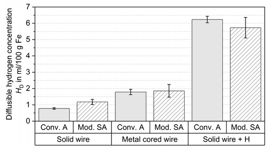
Figure 4.
Diffusible hydrogen concentration HD in the arc weld metal for the different used filler materials and arc processes determined according to ISO 3690; “+ H” is with shielding gas mixture containing 0.5% H2.
The diffusible hydrogen introduced into the weld metal can diffuse into highly stressed and strained areas which are located around the root notch in the TEKKEN test [59,60]. For the determined HD from Figure 4 the HAZ of the base material as well as the weld metals show a significant degradation of the mechanical properties with related risk to HAC [37,39,61]. By an adequate choice of welding parameters and heat control during welding HD can be lowered. However, for a complete release of diffusible hydrogen a DHT after welding is necessary. TEKKEN samples that have been subjected to DHT at 250 °C for 4 h can be assumed to consist no significant hydrogen in weld metal as has already been demonstrated by the authors in butt joints with V-groove on 20 mm thick plates [27].
3.2. Microstructure in Weld Metal and HAZ
As welding was performed without preheating low t8/5-cooling times were determined in the range of 3.5 s and 4.3 s. Figure 5 shows two Vickers hardness distributions across the base metal, HAZ and weld metal for the two different filler materials in TEKKEN samples with α = 30°. The base metal shows a hardness of (338 ± 7) HV5. In the HAZ the hardness increases to a maximum of 418 HV5 in case of welding with solid wire and 435 HV5 in case of metal cored wire. The weld metals show a hardness of (376 ± 10) HV5 to (382 ± 10) HV5. In addition to the carbon-related hardening in the CGHAZ, a softening can also be seen in the inter-critical HAZ (ICHAZ), see Figure 5. The minimum hardness is 290 HV5 and 304 HV5. This softening is well known for micro-alloyed quenched and tempered high-strength structural steels and can be related to tempering and transformation effects [62].
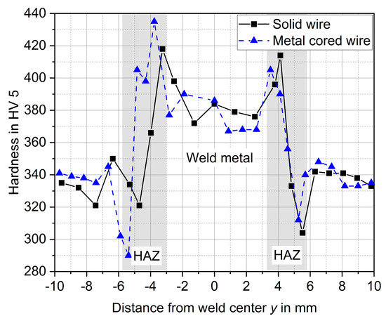
Figure 5.
Hardness distributions for two different filler materials at α = 30°.
Across all welded tests, hardness in CGHAZ is between 392 HV5 and 446 HV5. According to formulas of Dueren [63] the hardness of a fully martensitic microstructure HVM and for a fully bainitic microstructure HVB of the used S960QL is 433 HV10 and 275 HV10, respectively. It can therefore be concluded that the microstructure in the CGHAZ consists mainly of martensite with small amounts of bainite. Figure 6a shows an exemplary overview image of weld metal, CGHAZ and fine-grained HAZ (FGHAZ). The microstructure of CGHAZ in detail is shown in Figure 6b. In case of weld metal, a fully martensitic microstructure exists for t8/5-cooling times below 6 s [25].
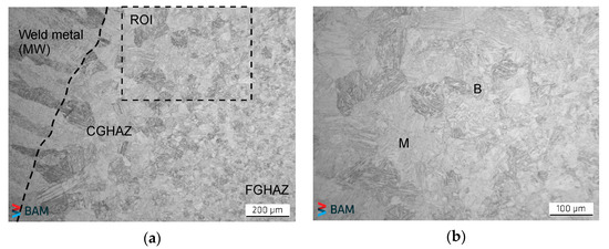
Figure 6.
Exemplary microstructure in TEKKEN sample (metal cored wire, α = 30°): (a) image by light optical microscopy with region of interest (ROI); (b) ROI in detail with microstructure in the CGHAZ—B and M are bainite and martensite.
Investigations with the same type of base and filler materials at diffusible hydrogen concentrations between 1.3 mL/100 g and 1.7 mL/100 g showed a high susceptibility to HAC in the CGHAZ using the externally loaded implant test [37,39]. Thus, it can be stated that on the one hand critical diffusible hydrogen concentrations are present in the weld metal, regardless of weld seam geometry and filler material. On the other hand, crack-critical microstructures with high hardness are present in the CGHAZ. However, it must be noted that the weld metal also contains increased hardness values compared to the base material. Therefore, a high risk for HAC in both, the weld metal and the HAZ must be assumed. An influence of DHT on the microstructure and the related hardness was not found in the present study as has already been described in [27].
3.3. Welding Residual Stresses
The determined residual stress distributions in transverse direction on the surface of the samples welded with solid wire are shown in Figure 7a for both seam configurations. The residual stress distributions are symmetrical for both samples and show compressive residual stresses in the base material as well as in the HAZ and tensile residual stresses in the center of the weld metal. The compressive residual stresses in the base material result from the surface treatment of the samples, as EDM required a prior sand blasting to remove the scale layer. The high tensile residual stresses in the weld metal are due to the comparatively high restraint intensity resulting from the specimen geometry and can also be attributed to inhomogeneous phase transformations [18]. At the seam opening angle of α = 60°, the maximum tensile residual stress is 690 MPa. For the narrower weld groove (α = 30°), it is 784 MPa and corresponds to about 84% of the nominal Rp0.2 proof stress of the filler material (930 MPa). The difference of 94 MPa between the two weld configurations can be attributed to the slightly higher heat input as a result of the increased arc energy (heat input) and the associated initiation of higher shrinking forces. In addition, the deeper weld penetration, and the higher depth-to-width ratio of the weld seam in case of α = 30°, can lead to inhomogeneous phase transformation, which causes tensile residual stresses on the weld seam surface [18].
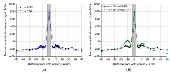
Figure 7.
Transverse residual stress distributions σrsy(y) on the surface of welded TEKKEN samples: (a) Influence of seam opening angle α; (b) Influence of DHT.
Figure 7b shows the residual stress distributions on the surface of welded samples with and without DHT for constant weld configuration. The sample without DHT shows maximum tensile residual stresses of 789 MPa in the weld metal compared to 784 MPa with DHT. For high-strength structural steels there are no microstructural changes at these low temperatures to be expected [64]. In addition, large temperature gradients are avoided by homogeneous DHT of the entire sample, which means that no additional stresses are initiated. The stresses in the HAZ or BM adjacent to the weld are higher in case of without DHT, see Figure 7b. This can be explained by the occurrence of root cracking (without DHT) in connection with stress redistribution for equilibrium reasons, which will be explained more in detail in the following.
3.4. Crack Formation in TEKKEN Samples
Regardless of the weld seam geometry (arc process) and filler metal used or hydrogen concentration are present, all welded TEKKEN samples without DHT show cracks starting from the HAZ at the area around the root notch and propagating through the weld metal to the weld seam surface, see Figure 8a,b. This crack profile is typical for TEKKEN samples made of high-strength structural steels [4,42,65]. These cracks could be completely avoided by DHT at 250 °C for 4 h, see Figure 8c,d. As there is no influence by DHT on the microstructure and residual stresses as already shown, it can be assumed that HAC can be avoided by complete hydrogen effusion in the first place. In one sample (α = 30°, welded with solid wire), the crack does not extend completely to the weld surface, reaching only about 70% of the weld height. Accordingly, the welding stresses in transverse direction in the sample are not completely relieved, causing still considerably high residual stresses at the weld seam surface, cf. Figure 7b. It is suggested that due to the cracking a stress redistribution results in an increase of the tensile residual stresses in the HAZ or BM adjacent to the weld, not occurring in the crack-free sample with DHT.
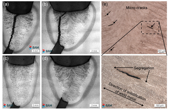
Figure 8.
Exemplary micrographs of the cross sections from the TEKKEN samples: (a) α = 30°, welded with metal cored wire; (b) α = 60°, welded with metal cored wire; (c) α = 30°, welded with solid wire with subsequent DHT; (d) α = 60°, welded with solid wire with subsequent DHT; (e) micro-cracks in weld metal.
In addition, in the weld metal micro- and macro-cracks occur, cf. Figure 8e. The location and orientation of the crack formation is parallel to the solidification direction of the weld metal around segregations. The length of the detected cracks varies between 62 µm and 2 mm. Figure 9 shows the total crack length and count, both accumulated over the five analyzed cross sections, for all used filler materials and weld seam opening angles. On the one hand, both an increased total crack length and a higher number of cracks are noticeable when using the solid wire compared to the metal cored wire. On the other hand, TEKKEN samples show a significantly increased crack occurrence under reduced weld seam opening angle. Furthermore, DHT does not lead to any prevention of these cracks.
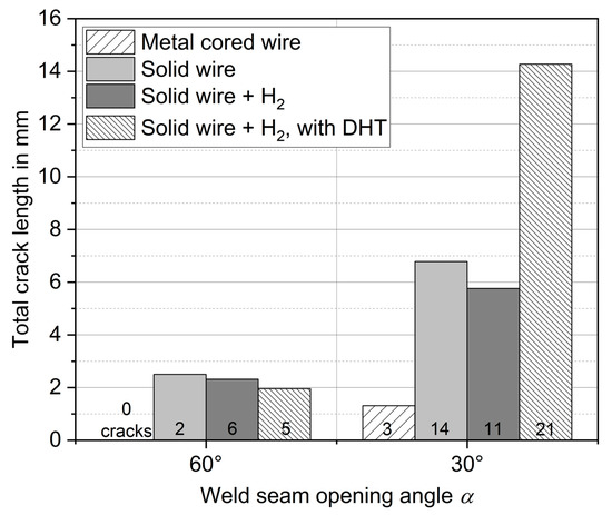
Figure 9.
Total crack length and number of micro- and macro-cracks in the weld metal for different filler materials and weld configurations.
Weld metal cracking in the presence of hydrogen is often related to chevron cracking in literature [66,67]. However, chevron cracks are located at approximately 45° angle to the axis of the welding direction. In the present study cracks are located along the direction of solidification of weld metal. As beyond that, complete hydrogen effusion by DHT does not lead to any avoidance of micro- and macro-cracks, it is reasonable to assume that cracks are related to hot cracking. Investigations by Heinze et al. [68] on the same type of materials show the same type of cracks in the weld metal. It was concluded that micro-crack formation is related to solidification cracking. However, an influence of hydrogen on crack formation could not be completely excluded. Furthermore, Tasak et al. [69] postulates that hot cracks can act as initiation sites for time-delayed HAC. Hydrogen diffuses into the areas around the micro-cracks and crack propagation occurs under high stresses or strains during cooling of the weld joint.
In particular, the fact that cracking is significantly more pronounced under reduced weld seam opening angle is evident in Figure 9. Thus, a design influence seems to be relevant for crack initiation. Phaoniam et al. [70] showed, that the depth-to-width ratio (d/w) of weld metal in laser welding can have a significant influence on the susceptibility to solidification cracking. From the work, it can be observed that the local strain increases as with d/w, and thus solidification cracking is promoted. In case of the TEKKEN samples, d/w for α = 30° and α = 60° is 1.4 and 1, respectively. Therefore, it can be assumed that local strains are higher for α = 30° which leads to higher cracking appearance. Furthermore, highest strains are located in the middle of the weld bead according to [70] which corresponds to the location of cracks found in the TEKKEN samples.
As Tasak et al. [69] already stated, those micro-cracks can act as initiation sites for HAC. Figure 10 shows the energy (dimensionless) from acoustic emission signals during cooling of the TEKKEN samples for two different weld seam opening angles. In both cases, the diffusible hydrogen concentrations are comparable because the main source for hydrogen was the shielding gas. In the case of the wider seam opening angle of α = 60°, crack-typical signals were registered up to a duration of 5 min after welding was finished, see Figure 10a. In contrast, with a reduced seam opening angle of α = 30°, cracking phenomena occurred up to 168 min after the end of welding, with the predominant signals being completed after 90 min, see Figure 10b. Thus, it can be concluded that the micro- and macro-cracks in the weld metal grow during the cooling process of the weld. Since significantly more crack sites are formed under reduced weld seam opening angle due to increased strain, the crack formation is also more pronounced during cooling. A detailed discussion of the micro-cracks in the weld metal and the influence of the filler metals on crack formation is discussed in the following section.
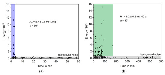
Figure 10.
Acoustic emission signals during cooling starting 2 min after welding: (a) α = 60°; (b) α = 30°; shielding gas used was gas mixture containing 0.5% H2.
3.5. Characterization of Cracks
3.5.1. Cracks Starting from the Root Notch
The topography of the surfaces of the cracked TEKKEN samples was carried out by SEM, see Figure 11. For low diffusible hydrogen concentration of HD = 1.2 mL/100 g, the crack surface located at the root notch shows a quasi-cleavage (QCl) topography, see Figure 11a. With increasing HD up to 1.9 mL/100 g and 5.7 mL/100 g, see Figure 11b,c, crack surfaces changes into mainly cleavage (Cl)-like topography.
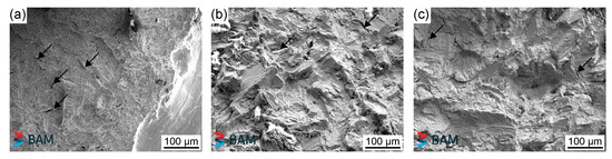
Figure 11.
Fracture topography of cracks starting from the root notch: (a) Quasi-cleavage (QCl) at HD = 1.2 mL/100 g; (b) cleavage (Cl) at HD = 1.9 mL/100 g; (c) Cl at HD = 5.7 mL/100 g; arrows indicate secondary cracks.
QCl topography on crack surface is common for low carbon steels in the presence of diffusible hydrogen [71]. With increasing HD, topography changes into more Cl-like facets with less deformation. According to Beachem [72], the fracture topography depends on the interaction of diffusible hydrogen and stress intensity. For low stress intensity, HAC is to be expected intergranular. As it can be seen in Figure 11, all cracks appeared transgranular. Cracks started in the HAZ located at the root notch, cf. Figure 8a,b. At this area significantly increased stresses and strains are present which lead to high stress intensity [59]. Therefore, cracks start to form transgranular. It could be also observed that all crack surfaces show the appearance of secondary cracks which are typical for hydrogen influence in high-strength structural steels. These cracks starting from the root notch could be clearly assigned to HAC, as SEM examinations showed. By means of DHT, a complete avoidance is likely, see Figure 8c,d.
3.5.2. Cracks in Weld Metal
In the following, the causes of crack formation in the weld metal are attempted to be determined based on chemical influences. Figure 12 shows overview images of micro-cracks for α = 30° when using solid wire as well as metal cored wire. Also included are associated element mappings by EPMA and colored illustrations of the micro hardness around the cracks. EPMA mappings show areas around cracks with enriched manganese (Mn), nickel (Ni) and sulfur (S) concentrations in case of solid wire. For the metal cored wire interdendritic segregations of Mn and Ni are present in direction of solidification. Enrichments of chromium (Cr) have also been discovered. However, segregations of Cr are not as pronounced as for Mn and Ni.
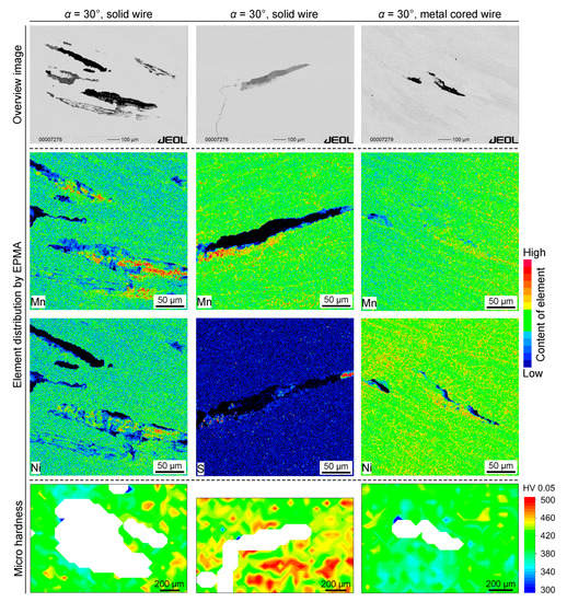
Figure 12.
Characterization of cracks in weld metal by electron probe micro analysis (EPMA) and micro hardness measurement; indication of qualitatively element concentration by EPMA.
Solidification cracking is known for low carbon (C) and low S filler metal wire [73]. The amount of filler material relative to the base material decreases at high welding speed which is the case for Mod. SA at α = 30°. In addition, C content in the weld metal increases due to higher C content of the base material. It follows that in the solid–liquid region, the amount of austenite increases as well as the S content in the liquid phase. The formation of a Fe-MnS-FeS eutectic then leads to a decreased solidification temperature. Higher local strains increase solidification cracking. With lower welding speed solidification cracking decreases which is the case for Conv. A at α = 60°. As the S content in the solid wire (0.013 wt.%) is significantly increased compared to S content in metal cored wire (0.005 wt.%) the solid wire shows higher cracking susceptibility. Heinze et al. [68] also found increased S content on the crack surfaces and indicated an increased cracking with increased welding speed. If excessive hydrogen concentration exists in the weld metal which is the case for the used shielding gas with hydrogen addition another cracking is described by Tasak et al. [69]. Manganese oxides may lead to gaps between grains during solidification. Excessive hydrogen amounts then create a hydrogen gas layer in between the grains leading to hot cracking.
The used metal cored wire is known to have interdendritic segregations with elevated concentrations of Mn and Ni [74,75]. In addition, elevated C contents were identified by the authors [75]. This suggests that the C-enriched zones are layers of retained austenite according to [76]. However, electron backscatter diffraction (EBSD) and X-ray diffraction analysis, in the present study, to localize retained austenite around cracks, did not provided robust data and therefore no reliable results. Thus, it is to be assumed that a reduced hardness is present at these islands of retained austenite and that cracks are formed due to increased local strains. Since lower strains are present at α = 60° compared to α = 30°, no cracks were detected when the metal cored wire was used at wider groove. No direct correlation exhibited between hardness and crack incidence, see Figure 12.
Aucott et al. [77] describe a three-stage model for solidification cracking with nucleation of intergranular hot cracks. Afterwards, cracks are connected via intergranular fracture with increased strain and propagate through interdendritic hot tearing. This model can explain the topography of crack surfaces shown in Figure 13. No clear structure of hot cracks is evident, but slight melting on individual grains. Similar crack phenomena were also found by Heinze et al. [68].
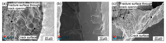
Figure 13.
Topography of opened micro-cracks of solid wire at α = 30° for (a) HD = 5.7 mL/100 g and (b) HD = 1.2 mL/100 g and (c) of metal cored wire at α = 60° with DHT.
4. Conclusions
The present work dealt with hydrogen-assisted cracking of the high-strength steel S960QL with similar micro-alloyed filler metals in the self-restraint TEKKEN test. The use of two arc process variants with approximately the same heat input and different deposition rates, as well as the choice of two filler metals and shielding gases, made it possible to investigate the influence of the weld geometry and diffusible hydrogen concentration on the HAC behavior. The analysis of the diffusible hydrogen concentration, the local transverse residual stresses near the surface and the metallographic investigation of the cracks that occurred were essential for this. Furthermore, the effectiveness of a dehydrogenation heat treatment to prevent HAC under high restraint of shrinkage was investigated. The following conclusions can be drawn:
- The level of diffusible hydrogen concentration depends on the choice of filler metal. Slightly elevated hydrogen levels may be present when using the metal cored wire;
- The use of the Mod. SA with increased deposition rate can lead to slightly higher hydrogen concentrations on average compared to the use of the Conv. A. This has already been demonstrated on butt joints with V-groove [12,27] and occurs mainly at higher wire feed speed and increased welding currents;
- In all TEKKEN samples, crack-critical microstructures with high hardness are present in both, the weld metal and HAZ at the selected welding parameters;
- The geometry of the TEKKEN samples imposes high stress conditions on the weld. Transverse tensile residual stress maxima were determined in the weld center, which were up to about 84% of the nominal Rp0.2 proof stress of the filler metal. When welding components under increased restraint intensity, a high risk of HAC can therefore be assumed for the selected materials;
- Regardless of weld configuration and diffusible hydrogen concentration, all TEKKEN samples showed HAC, starting from the root notch in the HAZ. This HAC could be completely avoided by a dehydrogenation heat treatment immediately after welding;
- The weld metal exhibits a considerable occurrence of micro- and macro-cracks, which can be attributed to both, design and chemical influences by the filler metals. When the solid wire was used under reduced weld seam opening angle, a high susceptibility to cracking was identified;
- Chemical analyses and investigations by SEM indicate solidification cracking;
- Further investigations are necessary for a detailed characterization of the origin of the cracks in the weld metal. Furthermore, it must also be clarified to what extend these cracks serve as an initiation site for HAC during cooling. It can be assumed that hydrogen diffuses to the crack tips and thus promotes time-delayed crack formation.
Author Contributions
Conceptualization, T.S. and N.S.; methodology, T.S., N.S. and D.S.; validation, D.S. and T.K.; investigation, T.S. and N.S.; data curation, T.S. and N.S.; writing—original draft preparation, T.S.; writing—review and editing, N.S., D.S. and T.K.; visualization, T.S. and N.S.; supervision, T.K.; project administration, T.S. and T.K. All authors have read and agreed to the published version of the manuscript.
Funding
This research received no external funding.
Institutional Review Board Statement
Not applicable.
Informed Consent Statement
Not applicable.
Data Availability Statement
Experimental methods and results are available from the authors.
Acknowledgments
The authors would like to thank Bundesanstalt für Materialforschung und -prüfung (BAM) for financial and technical support. The assistance of Michaela Buchheim with SEM imaging and Gabriele Oder with EPMA is also greatly appreciated. Further thanks are addressed to Mareike Kirstein, Marina Marten and Arne Kromm for their support. Thanks also go to Ines Krempe from Otto von Guericke University Magdeburg for the preparations of metallographic samples.
Conflicts of Interest
The authors declare no conflict of interest.
References
- Ahlblom, B.; Hansson, P.; Narström, T. Martensitic Structural Steels for Increased Strength and Wear Resistance. Mater. Sci. Forum 2007, 539–543, 4515–4520. [Google Scholar] [CrossRef]
- Hulka, K.; Kern, A.; Schriever, U. Application of Niobium in Quenched and Tempered High-Strength Steels. Mater. Sci. Forum 2005, 500–501, 519–526. [Google Scholar] [CrossRef]
- Shi, Y.; Sun, K.; Cui, S.; Zeng, M.; Yi, J.; Shen, X.; Yi, Y. Microstructure Evolution and Mechanical Properties of Underwater Dry and Local Dry Cavity Welded Joints of 690 MPa Grade High Strength Steel. Materials 2018, 11, 167. [Google Scholar] [CrossRef]
- Węglowski, M.S.; Zeman, M. Prevention of cold cracking in ultra-high strength steel Weldox 1300. Arch. Civ. Mech. Eng. 2014, 14, 417–424. [Google Scholar] [CrossRef]
- Schneider, C.; Ernst, W.; Schnitzer, R.; Staufer, H.; Vallant, R.; Enzinger, N. Welding of S960MC with undermatching filler material. Weld. World 2018, 62, 801–809. [Google Scholar] [CrossRef]
- Schnitzer, R.; Zügner, D.; Haslberger, P.; Ernst, W.; Kozeschnik, E. Influence of alloying elements on the mechanical properties of high-strength weld metal. Sci. Technol. Weld. Join. 2017, 22, 536–543. [Google Scholar] [CrossRef]
- Yurioka, N.; Suzuki, H. Hydrogen assisted cracking in C-Mn and low alloy steel weldments. Int. Mater. Rev. 1990, 35, 217–249. [Google Scholar] [CrossRef]
- Lynch, S. Hydrogen embrittlement phenomena and mechanisms. Corros. Rev. 2012, 30, 105–123. [Google Scholar] [CrossRef]
- Djukic, M.B.; Bakic, G.M.; Sijacki Zeravcic, V.; Sedmak, A.; Rajicic, B. The synergistic action and interplay of hydrogen embrittlement mechanisms in steels and iron: Localized plasticity and decohesion. Eng. Fract. Mech. 2019, 216, 106528. [Google Scholar] [CrossRef]
- Fydrych, D.; Świerczyńska, A.; Tomków, J. Diffusible hydrogen control in flux cored arc welding process. Key Eng. Mater. 2014, 597, 171–178. [Google Scholar] [CrossRef]
- Kannengiesser, T.; Lausch, T. Diffusible Hydrogen Content Depending on Welding and Cooling Parameters. Weld. World 2012, 56, 26–33. [Google Scholar] [CrossRef]
- Schaupp, T.; Rhode, M.; Kannengiesser, T. Influence of welding parameters on diffusible hydrogen content in high-strength steel welds using modified spray arc process. Weld. World 2018, 62, 9–18. [Google Scholar] [CrossRef]
- Świerczyńska, A.; Fydrych, D.; Rogalski, G. Diffusible hydrogen management in underwater wet self-shielded flux cored arc welding. Int. J. Hydrogen Energy 2017, 42, 24532–24540. [Google Scholar] [CrossRef]
- Tuerker, M. Diffusible hydrogen content in submerged arc welds of a S960 type steel. Mater. Test. 2016, 58, 561–568. [Google Scholar] [CrossRef]
- Wilhelm, E.; Mente, T.; Rhode, M. Waiting time before NDT of welded offshore steel grades under consideration of delayed hydrogen-assisted cracking. Weld. World 2021, 65, 947–959. [Google Scholar] [CrossRef]
- ES EN 1011-2. Recommendations for Welding of Metallic Materials—Part 2: Arc Welding of Ferritic Steels; Beuth Verlag GmbH: Berlin, Germany, 2001. [Google Scholar]
- AWS D1.1/D1.1M. Structural Welding Code—Steel; American Welding Society (AWS): Miami, FL, USA, 2015. [Google Scholar]
- Nitschke-Pagel, T.; Dilger, K. Sources and Consequences of Residual Stresses due to Welding. Mater. Sci. Forum 2014, 783–786, 2777–2785. [Google Scholar] [CrossRef]
- Schaupp, T.; Schroepfer, D.; Kromm, A.; Kannengiesser, T. Welding residual stresses in 960 MPa grade QT and TMCP high-strength steels. J. Manuf. Process. 2017, 27, 226–232. [Google Scholar] [CrossRef]
- Wongpanya, P.; Boellinghaus, T.; Lothongkum, G.; Kannengiesser, T. Effects of preheating and interpass temperature on stresses in S1100QL multi-pass butt-welds. Weld. World 2008, 52, 79–92. [Google Scholar] [CrossRef]
- Gáspár, M. Effect of Welding Heat Input on Simulated HAZ Areas in S960QL High Strength Steel. Metals 2019, 9, 1226. [Google Scholar] [CrossRef]
- Mente, T.; Boellinghaus, T.; Schmitz-Niederau, M. Heat treatment Effects on The Reduction of Hydrogen in Multi-Layer High-Strength Weld Joints. Weld. World 2012, 56, 26–36. [Google Scholar] [CrossRef]
- Steppan, E.; Mente, T.; Boellinghaus, T. Numerical investigations on cold cracking avoidance in fillet welds of high-strength steels. Weld. World 2013, 57, 359–371. [Google Scholar] [CrossRef]
- Norrish, J. Recent gas metal arc welding (GMAW) process developments: The implications related to international fabrication standards. Weld. World 2017, 61, 755–767. [Google Scholar] [CrossRef]
- Schröpfer, D. Adaptierte Wärmeführung zur Optimierung Schweißbedingter Beanspruchungen und Eigenschaften Höherfester Verbindungen. Ph.D. Thesis, Otto von Guericke University, Magdeburg, Germany, Shaker Verlag, Aachen, Germany, 2017. [Google Scholar]
- Schroepfer, D.; Kromm, A.; Kannengiesser, T. Optimization of welding loads with narrow groove and application of modified spray arc process. Weld. World 2017, 61, 1077–1087. [Google Scholar] [CrossRef]
- Schaupp, T.; Rhode, M.; Yahyaoui, H.; Kannengiesser, T. Influence of heat control on hydrogen distribution in high-strength multi-layer welds with narrow groove. Weld. World 2019, 63, 607–616. [Google Scholar] [CrossRef]
- Depover, T.; Laureys, A.; Pérez Escobar, D.; Van den Eeckhout, E.; Wallaert, E.; Verbeken, K. Understanding the Interaction between a Steel Microstructure and Hydrogen. Materials 2018, 11, 698. [Google Scholar] [CrossRef]
- Qu, J.; Feng, M.; An, T.; Bi, Z.; Du, J.; Yang, F.; Zheng, S. Hydrogen-Assisted Crack Growth in the Heat-Affected Zone of X80 Steels during in Situ Hydrogen Charging. Materials 2019, 12, 2575. [Google Scholar] [CrossRef] [PubMed]
- Rudomilova, D.; Prošek, T.; Traxler, I.; Faderl, J.; Luckeneder, G.; Schimo-Aichhorn, G.; Muhr, A. Critical Assessment of the Effect of Atmospheric Corrosion Induced Hydrogen on Mechanical Properties of Advanced High Strength Steel. Metals 2021, 11, 44. [Google Scholar] [CrossRef]
- Villalobos, J.C.; Del-Pozo, A.; Mayen, J.; Serna, S.; Campillo, B. Hydrogen embrittlement susceptibility on X-120 microalloyed steel as function of tempering temperature. Int. J. Hydrogen Energy 2020, 45, 9137–9148. [Google Scholar] [CrossRef]
- Kannengiesser, T.; Boellinghaus, T. Cold cracking tests—An overview of present technologies and applications. Weld. World 2013, 57, 3–37. [Google Scholar] [CrossRef]
- Kurji, R.; Coniglio, N. Towards the establishment of weldability test standards for hydrogen-assisted cold cracking. Int. J. Adv. Manuf. Technol. 2015, 77, 1581–1597. [Google Scholar] [CrossRef]
- Saini, N.; Pandey, C.; Mahapatra, M.M. Effect of diffusible hydrogen content on embrittlement of P92 steel. Int. J. Hydrogen Energy 2017, 42, 17328–17338. [Google Scholar] [CrossRef]
- Savage, W.F.; Nippes, E.F.; Sawhill, J.M., Jr. Hydrogen Induced Cracking During Implant Testing of Alloy Steels. Weld. J. 1976, 55, 400–407. [Google Scholar]
- Sawhill, J.M., Jr.; Dix, A.W.; Savage, W.F. Modified Implant Test for Studying Delayed Cracking. Weld. J. 1974, 53, 554s–560s. [Google Scholar]
- Schaupp, T.; Ernst, W.; Spindler, H.; Kannengiesser, T. Hydrogen-assisted cracking of GMA welded 960 MPa grade high-strength steels. Int. J. Hydrogen Energy 2020, 45, 20080–20093. [Google Scholar] [CrossRef]
- Yadav, U.; Pandey, D.; Saini, N.; Thakre, J.G.; Mahapatra, M.M. Study on Hydrogen-Assisted Cracking in High-Strength Steels by Using the Granjon Implant Test. Metallogr. Microstruct. Anal. 2017, 6, 247–257. [Google Scholar] [CrossRef]
- Schaupp, T.; Rhode, M.; Yahyaoui, H.; Kannengiesser, T. Hydrogen-assisted cracking in GMA welding of high-strength structural steels using the modified spray arc process. Weld. World 2020, 64, 1997–2009. [Google Scholar] [CrossRef]
- Tomków, J. Weldability of Underwater Wet-Welded HSLA Steel: Effects of Electrode Hydrophobic Coatings. Materials 2021, 14, 1364. [Google Scholar] [CrossRef]
- Tomków, J.; Rogalski, G.; Fydrych, D.; Łabanowski, J. Advantages of the Application of the Temper Bead Welding Technique during Wet Welding. Materials 2019, 12, 915. [Google Scholar] [CrossRef]
- Alexandrov, B.; Theis, K.; Streitenberger, M.; Herold, H.; Martinek, I. Cold Cracking in Weldments of Steel S 690 QT. Weld. World 2005, 49, 64–73. [Google Scholar] [CrossRef]
- Shiraiwa, T.; Kawate, M.; Briffod, F.; Kasuya, T.; Enoki, M. Evaluation of hydrogen-induced cracking in high-strength steel welded joints by acoustic emission technique. Mater. Design 2020, 190, 108573. [Google Scholar] [CrossRef]
- DIN EN 10025-6. Hot Rolled Products of Structural Steels—Part 6: Technical Delivery Conditions for Flat Products of High Yield Strength Structural Steels in the Quenched and Tempered Condition; Beuth Verlag GmbH: Berlin, Germany, 2020. [Google Scholar]
- DIN EN ISO 16834. Welding Consumables—Wire Electrodes, Wires, Rods and Deposits for Gas Shielded Arc Welding of High Strength Steels—Classification; Beuth Verlag GmbH: Berlin, Germany, 2012. [Google Scholar]
- DIN EN ISO 18276. Welding Consumables—Tubular Cored Electrodes for Gas-Shielded and Non-Gas-Shielded Metal Arc Welding of High Strength Steels—Classification; Beuth Verlag GmbH: Berlin, Germany, 2017. [Google Scholar]
- DIN EN ISO 17642-2. Destructive Tests on Welds in Metallic Materials—Cold Cracking Tests for Weldments—Arc Welding Processes—Part 2: Self-Restraint Tests; Beuth Verlag GmbH: Berlin, Germany, 2005. [Google Scholar]
- Schwenk, C.; Kannengiesser, T.; Rethmeier, M. Restraint conditions and welding residual stresses in self-restrained cold cracking test. In Trends in Welding Research, Proceedings of the 8th International Conference, Pine Mountain, GA, USA, 1–6 June 2008; Stan, A.D., DebRoy, T., DuPont, J.N., Koseki, T., Smartt, H.B., Eds.; ASM International: Novelty, OH, USA, 2009; pp. 766–771. [Google Scholar]
- Satoh, K.; Ueda, Y.; Kihara, H. Recent trends of research into restraint stresses and strains in relation to weld cracking. Weld. World 1973, 11, 133–156. [Google Scholar]
- Satoh, K.; Ueda, Y.; Matsui, S.; Natsume, M.; Terasaki, T.; Fukuda, K.; Tsuji, M. Japanese studies on structural restraint severity in relation to weld cracking. Weld. World 1977, 15, 155–189. [Google Scholar]
- DIN EN ISO 14175. Welding Consumables—Gases and Gas Mixtures for Fusion Welding and Allied Processes; Beuth Verlag GmbH: Berlin, Germany, 2008. [Google Scholar]
- DIN EN ISO 3690. Welding and Allied Processes—Determination of Hydrogen Content in Arc Weld Metal; Beuth Verlag GmbH: Berlin, Germany, 2018. [Google Scholar]
- Rhode, M.; Schaupp, T.; Muenster, C.; Mente, T.; Boellinghaus, T.; Kannengiesser, T. Hydrogen determination in welded specimens by carrier gas hot extraction—A review on the main parameters and their effects on hydrogen measurement. Weld. World 2019, 63, 511–526. [Google Scholar] [CrossRef]
- Salmi, S.; Rhode, M.; Jüttner, S.; Zinke, M. Hydrogen determination in 22MnB5 steel grade by use of carrier gas hot extraction technique. Weld. World 2015, 59, 137–144. [Google Scholar] [CrossRef]
- Tillmann, W.; Walther, F.; Luo, W.; Haack, M.; Nellesen, J.; Knyazeva, M. In Situ Acoustic Monitoring of Thermal Spray Process Using High-Frequency Impulse Measurements. J. Therm. Spray Technol. 2018, 27, 50–58. [Google Scholar] [CrossRef]
- Macherauch, E.; Müller, P. Das sin2ψ Verfahren zur röntgenografischen Spannungsmessung. Z. Angew. Phys. 1961, 13, 305–312. [Google Scholar]
- Withers, P.J.; Bhadeshia, H.K.D.H. Residual stress. Part 1—Measurement techniques. Mater. Sci. Technol. 2001, 17, 355–365. [Google Scholar] [CrossRef]
- Bailey, N.; Coe, F.R.; Gooch, T.G.; Hart, P.H.M.; Jenkins, N.; Pargeter, R.J. Welding Steels without Hydrogen, 2nd ed.; Woodhead Publishing Ltd.: Novelty, OH, USA, 1973; pp. 102–106. [Google Scholar]
- Stadtaus, M.; Michailov, V.; Wohlfahrt, H. Numerical calculation of the main factors on cold cracking. Mater. Werksttech. 2003, 34, 145–151. [Google Scholar] [CrossRef]
- Yan, C.; Jiang, X.; Yuan, Y.; Ji, X.; Zhang, K. Cold cracking susceptibility of X100 pipeline steel. China Weld. 2019, 28, 25–33. [Google Scholar]
- Zimmer, P.; Seeger, D.M.; Boellinghaus, T. Hydrogen permeation and related material properties of high strength structural steels. In High Strength Steels for Hydropower Plants, Proceedings of High Strength Steels for Hydropower Plants, Graz, Austria, 5–6 July 2005; Cerjak, H., Ed.; Verlag der Technischen Universität Graz: Graz, Austria, 2005; p. 17. [Google Scholar]
- Zhang, L.; Kannengiesser, T. HAZ softening in Nb-, Ti- and Ti + V-bearing quenched and tempered steel welds. Weld. World 2016, 60, 177–184. [Google Scholar] [CrossRef]
- Düren, C. Formulae for calculating the maximum hardness in the heat-affected zone of welded joints. In Proceedings of the Annual Assembly of the International Institute of Welding, Tokyo, Japan, 12–19 July 1986. Document IX-1437-86. [Google Scholar]
- Dhua, S.K.; Mukerjee, D.; Sarma, D.S. Influence of tempering on the microstructure and mechanical properties of HSLA-100 steel plates. Metall. Mater. Trans. A 2001, 32, 2259–2270. [Google Scholar] [CrossRef]
- Hanzaei, A.T.; Marashi, S.P.H.; Ranjbarnodeh, E. The effect of hydrogen content and welding conditions on the hydrogen induced cracking of the API X70 steel weld. Int. J. Hydrogen Energy 2018, 43, 9399–9407. [Google Scholar] [CrossRef]
- Allen, D.J.; Chew, B.; Harris, P. The Formation of Chevron Cracks in Submerged Arc Weld Metal. Weld. J. 1982, 61, 212s–221s. [Google Scholar]
- Mota, J.M.F.; Apps, R.L. “Chevron Cracking”—A New Form of Hydrogen Cracking in Steel Weld Metals. Weld. J. 1982, 61, 222s–228s. [Google Scholar]
- Heinze, C.; Michael, T.; Pittner, A.; Rethmeier, M. Microcrack Formation During Gas Metal Arc Welding of High-Strength Fine-Grained Structural Steel. Acta Metall. Sin. Engl. Lett. 2014, 27, 140–148. [Google Scholar] [CrossRef]
- Tasak, E.; Ziewiec, A.; Adamiec, J. The role of hydrogen in weld cracking processes—A new look at the problem. Weld. Int. 2011, 25, 409–414. [Google Scholar] [CrossRef]
- Phaoniam, R.; Shinozaki, K.; Yamamoto, M.; Kadoi, K.; Nishijima, A.; Yamamoto, M. Solidification cracking susceptibility of modified 9Cr1Mo steel weld metal during hot-wire laser welding with a narrow gap groove. Weld. World 2014, 58, 469–476. [Google Scholar] [CrossRef]
- Merson, E.D.; Myagkikh, P.N.; Poluyanov, V.A.; Merson, D.L.; Vinogradov, A. Quasi-cleavage hydrogen-assisted cracking path investigation by fractographic and side surface observations. Eng. Fract. Mech. 2019, 214, 177–193. [Google Scholar] [CrossRef]
- Beachem, C.D. A new model for hydrogen-assisted cracking (hydrogen embrittlement). Metall. Trans. 1972, 3, 441–455. [Google Scholar] [CrossRef]
- Amaya, T.; Yonezawa, T.; Ogawa, K.; Peltonen, M.J.; Hänninen, H. Solidification Cracking Mechanism of Carbon Steel Weld Metal. Weld. J. 2018, 97, 55s–64s. [Google Scholar]
- Haslberger, P.; Ernst, W.; Schneider, C.; Holly, S.; Schnitzer, R. Influence of inhomogeneity on several length scales on the local mechanical properties in V-alloyed all-weld metal. Weld. World 2018, 62, 1153–1158. [Google Scholar] [CrossRef]
- Haslberger, P.; Ernst, W.; Schnitzer, R. High resolution imaging of martensitic all-weld metal. Sci. Technol. Weld. Join. 2017, 22, 336–342. [Google Scholar] [CrossRef]
- Caballero, F.G.; Miller, M.K.; Clarke, A.J.; Garcia-Mateo, C. Examination of carbon partitioning into austenite during tempering of bainite. Scripta. Mater. 2010, 63, 442–445. [Google Scholar] [CrossRef]
- Aucott, L.; Huang, D.; Dong, H.B.; Wen, S.W.; Marsden, J.; Rack, A.; Cocks, A.C.F. A Three-Stage Mechanistic Model for Solidification Cracking During Welding of Steel. Metall. Mater. Trans. A 2018, 49, 1674–1682. [Google Scholar] [CrossRef]


Publisher’s Note: MDPI stays neutral with regard to jurisdictional claims in published maps and institutional affiliations. |
© 2021 by the authors. Licensee MDPI, Basel, Switzerland. This article is an open access article distributed under the terms and conditions of the Creative Commons Attribution (CC BY) license (https://creativecommons.org/licenses/by/4.0/).