Abstract
Microstructure and irradiation hardening of V-4Cr-4Ti alloys with different yttrium (Y) contents were studied by self-ion irradiation at 550 °C via TEM and nano-indentation test technology. The peak damage of the V-4Cr-4Ti-xY alloy (x = 0, 0.1, 0.5, and 1, wt.%) irradiated by 2.5 MeV self-ion (V2+) is 8 dpa. Dense dislocation loops were observed in all vanadium alloy samples after irradiation. With the increase of Y content, both average size and number density of dislocation loops using g = <110> near the pole [001] decreased, while the irradiation hardness increment first decreased and then increased. In order to better reduce the irradiation hardening, it is considered that the addition of 0.1 wt.% Y in V-4Cr-4Ti alloy is reasonable.
1. Introduction
Vanadium alloy is considered a promising structure material in nuclear fusion reactors due to its excellent low activation, high temperature mechanical properties, liquid lithium compatibility, and radiation swelling resistance. It is well known that the vanadium alloy has a better comprehensive performance when the content of Ti element and Cr element is about 3–5% (wt.%) [1,2,3]. V-4Cr-4Ti alloys exhibit important advantages as candidate structural materials for fusion reactor first walls and blanket applications [4,5].
The impurity elements (such as C, N, and O) would be introduced inevitably in the vanadium alloy during the preparation process, and then complex precipitates could be formed, especially Ti-rich precipitates, which would decrease thermal stability and cause low-temperature irradiation brittleness of the vanadium alloy [6]. In general, multi-component alloys inhibit cavity generation and radiation hardening [7]. By adding the Y element, the production of Ti-rich precipitates could be inhibited, since the O element can be well combined to form Y2O3 precipitates, in order to improve low-temperature irradiation brittleness, hardening under high temperature conditions, and irradiation resistance of the vanadium alloy [8,9]. It was also found that the addition of the Y element could effectively inhibit the formation of interstitial dislocation loops, vacancies, and Ti-rich precipitates in the vanadium alloys under neutron irradiation [10,11].
Ion irradiation is widely used to simulate neutron irradiation, which has the advantages of a short time, high damage level, and no radioactivity. Heavy ions (such as Fe10+, Cu2+, and Ni2+) were mostly used to investigate the irradiation of vanadium alloys to obtain a higher damage dose [12,13,14]. However, the lattice parameters of these ions and V are mismatching, which may lead to an experimental phenomenon deviating from the real situation. For example, the addition of Y elements seemed to have little effect on irradiation hardening when irradiated with Cu2+ ion to 7.6 dpa at 200 °C via nano-indentation test, which differs from the result of neutron experiments [15]. Therefore, the influence the addition of the Y element on irradiation hardening of vanadium alloys needs to be further evaluated by self-ion irradiation, which is considered to be the better method to simulate neutron irradiation [16,17].
At the same time, few systematic studies have focused on the relationship between microstructure and hardening of V-4Cr-4Ti alloys with different Y contents irradiated by self-ion at the ambient temperature of the fusion reactor. In this study, a V-4Cr-4Ti-xY (x = 0, 0.1, 0.5, and 1, wt.%) alloy was irradiated by V2+ ion at 550 °C, the effect of Y addition on the dislocation loops and hardening induced by self-ion irradiation in V-4Cr-4Ti alloy were studied. The possible mechanism is explained, and the reasonable value of Y element addition is provided from the point of view of radiation resistance.
2. Materials and Methods
2.1. Self-Ion Irradiation
V-4Cr-4Ti-xY alloys (x = 0, 0.1, 0.5, and 1, wt.%, named as S0, S1, S2, and S3) were used as experimental materials in this study, which were prepared using arc melting on a water-cooled copper plate under highly purified Ar atmosphere with high purity elemental materials. The preparation process was as follows: high purity argon was filled in a high vacuum chamber, the Ti block was melted before each melting of samples to reduce the oxygen elements and other impurities, and then the arc-melted ingot was flipped and remelted at least five times to ensure thorough mixing and chemical homogeneity. After annealing at 900 °C for 2 h, the samples were cut into sheets of 2 mm × 3 mm × 0.5 mm. All samples were polished with 800#, 1000#, 2000#, and 5000# SiC abrasive paper successively, and then mechanically polished with 2#, 1#, and 0.5# abrasive pastes successively. To remove the polishing damage from the previous step, they were finally electrochemical polished by 25% sulfuric acid and 75% ethanol polishing solution (in volume percent) at room temperature at a voltage of 10 V for 30 s.
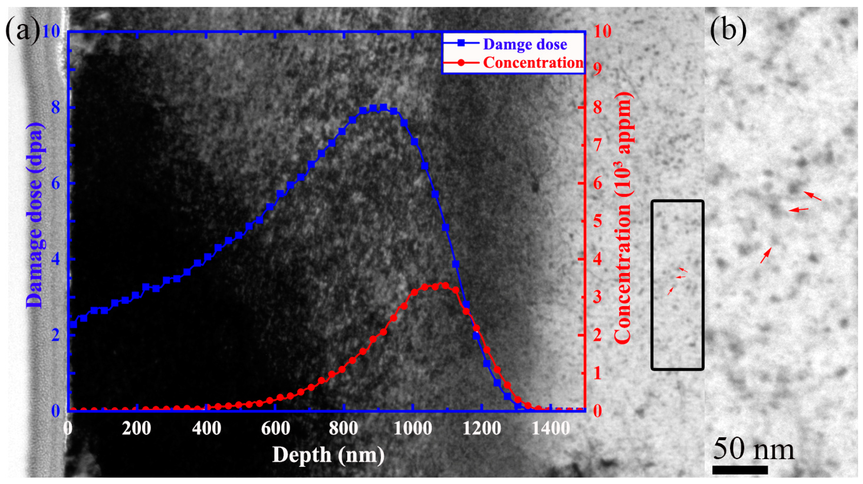
Samples were irradiated with 2.5 MeV self-ion (V2+) performed at 550 °C with a fluence of 9.17 × 10¹⁵ ions cm−2 on an 2 × 1.7 MV tandem accelerator in the Accelerator Laboratory of Wuhan University. The vacuum degree was maintained at 2.2 × 10⁻⁴ Pa, the irradiation time was 12 h, and the temperature was monitored with a thermocouple during the irradiation, within an error of ±5 °C. The corresponding Stopping and Range of Ions in Matter (SRIM) calculation results and experimental results are shown in Figure 1a, Figure 1b is the magnification image of the black dotted line on the right side of Figure 1a. The damage at the peak was about 8 dpa (corresponding depth is 915 nm), and at the statistics area was about 4.06–5.44 dpa (corresponding to 400–600 nm). According to the SRIM calculation, the threshold displacement energy of V, Cr and Ti are 40 eV, 40 eV and 30 eV, respectively [18]. The nominal displacement rate was defined as 1.85 × 10⁻⁴ dpa/s at the damage peak (915 nm).
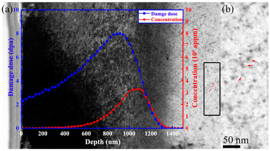
Figure 1.
(a) SRIM calculation of damage and concentration under 2.5 MeV V2+ irradiation with a fluence of 9.17 × 10¹⁵ ions cm−2 in V-4Cr-4Ti alloy, (b) the magnification image of the black dotted line on the right side of Figure 1a.
2.2. TEM Observation
The irradiated samples were prepared by the focused ion beam (FIB) method, which was performed with Helios G4 UX Dual Beam FIB (FEI, Brno, Czech Republic). The specific steps were as follows: firstly, a layer of Pt film was deposited in the selected area, and then a thick layer of film was prepared by trenching the deposited area with a 30 keV Ga+ beam. The 2 μm thin sheet was then cut from the samples and attached to the TEM grid by a nano-manipulator and platinum deposition. Using a series of lower beams, the thin layer was thinned to a thickness of 80 nm. Finally, a 2 keV Ga+ beam was used to clean the wafers to minimize the FIB damage introduced by the Ga+ beam. Little black dots (~5 nm) were introduced inevitably as shown in the matrix which is marked by the red arrow in Figure 1. All FIB samples were observed by JEM-2100 transmission electron microscope (JEOL, Tokyo, Japan) with a resolution of 0.23 nm per pixel at the Wuhan University Analysis and Testing Center.
2.3. Nano-Indentation Test
A nano-indentation test was carried out on the Nano Indenter *G200 produced by Agilent Technologies (Agilent Technologies Inc, Santa Clara, CA, USA) The test methods were G-series Standard Hardness. The strain rate was set as 0.05 s−1, the depth of indentation was up to 1000 nm, and the distance between indentations was greater than 50 μm.
3. Results
3.1. TEM Observation of Microstructure
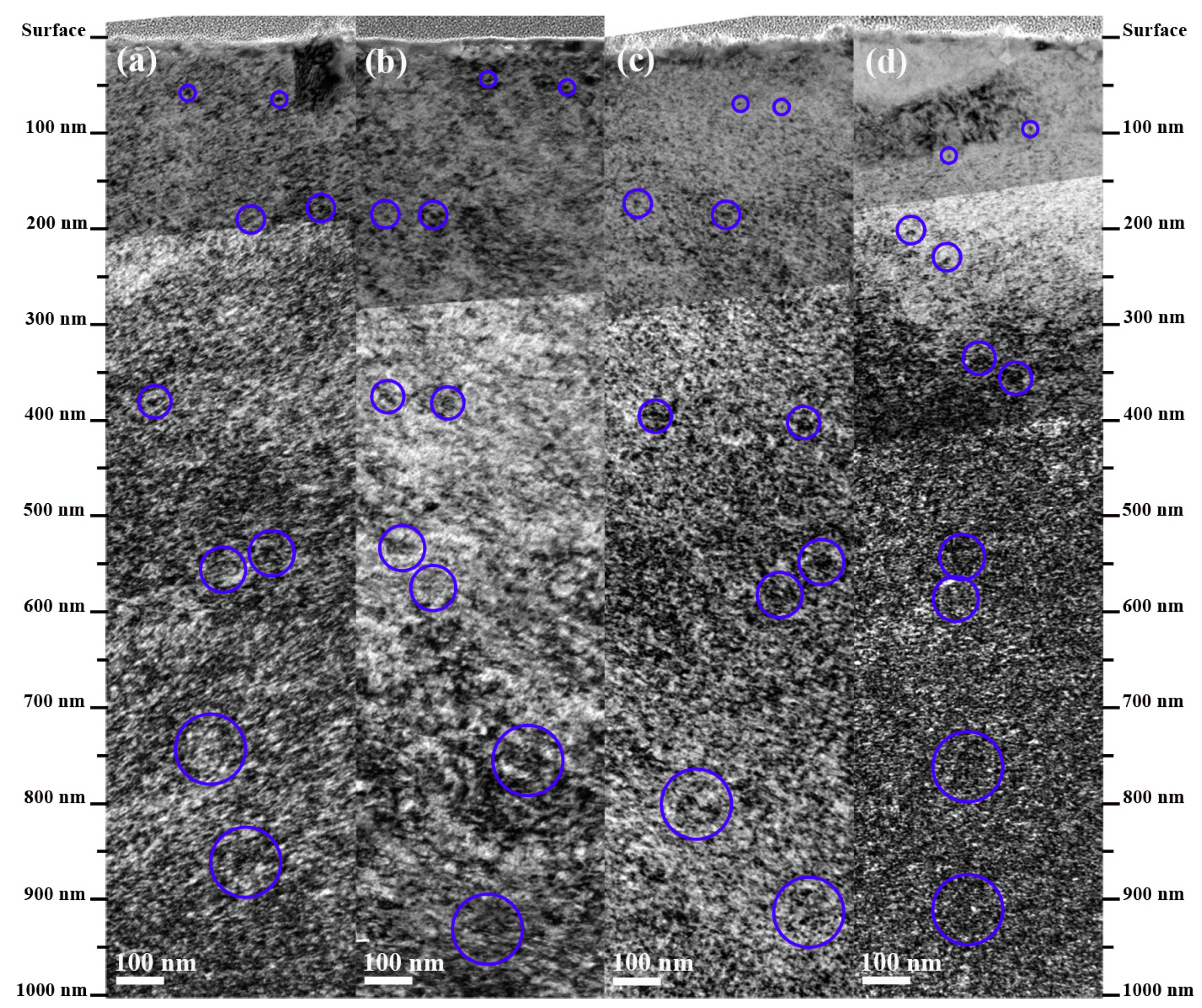
Figure 2 presents a bright field micrograph of the microstructure of V-4Cr-4Ti-xY alloy samples from the surface to 1000 nm after vanadium ion irradiation using g = 110 in a foil oriented near the pole [001]. Unambiguously, dense dislocation loops were observed in all irradiated samples, and the size of dislocation loops changed obviously with the irradiation depth (0–1000 nm). On the near surface of the samples, little black dots can be seen, whose size is close to while the density is higher than that of the matrix. With the depth increasing to ~200 nm (3.05 dpa), the dislocation loops with sizes less than 5 nm appeared in the samples. When the depth increased to 400–600 nm (4.06–5.44 dpa), the dislocation loops with sizes less than 5 nm and a size range of 5–10 nm were aggregated and grew, then the phenomenon of the dislocation loops with sizes less than 5 nm and a size range of 5–10 nm wrapped in dislocation loops with a size larger than 10 nm appeared. When the depth is greater than 600 nm (5.44 dpa), the dislocation loops with sizes larger than 10 nm grew larger, and the phenomenon of the dislocation loops with sizes larger than 10 nm wrapping the dislocation loops with sizes less than 5 nm is more obvious.
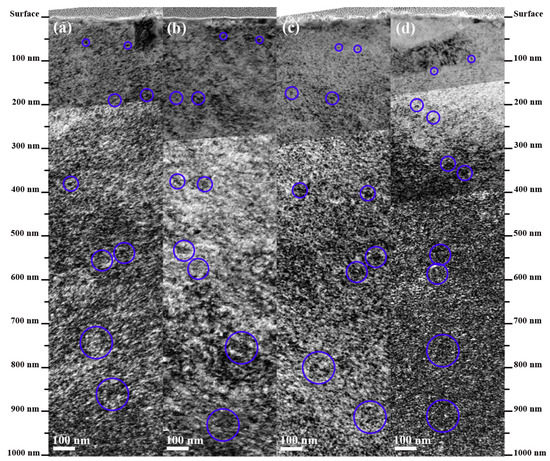
Figure 2.
Microstructure of (a) S0, (b) S1, (c) S2, and (d) S3 under self-ion irradiation using g = 110 near the pole [001]. (The blue circles represent typical dislocation loops structures.)
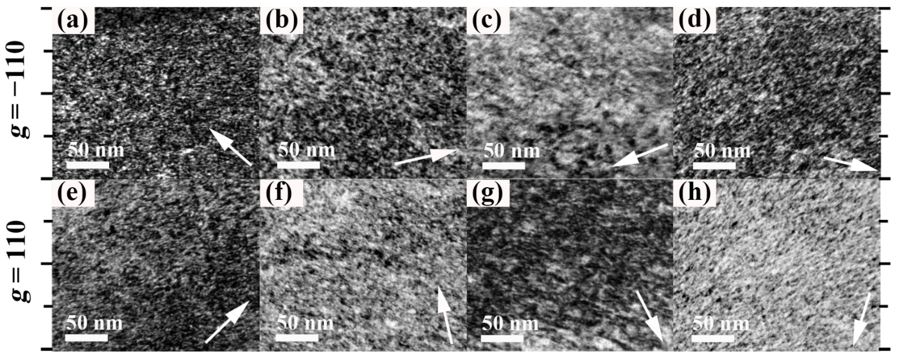
As shown in Figure 2, when the depth exceeds 600 nm, the size of the dislocation loops becomes larger and larger, and the phenomenon of the large dislocation loops wrapping the dislocation loops with sizes less than 5 nm is more serious. In order to exclude the surface effect and the effect of high concentration self-ion implantation near the damage peak, the range of 400–600 nm is selected to facilitate the discrimination and statistics. Figure 3 shows a TEM image of V-4Cr-4Ti-xY alloy samples in this depth range, which were taken under the weak beam conditions of g = −110 and g = 110, near the pole [001], respectively. The size and number densities of dislocation loops at the same position and under different g conditions in the four samples were statistically analyzed. At least 3 areas of ~200 nm × 500 nm were used for each TEM image, and the sum of all effectively counted loops is 5452, 3750, 3480, and 2857 for S0, S1, S2, and S3, respectively. The density and size measurements are summarized in Table 1, which were carried out by Adobe Photoshop CC 2018.link (Adobe, San Jose, CA, USA) and Image-ProPlus (Trial version, Media Cybernetics, Rockville, MD, USA) software. It can be found that the average size and number densities of the dislocation loops are the largest in the S0 without Y. With the increase of Y content, the average size and number densities of the dislocation loops in the samples gradually decrease.
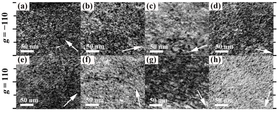
Figure 3.
Bright field images of (a,e) S0, (b,f) S1, (c,g) S2, and (d,h) S3 at the same position in the depth range of 400–600 nm under g = <110> conditions near the pole [001]. (The white arrow indicates the direction of the g diffraction.)

Table 1.
Average size and number density of dislocation loops using g = <110> near the pole [001] and hardness increment values of the nano-indentation experiment results.
3.2. Irradiation Hardening
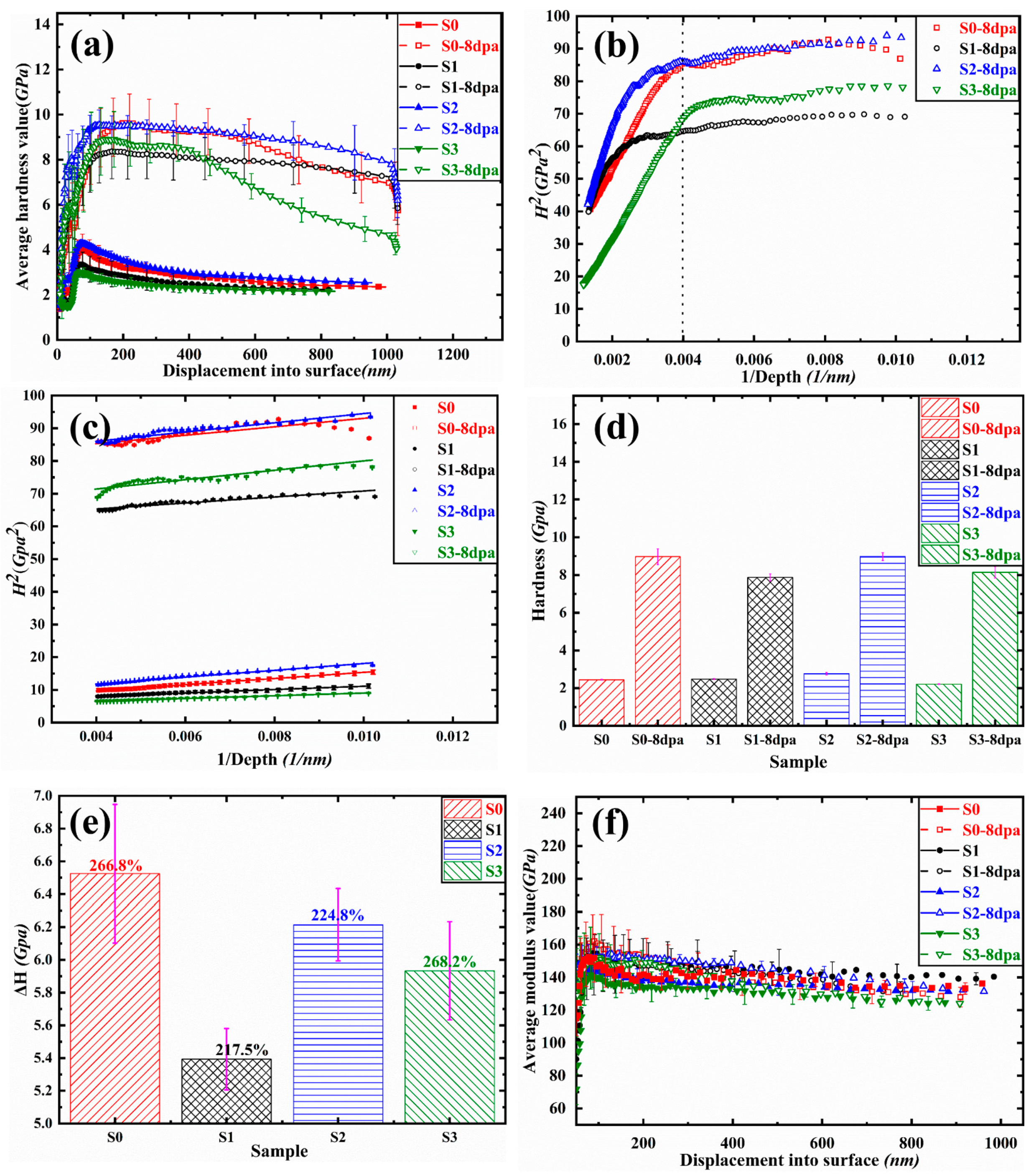
For the irradiation hardening, at least 10 points were tested for each sample before and after irradiation using nano-indentation test. Additionally, the distance between indentations was greater than 50 μm. After plotting the obtained data into a curve, some curves seriously deviating from the overall trend (called bad points) were deleted, and the average value was obtained as shown in Figure 4a. For the un-irradiated samples, when the indentation depth is greater than 50 nm, the hardness decreases with the increase of the indentation depth, which is called the indentation size effect (ISE). In order to exclude the ISE, the following Nix-Gao model is generally adopted [19]:
where H0 is the hardness at infinite depth, H is the hardness measured at depth h, and h* is the characteristic length related to the material itself and the shape of the indenter. At the same time, in order to avoid the nano-indentation hardness being affected by the surface conditions of the samples, such as the roughness, we chose to discard the data from the surface to the depth range of 100 nm [20].
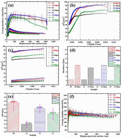
Figure 4.
The pictures of (a) mean nano-indentation hardness curve, (b) fitting curve of hardness in the range of 100–1000 nm, (c) fitting curve of hardness in the range of 100–250 nm, (d) comparison of hardness increment before and after irradiation, (e) ΔH and hardening rate, and (f) average curve of Young’s modulus.
The irradiated area will form a hardening layer whose hardness is different from that of the substrate, and the curve obtained by the irradiated area will be affected by the non-irradiated substrate, that is, the soft substrate effect (SSE) [21]. In order to exclude the influence of the SSE, the depth range of curve fitting needs to be accurately selected first. Figure 4b plots H02-1/h in the depth range of 100–1000 nm, it can be seen that all of the irradiated samples show different trends before and after the depth of 250 nm. Above 250 nm, H02 decreases rapidly with a decrease of 1/h, that is, the hardness decreases rapidly with the increase of depth. The curve between 100 and 250 nm is relatively smooth, indicating that this depth range is a hardening area not affected by the substrate. Therefore, the 100–250 nm region was selected for fitting to obtain the real hardness after irradiation. Data in the range of 100–250 nm were selected for fitting before and after irradiation, and the obtained H02-1/h curve is shown in Figure 4c. In order to directly reflect the change of hardness before and after irradiation, the fitting value of Figure 4c is represented in Figure 4d, each sample showed obvious hardening after irradiation. Hardness increment and hardening rate before and after irradiation are shown in Figure 4e. The specific calculation method is as follows: hardness increment, (ΔH) = (H0irr − H0unirr), represented by a bar chart; hardening rate = (H0irr − H0unirr)/H0unirr. Compared with the samples without Y addition, the hardening increment of the samples with Y addition decreased, and the hardness increment of S1 was the least. Figure 4f is the average curve of Young’s modulus of samples before and after irradiation, which is obtained by the nano-indentation test. For all samples, Young’s modulus is approximated as 140 GPa, which is an important parameter in the following dispersion barrier hardening model (DBH) calculation.
4. Discussion
4.1. The Effect of Y Addition on the Size and Number Densities of the Dislocation Loops
As summarized in Figure 5 with the increase of the Y addition, the average size and number densities of the dislocation loops decreased in the V-4Cr-4Ti-xY alloy samples after irradiation. It is reported that the movable gap O atoms in the matrix were conducive to the nucleation of dislocation loops between 150 and 350 °C [22], so it could be speculated that the migration of O would be further strengthened at 550 °C And it is found that the addition of the Y element had an obvious purifying effect on the O element in V-4Cr-4Ti alloys [23]. Thus, the O content is the largest in S0 without Y addition, and so it is not hard to understand that the average size and number densities of the dislocation loops are the largest in S0 without Y addition. The experimental relationship between the content of the O element in the matrix and the addition of Y is given as follows [23]:
where C is the O content in the matrix after the addition of Y, C0 and ΔCY are matrix of the original O content and adding amount of Y respectively, α = 70 wppm O/0.1 wt.% Y, which is a fitting value of the experiment result.
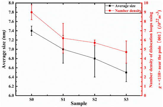
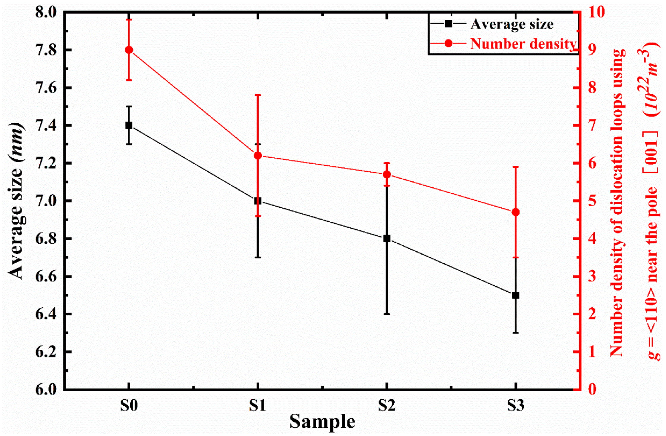
Figure 5.
Size and number density of dislocation loops using g = <110> near the pole [001] (1022 m−3).
Thus, the O content in the matrix would decrease with the increase of Y addition according to the formula above. Compared with S0, the number densities’ decrease rate is 31.11%/0.1 wt.%Y, 7.33%/0.1 wt.%Y, and 4.78%/0.1 wt.%Y for S1, S2, and S3, respectively, and the average size decrease rate is 5.41%/0.1 wt.%Y, 1.62%/0.1 wt.%Y, and 1.22%/0.1 wt.%Y for S1, S2, and S3, respectively. As a result, the addition amount of 0.1wt %Y in V-4Cr-4Ti alloy is considered to be reasonable.
At the same time, the addition of alloying elements (Al, Si, Y) could decrease the vacancy formation energies () and the migration energy of interstitial atoms () in the diluted V-X alloys (X = Ti, Cr, Al, Si, or Y) [24]. The is 2.34 eV, 2.31 eV, 2.20 eV, and 1.36 eV for pure vanadium, V-Al, V-Si, and V-Y alloys, respectively. Obviously, the Y atom exhibits strong interaction with vacancy, since only the atomic size of the Y atom is significantly different from the host V atom. Moreover, it was reported that the addition of alloying elements in vanadium alloy could decrease the migration energy of vacancies () [25]. Considering the strong interaction between Y and vacancy, it was also believed that the addition of Y could increase interstitial atom migration energy, inhibit interstitial atoms agglomeration, and thus inhibit the dislocation loops’ growth. It can be reasonably explained that the average size of the dislocation loops decreases with the increase of the addition amount of Y.
Compared with dislocation loops in S0, the decrease rate of the number densities and the size decreased of that in S3 is 47.78% and 12.16%, indicating that the effect of Y content on the dislocation loops nucleating is far greater than the effect on the interstitial atom migration.
4.2. Irradiation Hardening
It is well established that dislocation loops are assumed to act as barriers to gliding dislocations in the slip plane and impede their movements, therefore resulting in radiation hardening of vanadium alloy [22]. The hardness increment could be estimated in terms of their size and density. However, it is difficult to establish an accurate relationship between microstructure and radiation hardening. A large number of studies on irradiation hardening are related to the perspective of yield stress: ΔH ≈ 3δy [26], and δy can be obtained with the barrier hardening model to calculate (DBH), as follows:
where Δτ is shear stress, M is the Taylor factor (3.06 for BCC metal), α is the barrier strength (α = 0.5) [15], b = 0.262 nm for vanadium, μ = E/2(1 + ν), and E is the Young’s modulus given by the nano-indentation test (E = 140 GPa), as shown in Figure 4f, the value of ν is 0.35 for vanadium. N and d are the average number density and the average size of dislocation loops. The equation showed that the hardness change is proportional to the square root of the product of the defect density and size. As a result, the hardness increment contributed by dislocation loops would decrease with the increase of Y addition. However, the trend of hardness increment results calculated by the DBH model are quite different from the test results of the nano-indentation test, as shown in Table 1 and Figure 4e. With the increase of Y addition, the irradiation hardness increment first decreased and then increased and the hardness increment of S1 was the least.
On one hand, it was found that the obtained α values could not well reflect the situation at high temperature in irradiated V-4Cr-4Ti and V-4Cr-4Ti-0.15Y by 2.4 MeV, Cu2+ at 200 °C [15]. At the same time, the dislocation network formed by the superposition of the high density dislocation loops will have a much greater obstacle to the dislocation lines than the result predicted by the model. On the other hand, besides dislocation loops, precipitates, and other defects (bubbles, void, and so on) could also contribute to the hardening of vanadium alloy [27]. It is reported that the samples with large precipitate exhibited a relatively lower irradiation hardening rate than the ones with smaller precipitate, which attributes to the distinct aggregation of He atoms at the interface between the larger precipitate and matrix in the V-4Cr-4Ti alloy. In our work, small vacancy clusters were formed, however, their size might be too small to be distinguished by TEM, so no void could be found in all samples. With the increase of the addition of Y element, the size and density of Ti-rich precipitate decrease [28], the interface between Ti-rich precipitates and matrix becomes smaller, which might contribute to the higher hardness. Thus, the results calculated by the DBH model which were contributed by dislocation loops are quite different from the test results of the nano-indentation test.
At the same time, it must be pointed out that because of the invisibility criterion (g × b = 0), the density of the dislocation loops using g = <110> near pole [001] is less than the real density of the dislocation loops, and the contribution of the indistinguishably small (<5 nm) dislocation loops generated by irradiation to hardening cannot be ignored [29]. The contribution of these factors to hardening can hardly be accurately reflected by the DBH model. What is more, The DBH model is used to estimate hardening based on the sizes and number density of loops only in a specific area of the irradiated layer (between 400 and 600 nm). It should be expected that the calculated hardness is different from the nano-indentation data since the plastic deformation will take place in much bigger volumes. How to choose more appropriate parameters and methods and more accurately evaluate the influence of dislocation loops on irradiation hardening still requires further study. The decrease of O content will reduce the irradiation hardening [30], the results obtained by nano-indentation can illustrate this point well. Compared with S0, the hardness increment of S1, S2, and S3 decreased. However, compared with the S1 sample, the hardness increment of S2 increased obviously. In addition, the hardening rate also decreased first and then increased, with the minimum at 0.1 wt.%Y and almost the same at 1 wt.%Y without Y addition. This indicates that the addition amount of Y has a maximum effect on reducing hardness, and excessive Y may enhance hardening due to the enhanced pinning effect on dislocation loops under irradiation conditions.
5. Conclusions
The effect of Y addition on the microstructure and irradiation hardening in V-4Cr-4Ti alloys under self-ion (V2+) irradiation at 550 °C was investigated. Conclusions are as follows:
- Dense dislocation loops could be found after irradiation in all V-4Cr-4Ti-xY alloys. With the increase of Y addition, the size and number densities of dislocation loops under the g = <110> condition near pole [001] decrease.
- Obvious irradiation hardening was found in all V-4Cr-4Ti-xY alloys. With the increase of Y addition, the hardness increment first decreases and then increases, according to the nano-indentation test.
- Considered comprehensively, the component of V-4Cr-4Ti-0.1Y alloy is much more advantageous and deserves further study compared with other kinds of V-4Cr-4Ti-xY alloys in this paper.
Author Contributions
Conceptualization, H.L., F.L. (Fengfeng Luo) and L.G.; methodology, H.L. and L.G.; validation, F.L. (Fengfeng Luo) and L.G.; investigation, H.L., F.L. (Fengfeng Luo), Y.C., J.W., Q.L., F.L. (Fang Li) and X.Z.; analysis, H.L. and L.G.; supervision, L.G.; resources, F.L. (Fengfeng Luo) and L.G.; data curation, H.L. and F.L. (Fengfeng Luo); writing—original draft preparation, H.L.; writing—review and editing, F.L. (Fengfeng Luo) and L.G.; project administration, F.L. (Fengfeng Luo) and L.G.; funding acquisition, F.L. (Fengfeng Luo) and L.G. All authors have read and agreed to the published version of the manuscript.
Funding
The authors received financial support from the key research and development program of Jiangxi Province, China (No. 20181BBH80006, 20192BBHL80010, and 20203BBE53031), the National Natural Science Foundation of China (No. 11775162), and the key research and development program of Jiangxi Academy of Sciences (No. 2020-YZD-19).
Data Availability Statement
Data presented in this article are available at request from the corresponding author.
Acknowledgments
The authors would like to thank the help of the Analysis Testing Center of Wuhan University for supporting TEM observation and the Micro and Nano Fabrication Laboratory, Center for Nanoscience and Nanotechnology, Wuhan University for the assistance of TEM specimen preparation.
Conflicts of Interest
The authors declare no conflict of interest.
References
- Kurtz, R.J.; Abe, K.; Chernov, V.M.; Hoelzer, D.T.; Matsui, H.; Muroga, T.; Odette, G.R. Recent Progress on Development of Vanadium Alloys for Fusion. J. Nucl. Mater. 2004, 329–333, 47–55. [Google Scholar] [CrossRef]
- Muroga, T.; Nagasaka, T.; Abe, K.; Chernov, V.M.; Matsui, H.; Smith, D.L.; Xu, Z.Y.; Zinkle, S.J. Vanadium Alloys—Overview and Recent Results. J. Nucl. Mater. 2002, 307–311, 547–554. [Google Scholar] [CrossRef]
- Zinkle, S.J.; Matsui, H.; Smith, D.L.; Rowcliffe, A.F.; Van Osch, E.; Abe, K.; Kazakov, V.A. Research and Development on Vanadium Alloys for Fusion Applications. J. Nucl. Mater. 1998, 258–263, 205–214. [Google Scholar] [CrossRef]
- Muroga, T.; Chen, J.M.; Chernov, V.M.; Kurtz, R.J.; Le Flem, M. Present Status of Vanadium Alloys for Fusion Applications. J. Nucl. Mater. 2014, 455, 263–268. [Google Scholar] [CrossRef]
- Cao, X.; Li, Q.; Shi, Y.; Wu, D.; Xue, X. Preparation of v–4cr–4ti Alloys from Mixed Oxides via Electro-Deoxidation Process in Molten Salt. Metals 2020, 10, 1067. [Google Scholar] [CrossRef]
- Tyumentsev, A.N.; Korotaev, A.D.; Pinzhin, Y.P.; Ditenberg, I.A.; Litovchenko, S.V.; Shuba, Y.V.; Shevchenko, N.V.; Drobishev, V.A.; Potapenko, M.M.; Chernov, V.M. Effect of the Modes of Thermomechanical Treatment on the Formation of the Multiphase and Grain Structure of V-4Ti-4Cr Alloys. J. Nucl. Mater. 2004, 329–333, 429–433. [Google Scholar] [CrossRef]
- Su, Y.; Xia, S.; Huang, J.; Liu, Q.; Liu, H.; Wang, C.; Wang, Y. Irradiation Behaviors in Bcc Multi-Component Alloys with Different Lattice Distortions. Metals 2021, 11, 706. [Google Scholar] [CrossRef]
- Nagasaka, T.; Muroga, T.; Hino, T.; Satou, M.; Abe, K.; Chuto, T.; Iikubo, T. Impurity Behavior in V-4Cr-4Ti-Y Alloys Produced by Levitation Melting. J. Nucl. Mater. 2007, 367–370, 823–828. [Google Scholar] [CrossRef] [Green Version]
- Qiu, G.; Zhan, D.; Li, C.; Qi, M.; Yang, Y.; Jiang, Z.; Zhang, H. Effects of Yttrium on Microstructure Stability and Tensile Properties of China Low Activation Martensitic Steel. Metals 2019, 9, 446. [Google Scholar] [CrossRef] [Green Version]
- Kobayashi, S.; Tsuruoka, Y.; Nakai, K.; Kurishita, H. Effect of Neutron Irradiation on the Microstructure and Hardness in Particle Dispersed Ultra-Fine Grained V-Y Alloys. J. Nucl. Mater. 2004, 329–333, 447–451. [Google Scholar] [CrossRef]
- Watanabe, H.; Yamasaki, K.; Higashijima, A.; Taguma, H.; Nagasaka, T.; Muroga, T. Microstructural Changes of Y-Doped V-4Cr-4Ti Alloys after Ion and Neutron Irradiation. Nucl. Mater. Energy 2016, 9, 447–450. [Google Scholar] [CrossRef] [Green Version]
- Ding, J.; Yang, S.; Zhu, B.; Liu, H.; Liu, G.; Zhou, L.; Zhan, Q.; Wan, F. Twins Induced by High-Temperature Ion Irradiation in Body-Centered Cubic V-4Cr-4Ti Alloy. Scr. Mater. 2019, 162, 377–381. [Google Scholar] [CrossRef]
- Ochiai, K.; Watanabe, H.; Muroga, T.; Yoshida, N.; Matsui, H. Microstructural Evolution in Vanadium Irradiated during Ion Irradiation at Constant and Varying Temperature. J. Nucl. Mater. 1999, 271–272, 376–380. [Google Scholar] [CrossRef]
- Chernov, I.I.; Stal’tsov, M.S.; Kalin, B.A.; Zaw, A.K.; Drozhzhina, M.V.; Nikolaeva, I.D.; Romanov, V.A.; Bazhal, S.V.; Glotov, A.I.; Lagov, P.B. Particularities of Vanadium Microstructure Development During Irradiation by 7.5 MeV Ni2+ Ions at 650 °C. At. Energy 2015, 118, 400–404. [Google Scholar] [CrossRef]
- Miyazawa, T.; Nagasaka, T.; Kasada, R.; Hishinuma, Y.; Muroga, T.; Watanabe, H.; Yamamoto, T.; Nogami, S.; Hatakeyama, M. Evaluation of Irradiation Hardening of Ion-Irradiated V-4Cr-4Ti and V-4Cr-4Ti-0.15Y Alloys by Nanoindentation Techniques. J. Nucl. Mater. 2014, 455, 440–444. [Google Scholar] [CrossRef]
- Wang, B.; Haque, M.A.; Tomar, V.; Hattar, K. Self-Ion Irradiation Effects on Mechanical Properties of Nanocrystalline Zirconium Films. MRS Commun. 2017, 7, 595–600. [Google Scholar] [CrossRef]
- Shao, L.; Wei, C.C.; Gigax, J.; Aitkaliyeva, A.; Chen, D.; Sencer, B.H.; Garner, F.A. Effect of Defect Imbalance on Void Swelling Distributions Produced in Pure Iron Irradiated with 3.5 MeV Self-Ions. J. Nucl. Mater. 2014, 453, 176–181. [Google Scholar] [CrossRef]
- Zhang, Y.F.; Du, J.K.; Liu, P.P.; Zheng, P.F.; Yang, S.W.; Wan, F.R.; Zhan, Q. Response of Microstructure and Hardening to Deuterium Ion Irradiation InV-4Cr-4Ti-1.8Y-0.4Ti3SiC2 and V-4Cr-4Ti Alloy. Fusion Eng. Des. 2020, 159. [Google Scholar] [CrossRef]
- Nix, W.D.; Gao, H. Indentation Size Effects in Crystalline Materials: A Law for Strain Gradient Plasticity. J. Mech. Phys. Solids 1998, 46, 411–425. [Google Scholar] [CrossRef]
- Pharr, G.M.; Herbert, E.G.; Gao, Y. The Indentation Size Effect: A Critical Examination of Experimental Observations and Mechanistic Interpretations. Annu. Rev. Mater. Res. 2010, 40, 271–292. [Google Scholar] [CrossRef]
- Saha, R.; Nix, W.D. Effects of the Substrate on the Determination of Thin Film Mechanical Properties by Nanoindentation. Acta Mater. 2002, 50, 23–38. [Google Scholar] [CrossRef]
- Candra, Y.; Fukumoto, K.; Kimura, A.; Matsui, H. Microstructural Evolution and Hardening of Neutron Irradiated Vanadium Alloys at Low Temperatures in Japan Material Testing Reactor. J. Nucl. Mater. 1999, 271–272, 301–305. [Google Scholar] [CrossRef]
- Chuto, T.; Satou, M.; Hasegawa, A.; Abe, K.; Muroga, T.; Yamamoto, N. Effects of Small Amount of Additional Elements on Control of Interstitial Impurities and Mechanical Properties of V-4Cr-4Ti-Si-Al-Y Alloys. J. Nucl. Mater. 2004, 326, 1–8. [Google Scholar] [CrossRef]
- Zhang, C.; Zhang, P.; Li, R.; Zhao, J.; Dong, C. Stability and Migration of Vacancy in V-4Cr-4Ti Alloy: Effects of Al, Si, y Trace Elements. J. Nucl. Mater. 2013, 442, 370–376. [Google Scholar] [CrossRef]
- Nishizawa, T.; Sasaki, H.; Ohnuki, S.; Takahashi, H.; Shibayama, T.; Kayano, H. Radiation Damage Process of Vanadium and Its Alloys during Electron Irradiation. J. Nucl. Mater. 1996, 239, 132–138. [Google Scholar] [CrossRef]
- Zhang, P.; Li, S.X.; Zhang, Z.F. General Relationship between Strength and Hardness. Mater. Sci. Eng. A 2011, 529, 62–73. [Google Scholar] [CrossRef]
- Wang, Z.Q.; Zhao, Q.; Wei, Y.P.; Liu, P.P.; Yang, S.W.; Wan, F.R.; Zhan, Q. The Direct Correlation between Precipitate-Size-Dependent Strain at the Interface and the Irradiation Hardening in V-4Cr-4Ti. J. Alloys Compd. 2018, 732, 406–413. [Google Scholar] [CrossRef]
- Peng, L.; Jiang, C.; Li, X.; Zhou, P.; Li, Y.; Lai, X. The Formation of Precipitates and Its Effect on Grain Structure in V-4Cr-4Ti Alloys with Yttrium Addition. J. Alloys Compd. 2017, 694, 1165–1174. [Google Scholar] [CrossRef]
- Nagasaka, T.; Muroga, T.; Watanabe, H.; Yamasaki, K.; Heo, N.J.; Shinozaki, K.; Narui, M. Recovery of Hardness, Impact Properties and Microstructure of Neutron-Irradiated Weld Joint of a Fusion Candidate Vanadium Alloy. Mater. Trans. 2005, 46, 498–502. [Google Scholar] [CrossRef] [Green Version]
- Miyazawa, T.; Nagasaka, T.; Hishinuma, Y.; Muroga, T.; Li, Y. Moderation of Negative Oxygen Effects by Small Yttrium Addition to Low Activation Vanadium Alloys. Fusion Sci. Technol. 2011, 60, 407–411. [Google Scholar] [CrossRef]
Publisher’s Note: MDPI stays neutral with regard to jurisdictional claims in published maps and institutional affiliations. |
© 2021 by the authors. Licensee MDPI, Basel, Switzerland. This article is an open access article distributed under the terms and conditions of the Creative Commons Attribution (CC BY) license (https://creativecommons.org/licenses/by/4.0/).