
The Influence of Former Process Steps on Changes in Hardness, Lattice and Micro Structure of AISI 4140 Due to Manufacturing Processes

 , , , , , , and
Abstract
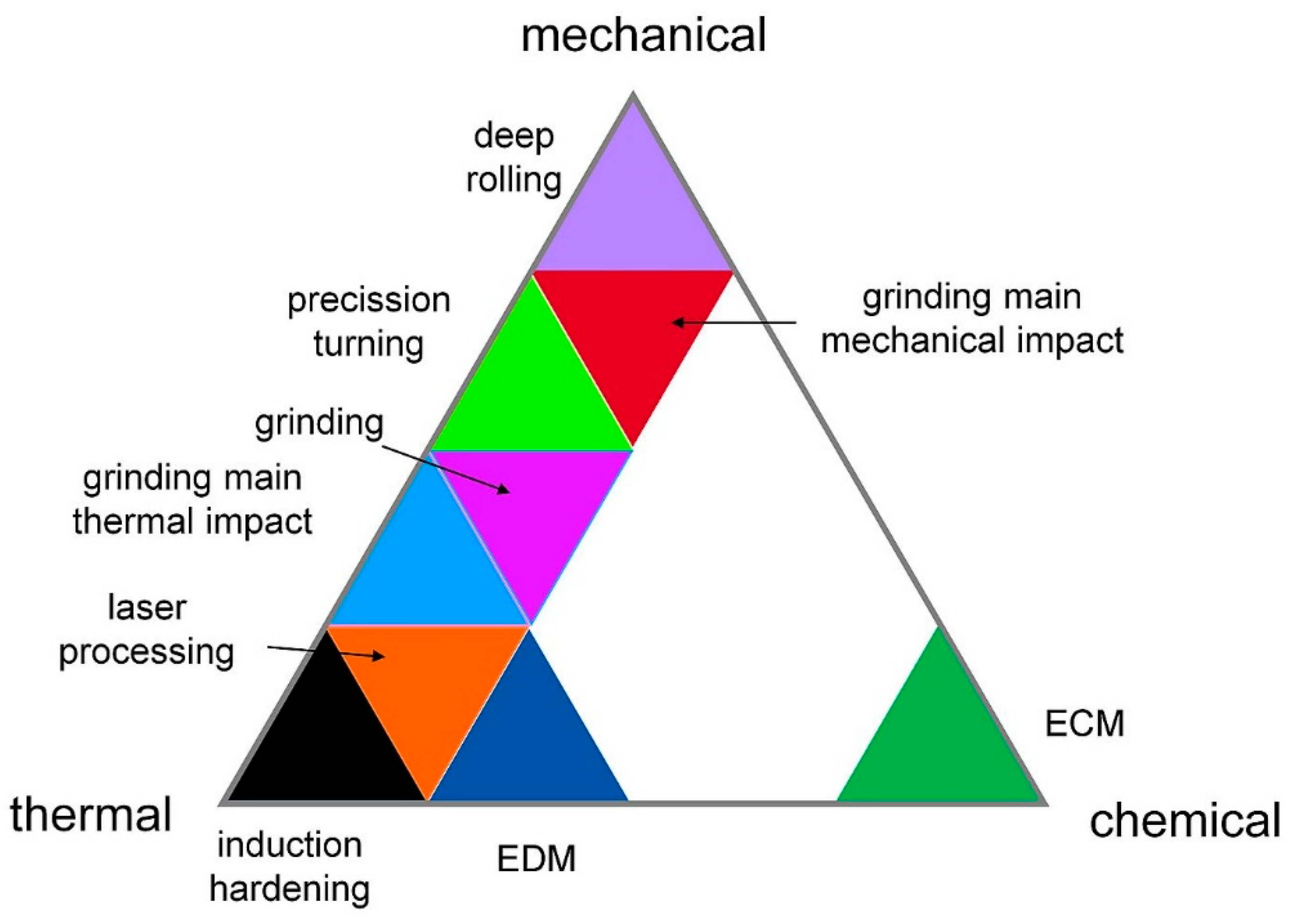
:1. Introduction
2. Materials and Methods
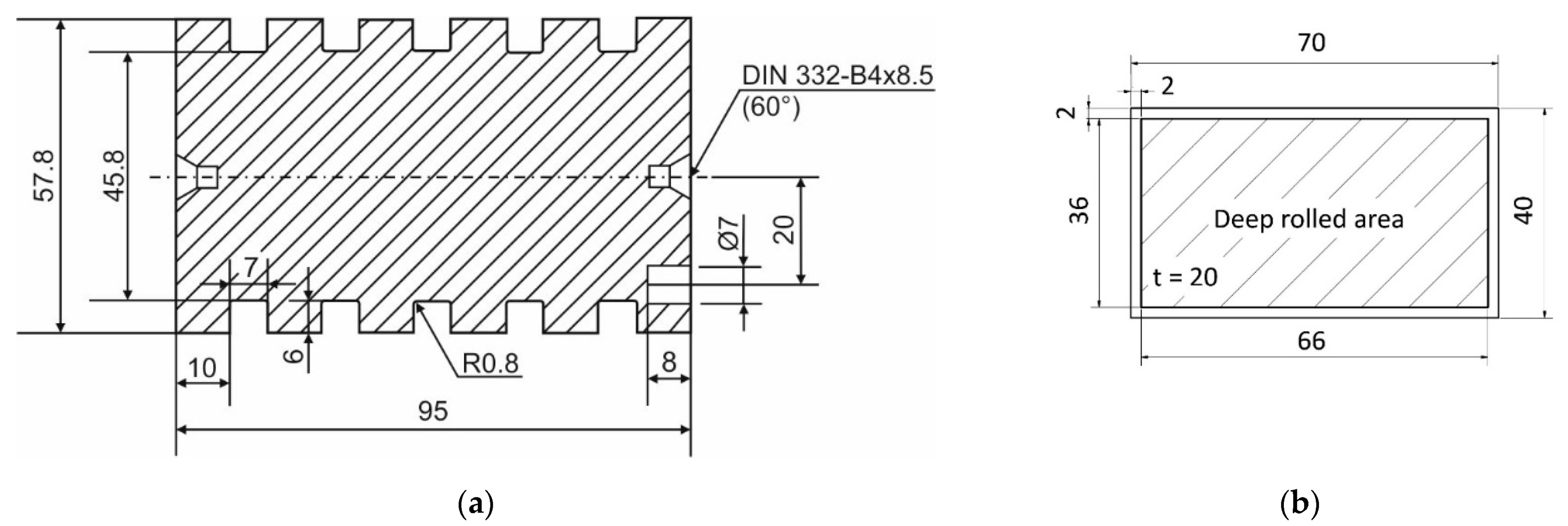
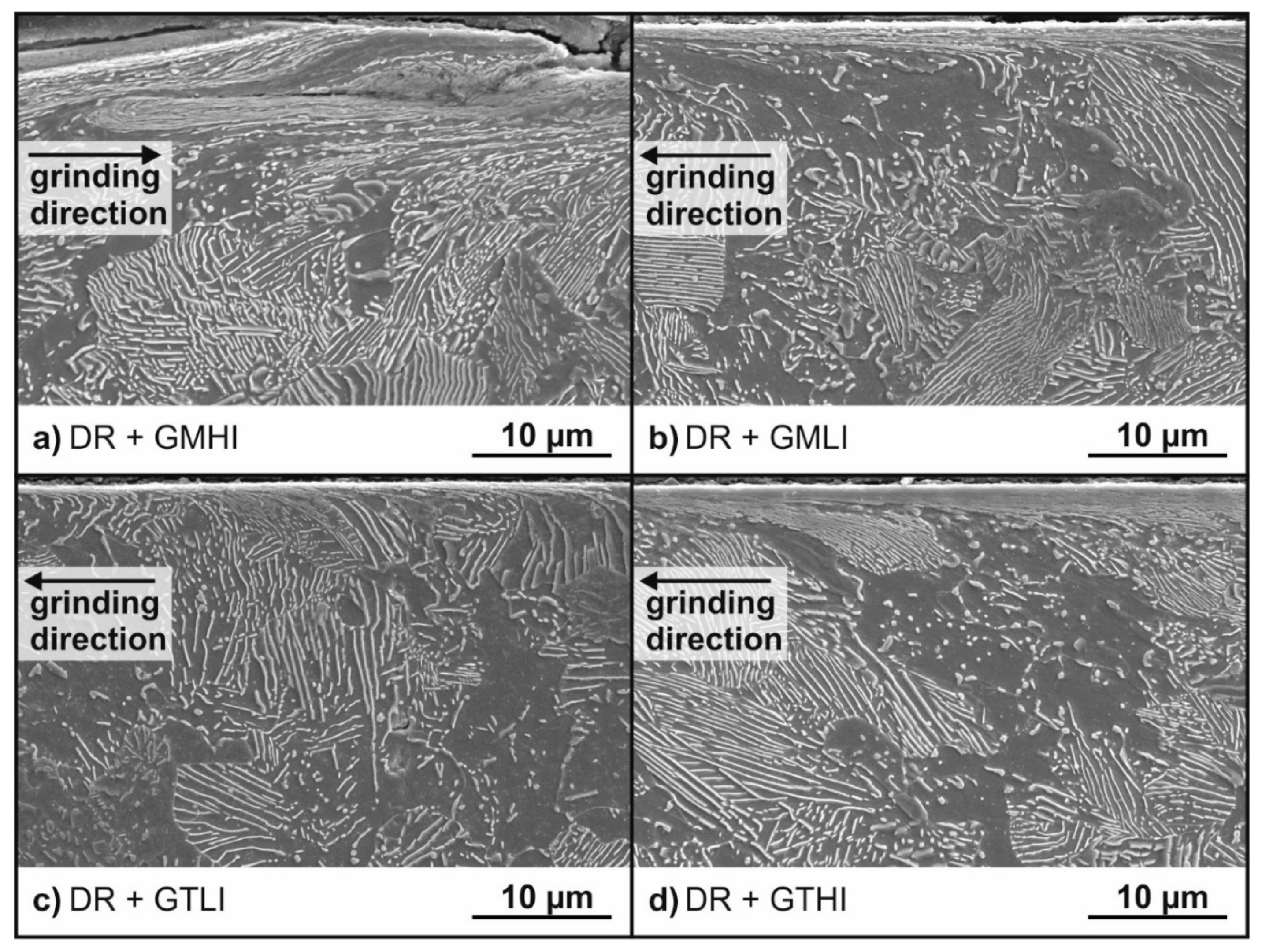
2.1. Deep Rolling
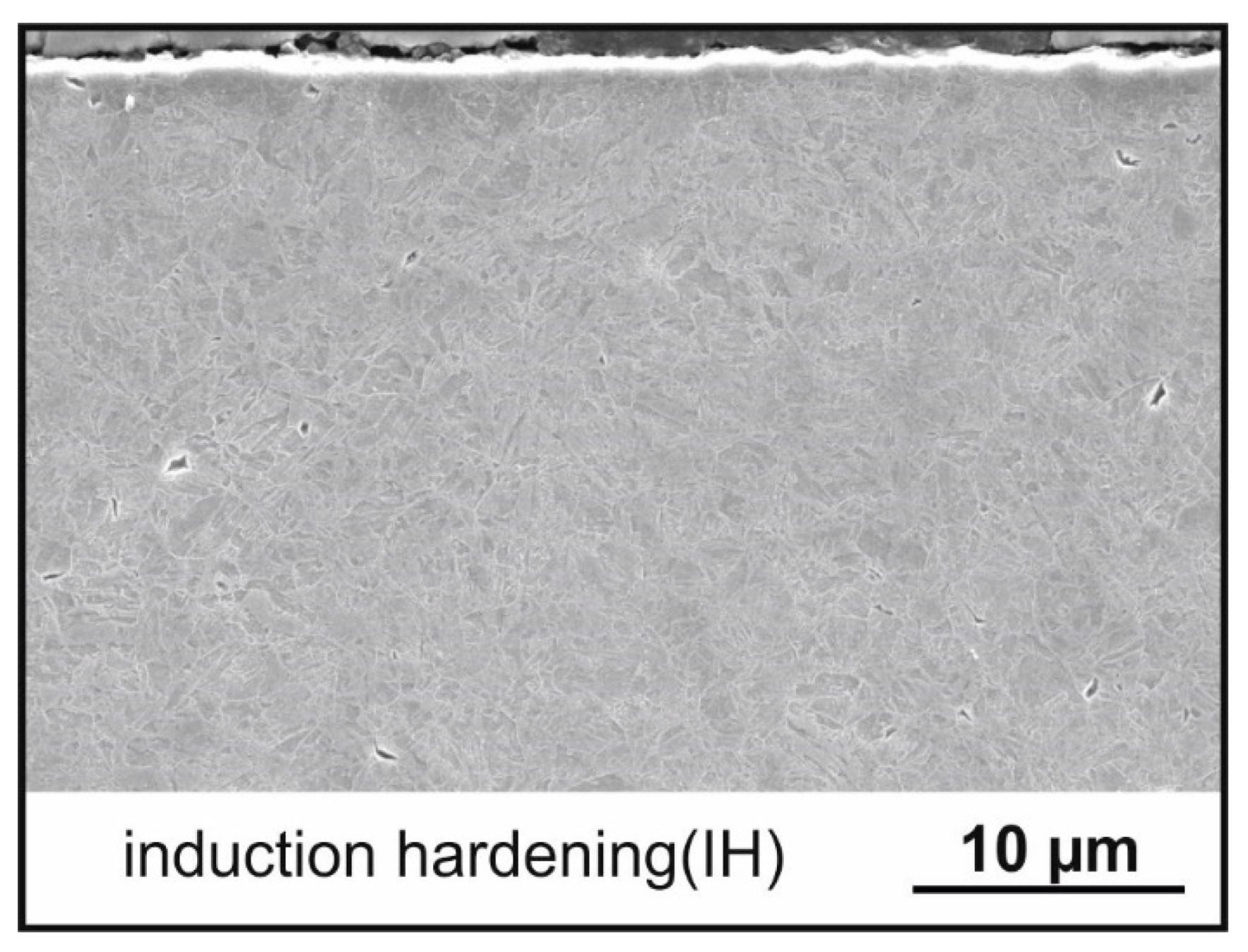
2.2. Induction Hardening
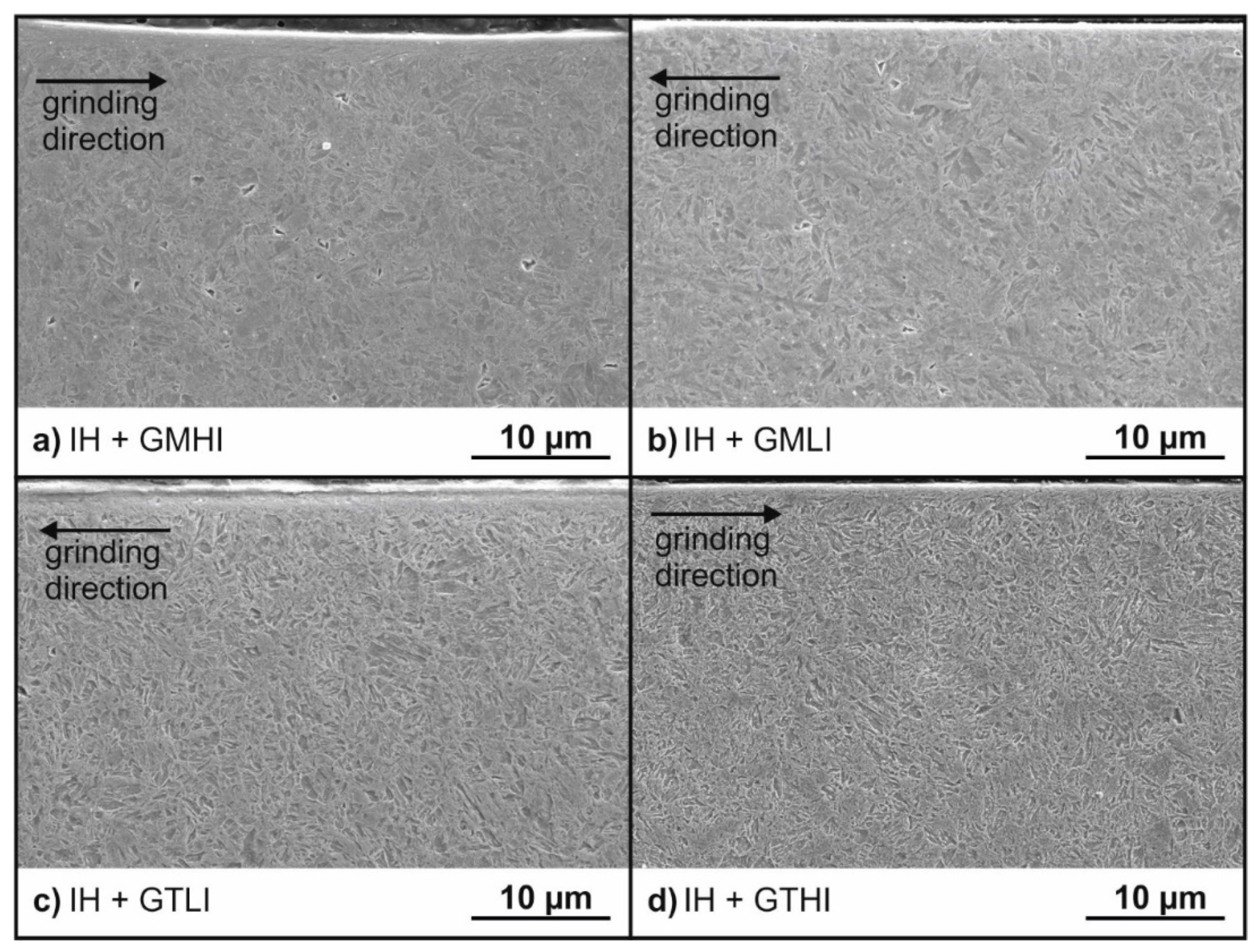
2.3. Grinding
2.4. Precision Turning
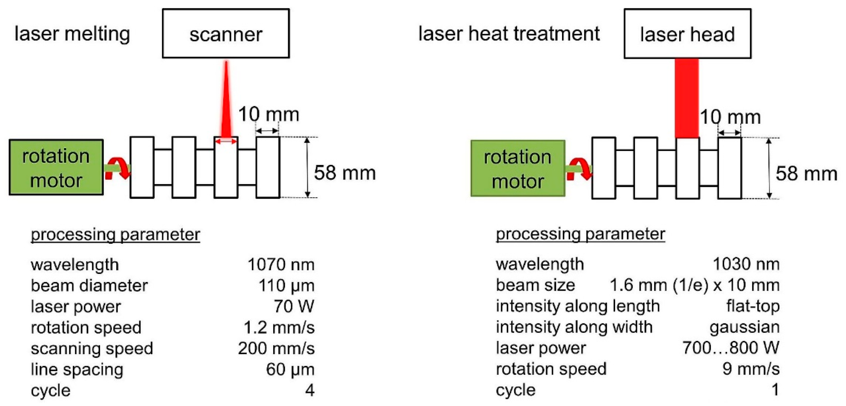
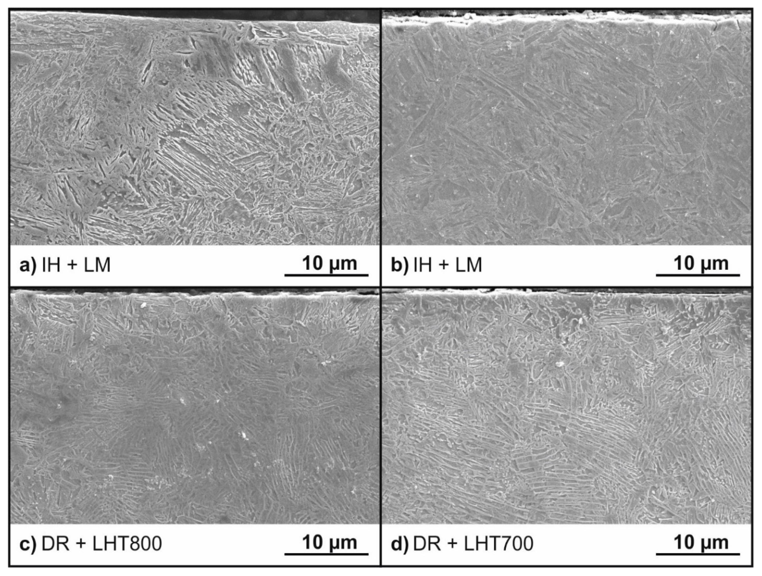
2.5. Laser Processing
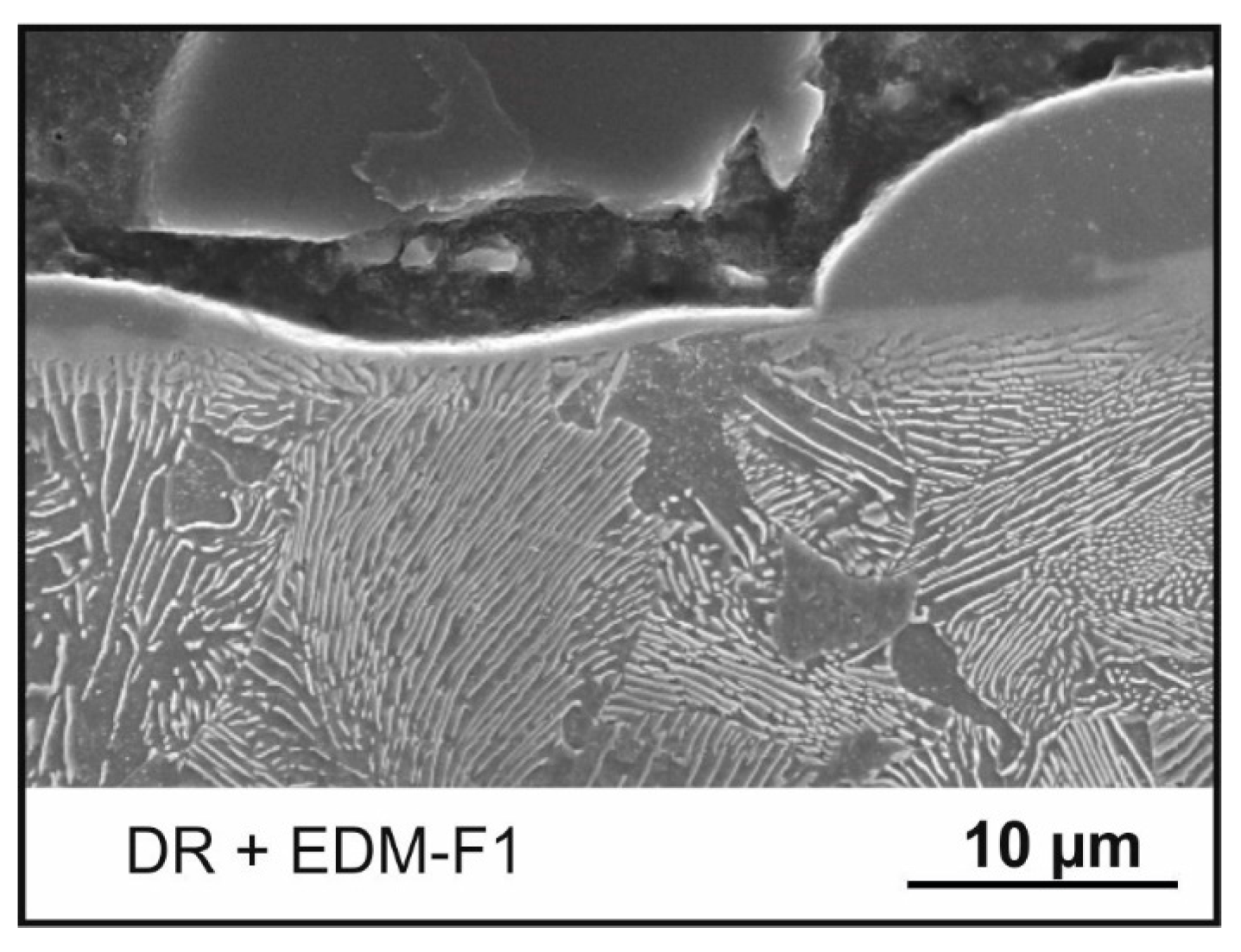
2.6. Electro-Discharge Machining (EDM)
2.7. Electro-Chemical Machining (ECM)
2.8. Analyzing Techniques
2.8.1. Hardness Measurements
2.8.2. Scanning Electron Microscopy (SEM), Energy-Dispersive X-Ray Spectroscopy (EDS) and Electron Backscatter Diffraction (EBSD) Measurements
2.8.3. X-ray Diffraction
3. Results
3.1. Comparison of Hardness Measurement Investigations Results
3.2. Comparison of Results Achieved with Electron Microscopy
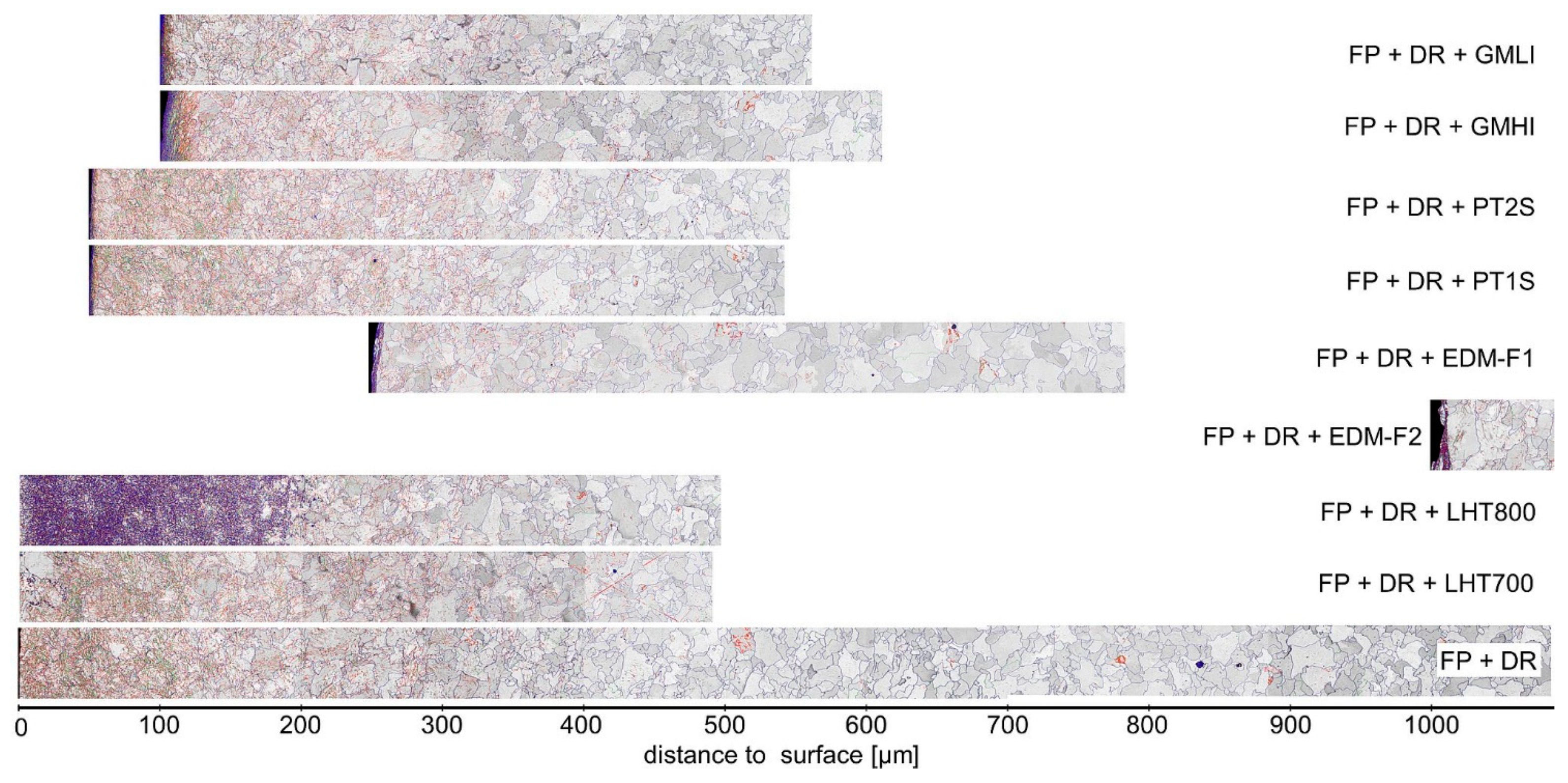
3.2.1. Overview of the Outer Layers
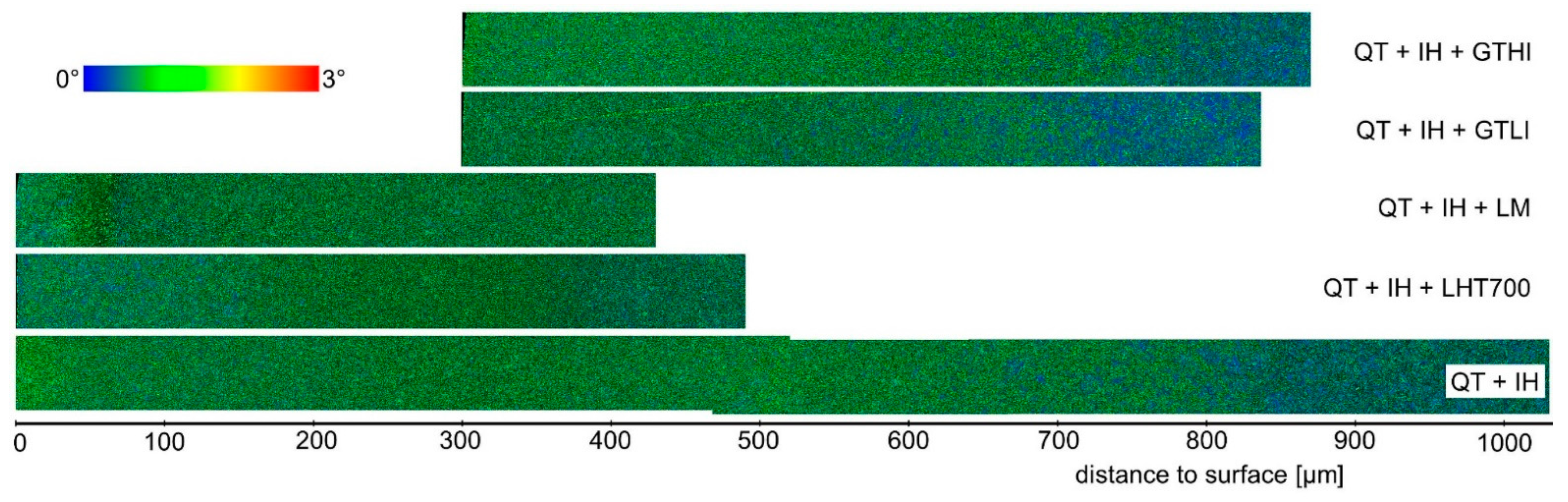
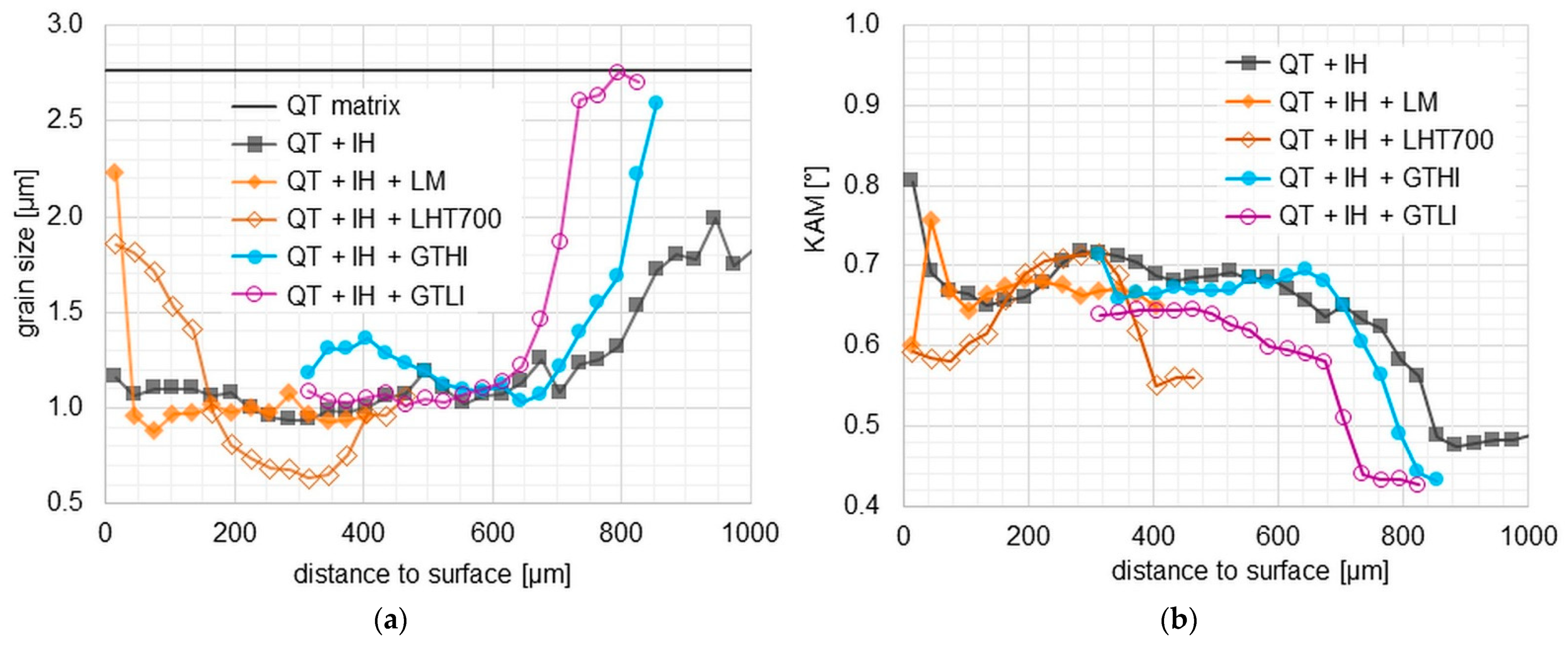
3.2.2. Investigations Using Electron Backscatter Diffraction
3.3. Comparison of XRD-Measurement Results
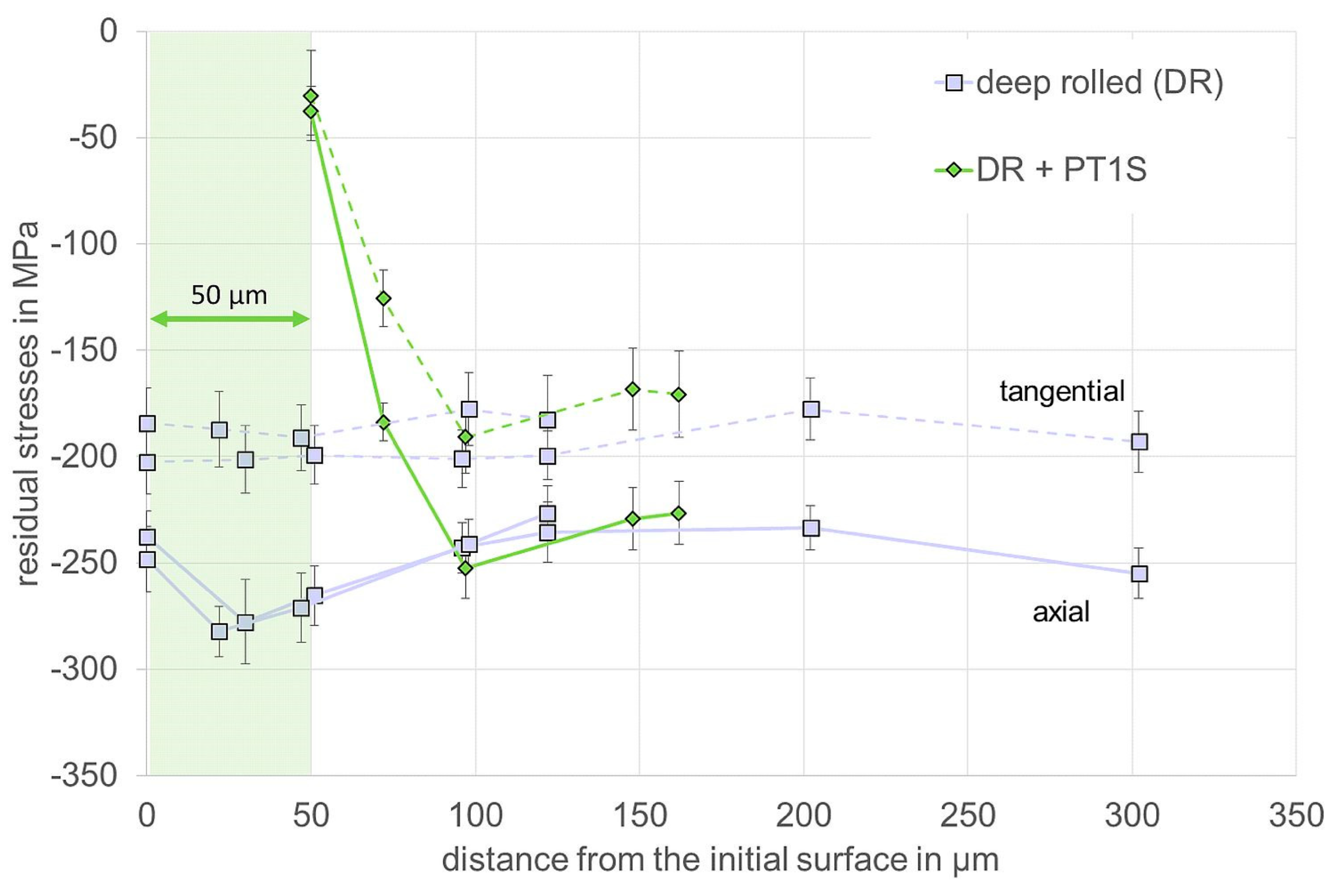
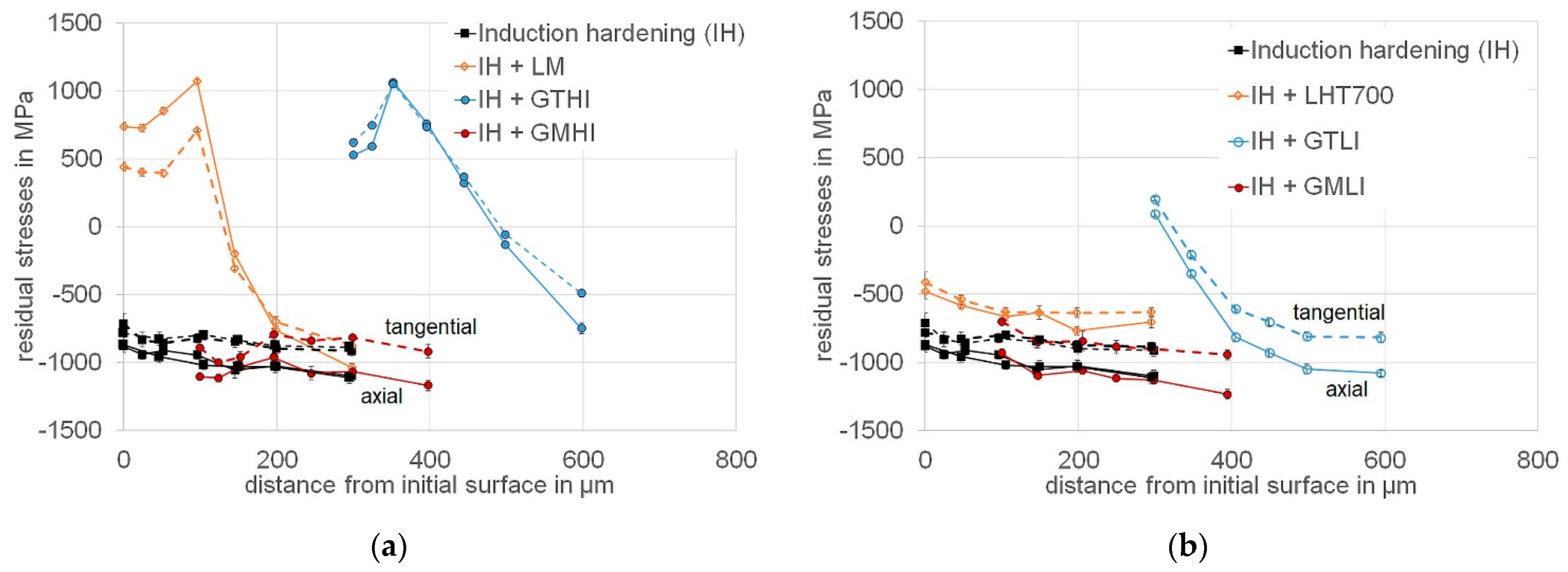
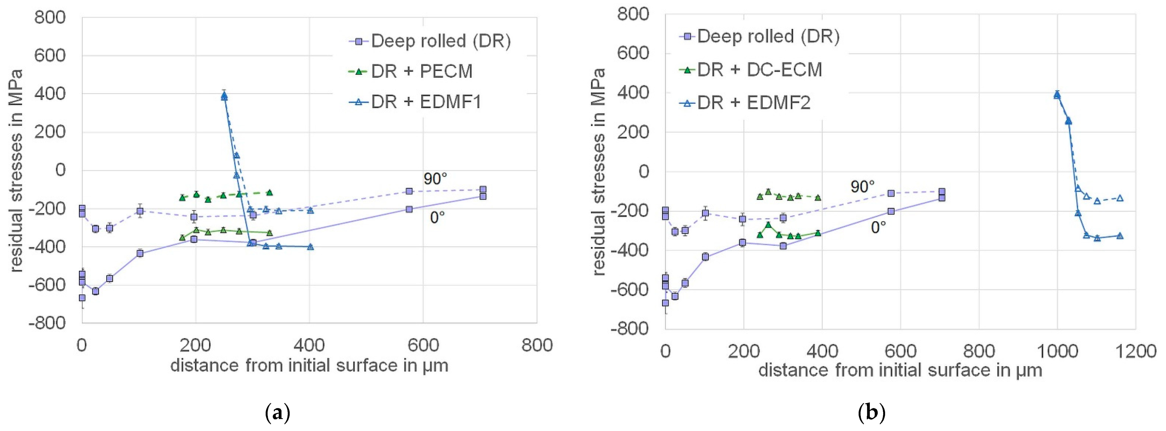
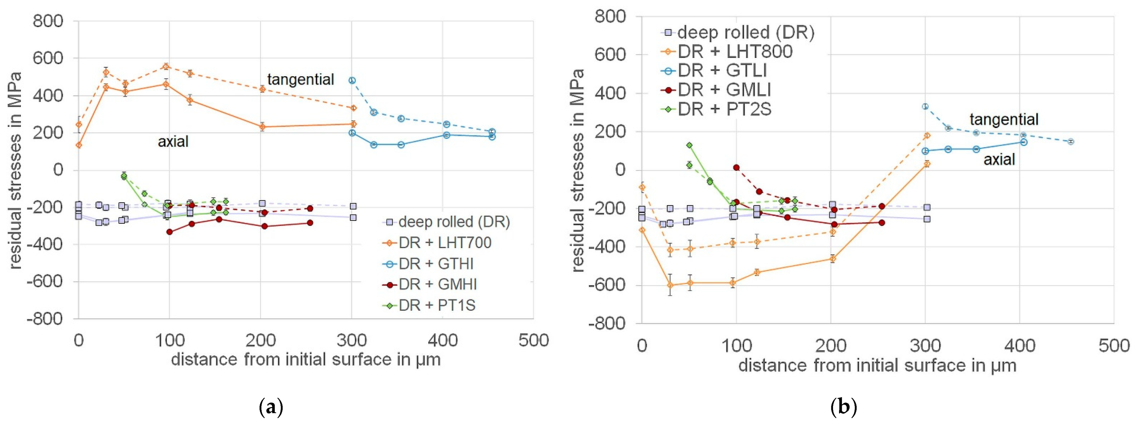
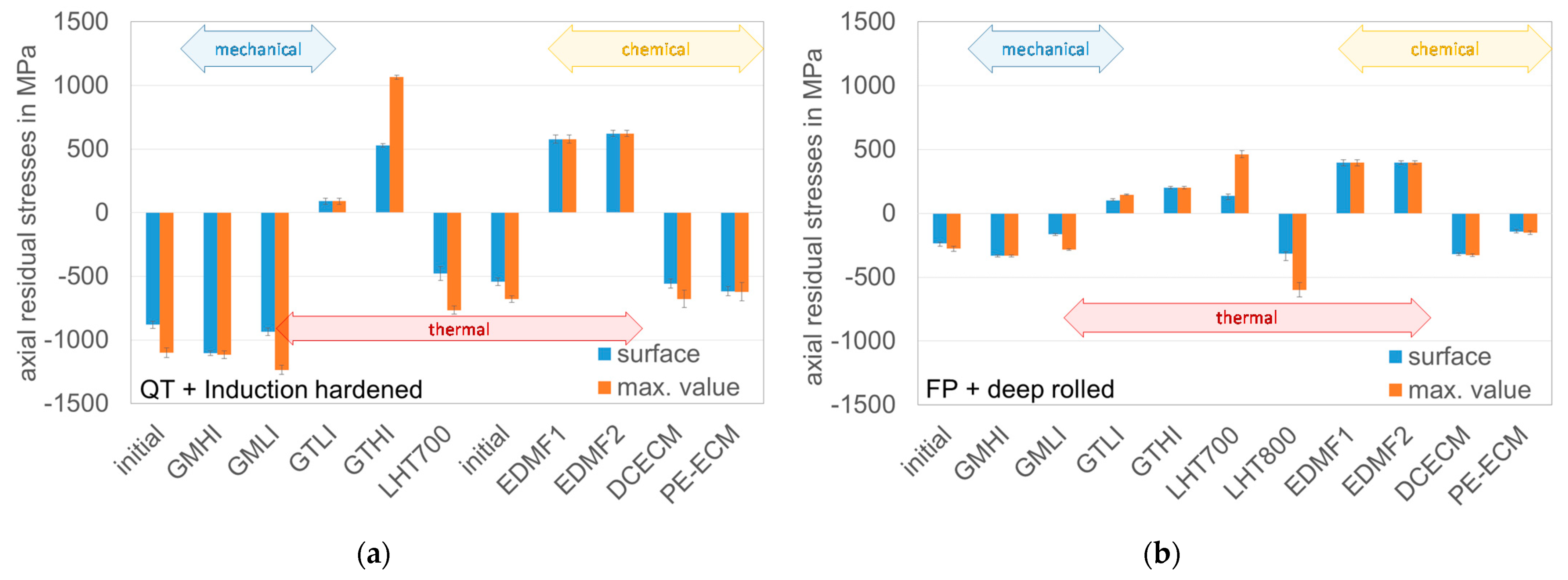
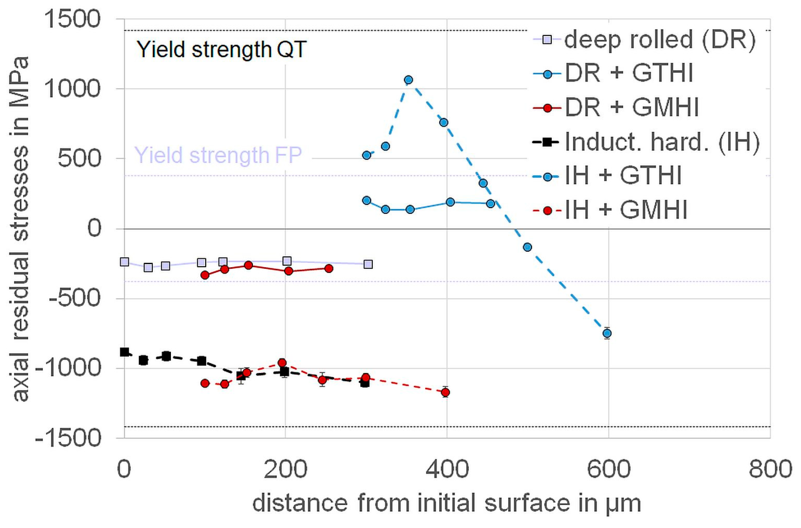
3.3.1. Residual Stresses
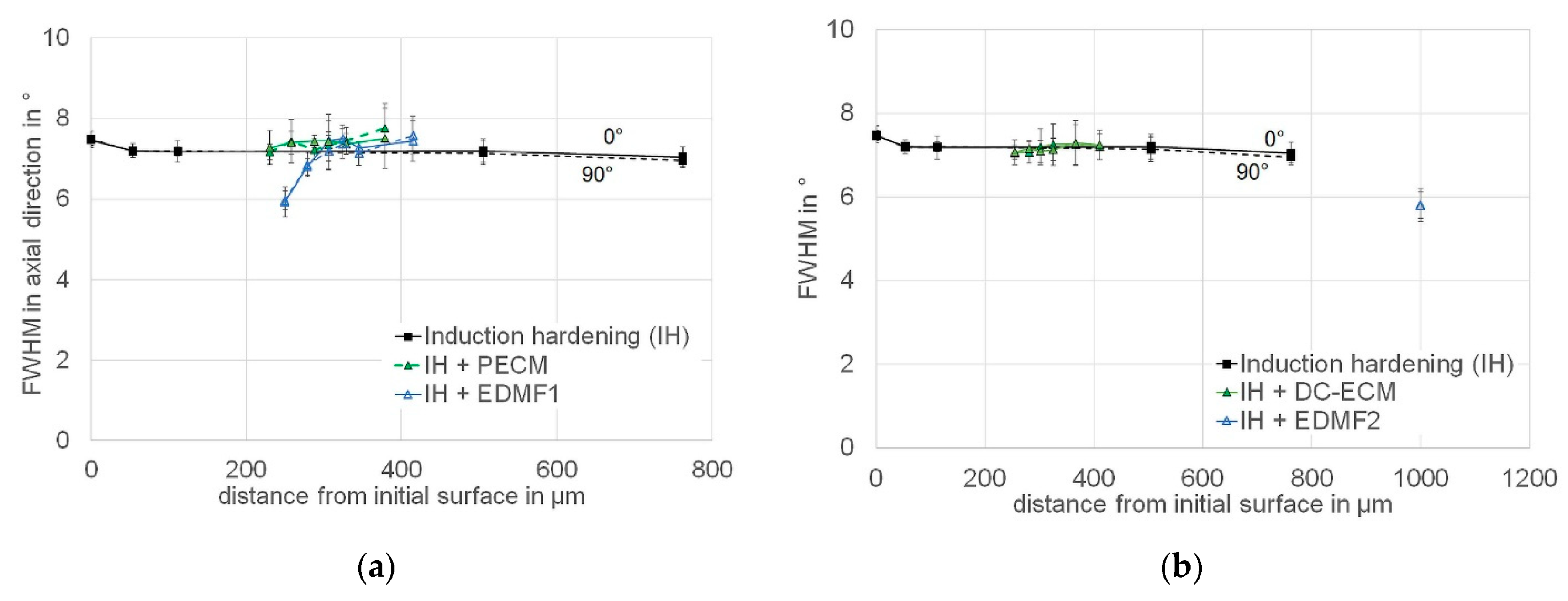
3.3.2. Full Width at Half Maximum (FWHM)
4. Discussion
4.1. Grinding
4.2. Precision Turning
4.3. Laser Hardening and Melting
4.4. EDM
4.5. ECM
4.6. Overall Process Comparison, Reliability of Measurement Results, and Influence of the Initial State
5. Conclusions
Author Contributions
Funding
Data Availability Statement
Acknowledgments
Conflicts of Interest
References
- Jawahir, I.S.; Brinksmeier, E.; M’Saoubi, R.; Aspinwall, D.K.; Outeiro, J.C.; Meyer, D.; Umbrello, D.; Jayal, A.D. Surface integrity in material removal processes: Recent advances. CIRP Annals Manuf. Technol. 2011, 60, 603–626. [Google Scholar] [CrossRef]
- Field, M.; Koster, W. Optimizing grinding parameters to combine high productivity with high surface integrity. CIRP Ann Manuf. Technol. 1978, 27, 523–526. [Google Scholar]
- Gerstenmeyer, M.; Hartmann, J.; Zanger, F.; Schulze, V. Adjustment of Lifetime-Increasing Surface Layer States by Complematary Machining. HTM J. Heat Treat. Mater. 2019, 74, 181–190. [Google Scholar] [CrossRef]
- Brinksmeier, E.; Meyer, D.; Heinzel, C.; Lübben, T.; Sölter, J.; Langenhorst, L.; Frerichs, F.; Kämmler, J.; Kohls, E.; Kuschel, S. Process Signatures—The Missing Link to Predict Surface Integrity in Machining. Proc. CIRP 2018, 71, 3–10. [Google Scholar] [CrossRef]
- Liao, Z.; La Monaca, A.; Murray, J.; Speidel, A.; Ushmaev, D.; Clare, A.; Axinte, D.; M’Saoubi, R. Surface integrity in metal machining—Part I: Fundamentals of surface characteristics and formation mechanisms. Int. J. Mach. Tools Manuf. 2021, 162, 103687. [Google Scholar] [CrossRef]
- La Monaca, A.; Murray, J.; Liao, Z.; Speidel, A.; Robles-Linares, J.; Axinte, D.; Hardy, M.; Clare, A. Surface integrity in metal machining—Part II: Functional performance. Int. J. Mach. Tools Manuf. 2021, 164, 103718. [Google Scholar] [CrossRef]
- Borchers, F.; Clausen, B.; Eckert, S.; Ehle, L.; Epp, J.; Harst, S.; Hettig, M.; Klink, A.; Kohls, E.; Meyer, H.; et al. Comparison of Different Manufacturing Processes of AISI 4140, Steel with Regard to Surface Modification and Its Influencing Depth. Metals 2020, 10, 895. [Google Scholar] [CrossRef]
- Meyer, H.; Epp, J.; Zoch, H.-W. Residual stress and dislocation density development in single track deep rolled AISI 4140H steel. Proc. CIRP 2018, 71, 192–197. [Google Scholar] [CrossRef]
- Gräbner, D.; Zielinski, T.; Vovk, A.; Riemer, O.; Lang, W. An Investigation on High-Resolution Temperature Measurement in Precision Fly-Cutting. Sensors 2021, 21, 1530. [Google Scholar] [CrossRef] [PubMed]
- Zielinski, T.; Vovk, A.; Riemer, O.; Karpuschewski, B. An Investigation on Internal Material Loads and Modifications in Precision Turning of Steel 42CrMo4. Micromachines 2021, 12, 526. [Google Scholar] [CrossRef] [PubMed]
- Frerichs, F.; Lübben, T. Influence of initial microstructure on manufacturing processes with thermal loads accompanied by hardening. Procedia CIRP 2020, 87, 521. [Google Scholar] [CrossRef]
- Frerichs, F.; Meyer, H.; Strunk, R.; Kolkwitz, B.; Epp, J. Development of a Process Signature for Manufacturing Processes with Thermal Loads. Metal Mat. Trans A 2018, 8, 3419. [Google Scholar] [CrossRef]
- Bergs, T.; Rommes, B.; Kohls, E.; Meyer, H.; Klink, A.; Heidemanns, L.; Harst, S. Experimental Investigation concerning the Influence of Electrochemical Machining on Process Chain induced Residual Stress States. Procedia CIRP 2020, 95, 726–730. [Google Scholar] [CrossRef]
- Klink, A. Process Signatures of EDM and ECM Processes—Overview from Part Functionality and Surface Modification Point of View. Procedia CIRP 2016, 42, 240. [Google Scholar] [CrossRef]
- Frerichs, F.; Lu, Y.; Lübben, T.; Radel, T. Process Signature for Laser hardening. Metals 2021, 11, 465. [Google Scholar] [CrossRef]
- Ehle, L.C.; Spille, J.; Meyer, H.; Kämmler, J.; Werner, J.; Schwedt, A.; Weirich, T.; Mayer, J. Sequential deep rolling and liquid nitrogen cooling for controlled twinning and martensitic transformation in metastable AISI D3 (X210Cr12) steel. Mater. Today Commun. 2021, 28. [Google Scholar] [CrossRef]
- Röttger, K. Walzen Hartgedrehter Oberflächen. Ph.D. Thesis, RWTH Aachen, Aachen, Germany, 2003. [Google Scholar]
- DIN EN ISO 6507. Metallic Materials—Vickers Hardness Test—Part 1: Test Method (ISO 6507-1:2018), German version EN ISO 6507-1:2018; Beuth Verlag: Berlin, Germany, 2018. [Google Scholar]
- DIN EN ISO 14577-1:2015-11. Metallic Materials—Instrumented Indentation Test for Hardness and Materials Parameters—Part 1: Test Method (ISO 14577-1:2015), German version EN ISO 14577-1:2015; Beuth Verlag: Berlin, Germany, 2015. [Google Scholar]
- Noyan, I.C.; Cohen, J.B. Residual Stress: Measurement by Diffraction and Interpretation; Springer: Berlin/Göttingen/Heidelberg, Germany, 2013. [Google Scholar]
- Nikitin, I.; Scholtes, B.; Maier, H.-J.; Altenberger, I. High temperature fatigue behavior and residual stress stability of laser-shock peened and deep rolled austenitic steel AISI 304. Scr. Mater. 2004, 50, 1345–1350. [Google Scholar] [CrossRef]
- Temmler, A.; Liu, D.; Preußner, J.; Oeser, S.; Luo, J.; Poprawe, R.; Schleifenbaum, J.H. Influence of laser polishing on surface roughness and microstructural properties of the remelted surface boundary layer of tool steel H11. Mater. Des. 2020, 192, 108689. [Google Scholar] [CrossRef]


| Notation Unit | C % | Cr % | Mn % | P % | S % | Si % | Mo % | Ni % | Al % | Cu % |
|---|---|---|---|---|---|---|---|---|---|---|
| AISI 4140/42CrMo4 | 0.448 | 1.09 | 0.735 | 0.012 | 0.002 | 0.264 | 0.244 | 0.200 | 0.018 | 0.065 |
| DIN EN ISO 683-2 | 0.38–0.45 | 0.90–1.20 | 0.60–0.90 | max. 0.025 | max. 0.010 | max. 0.40 | 0.15–1.30 | – | – | – |
| Notation | Initial Material Condition | |
|---|---|---|
| FP | QT | |
| yield strength (YS) | 380 MPa (YSFP) | 1420 MPa (YSQT) |
| ultimate tensile strength (UTS) | 730 MPa (UTSFP) | 1560 MPa (UTSQT) |
| Ball Diameter db [mm] | Deep Rolling Pressure pdr [bar] | Deep Rolling Force Fdr [N] | Feed fdr [mm/rev] | Deep Rolling Velocity vdr [mm/min] |
|---|---|---|---|---|
| 13 | 159 | 2107 | 0.04 | 100 (cylinders) 0.75 (cuboids) |
| Workpiece | Inductor Size S [mm] | Feed vft [mm/s] | Maximal Generator Current Imax [A] | Frequency f [kHz] |
|---|---|---|---|---|
| cuboid | 50 (length) | 900 | 478 | 10.8 |
| cylinder | 62 (inner dia.) | 500 | 194 | 180 |
| Level | Grinding Wheel | Cutting Speed vc (m/s) | Radial Feed Rate vfr (mm/min) | Depth of Cut ae (mm) | Direction | Depth of Dressing Cut ae,d (mm) |
|---|---|---|---|---|---|---|
| GMHI | A60P5AV | 1.36 | 0.20 | 0.1 | Down-grinding | 3 × 0.02 |
| GMLI | A60P5AV | 14.76 | 0.20 | 0.1 | Down-grinding | 3 × 0.02 |
| GTLI | A80CC5V | 35.18 | 2.45 | 0.3 | Up-grinding | 5 × 0.02 |
| GTHI | A80CC5V | 35.18 | 4.90 | 0.3 | Up-grinding | 5 × 0.02 |
| Level | Cutting Speed vc [m/min] | Feed f [µm/rev] | 1. Depth of Cut ap,1 [µm] | 2. Depth of Cut ap,2 [µm] |
|---|---|---|---|---|
| PT1S | 100 | 18 | 50 | 0 |
| PT2S | 100 | 18 | 30 | 20 |
| Level | Input State | 1st Process | 2nd Process | Laser Power [W] | Focus Diam. [µm] | Scan Velocity [mm/s] | Line Spacing [µm] | Rot. Speed [mm/s] | Overrun Cycles [–] |
|---|---|---|---|---|---|---|---|---|---|
| LM | QT | Inductive hardening | Laser melting | 70 | 110 | 200 | 60 | 1.2 | 4 |
| Level | Initial State | 1st Process | 2nd Process | Laser Power [W] | Rot. Speed [mm/s] | Beam Size [mm2] | Overrun Cycles [–] | Surface Temperatur [°C] |
|---|---|---|---|---|---|---|---|---|
| LHT700 | QT | Inductive hardening | Laser hardening | 700 | 9 | 10 × 1.5 | 1 | 1250 |
| LHT700 | FP | Deep rolling | Laser hardening | 700 | 9 | 10 × 1.5 | 1 | 940 |
| LHT800 | FP | Deep rolling | Laser hardening | 800 | 9 | 10 × 1.5 | 1 | 1240 |
| Level | Open Circuit Voltage ûi [V] | Discharge Current ie [A] | Discharge Duration te [µs] | Pulse Interval Time t0 [µs] | Machining Depth z [µm] |
|---|---|---|---|---|---|
| EDM-F1 | 100 | 8 | 14.1 | 28.9 | 250 |
| EDM-F2 | 100 | 3.4 | 8.4 | 13.1 | 1000 |
| Level | Voltage U [V] | Feed Rate f [mm/min] | Pulse Duration tp [µs] | Pause Duration t0 [µs] | Inlet Pressure P [bar] |
|---|---|---|---|---|---|
| DC-ECM | 15 | 0.5 | – | – | 2 |
| PECM | 25 | 0.075 | 1000 | 1000 | 4 |
| Parameter Abbr. [unit] | Primary Beam Diameter db [mm] | Lattice Plane | Tube Voltage U [kV] | Tube Current I [mA] | Ψ Angles 11 between | Step [°2θ] | Range [°2θ] |
|---|---|---|---|---|---|---|---|
| value | 2 | α{211} | 33 | 40 | −45° to +45° | 0.1 | 147 to 163 |
Publisher’s Note: MDPI stays neutral with regard to jurisdictional claims in published maps and institutional affiliations. |
© 2021 by the authors. Licensee MDPI, Basel, Switzerland. This article is an open access article distributed under the terms and conditions of the Creative Commons Attribution (CC BY) license (https://creativecommons.org/licenses/by/4.0/).
Share and Cite
Borchers, F.; Clausen, B.; Ehle, L.C.; Eich, M.; Epp, J.; Frerichs, F.; Hettig, M.; Klink, A.; Kohls, E.; Lu, Y.; et al. The Influence of Former Process Steps on Changes in Hardness, Lattice and Micro Structure of AISI 4140 Due to Manufacturing Processes. Metals 2021, 11, 1102. https://doi.org/10.3390/met11071102
Borchers F, Clausen B, Ehle LC, Eich M, Epp J, Frerichs F, Hettig M, Klink A, Kohls E, Lu Y, et al. The Influence of Former Process Steps on Changes in Hardness, Lattice and Micro Structure of AISI 4140 Due to Manufacturing Processes. Metals. 2021; 11(7):1102. https://doi.org/10.3390/met11071102
Chicago/Turabian StyleBorchers, Florian, Brigitte Clausen, Lisa C. Ehle, Marco Eich, Jérémy Epp, Friedhelm Frerichs, Matthias Hettig, Andreas Klink, Ewald Kohls, Yang Lu, and et al. 2021. "The Influence of Former Process Steps on Changes in Hardness, Lattice and Micro Structure of AISI 4140 Due to Manufacturing Processes" Metals 11, no. 7: 1102. https://doi.org/10.3390/met11071102