Article

Introducing Compressive Residual Stresses into a Stainless-Steel T-Pipe Joint by an Overlay Weld

1
School of Chemical Engineering and Technology, Tianjin University, Tianjin 300350, China
2
Nuclear and Radiation Safety Center, Beijing 100035, China
3
State Key Laboratory of Nuclear Power Safety Monitoring Technology and Equipment, Shenzhen 518172, China
4
China Nuclear Power Engineering Co., Ltd., Shenzhen 518172, China
*
Author to whom correspondence should be addressed.
Metals 2021, 11(7), 1109; https://doi.org/10.3390/met11071109
Submission received: 2 June 2021 / Revised: 1 July 2021 / Accepted: 2 July 2021 / Published: 12 July 2021

Abstract

:
Microcracks are always present in the deposited metal of nickel-based alloys and austenitic stainless steels, which affects the safety of the pressure pipes. If compressive stress can be introduced into the cracked position by overlay welding, the time required with ordinary gouging repair welding technology will be significantly reduced, which is practical significance for pressure pipes repair welding. In this work, a stainless-steel T-pipe joint was fabricated using manual metal arc welding with an ER316L wire, and an overlay weld was fabricated using tungsten inert gas arc welding with an ERNiCrFe-7A wire. The overlay thickness was about 10 mm. The contour method was employed to measure the residual stress in the T-pipe joint. The results show that compressive residual stress about 50 MPa is formed in the original ER316L weld, which proves that the residual compressive stress can be obtained in the original weld by surfacing 10 mm thick nickel base alloy on the original weld surface.

1. Introduction

Ductility-dip cracking (DDC) is a type of solid-state cracking that occurs in a number of engineering materials with austenitic crystal lattice, such as austenitic stainless steel and nickel alloys. During welding, the heat-affected zone or weld is heated to a susceptible temperature range of about 800–1500 °C; under these conditions, high-localized strain initiates grain boundary sliding, precipitated intergranular carbides increase the stress concentration, and impurity elements segregated at the grain boundary render the boundary weaker, thus DDC forms [1,2,3]. Being a type of microcrack, DDCs are difficult to find via penetration tests in post-weld examinations; however, they turn into macrocracks through propagation during working. Thus, repair welding is always employed to eliminate potential damage because it can meet the strict time constraints of plants shutdown and economic requirements.
The ordinary repair welding procedure consists of first gouging out the cracked parts and then filling the gouge with welding. Since the repair weld is often narrow and short, a high-level constraint is usually introduced into it, and residual stress in repair welding will exhibit clear three-dimensional features [4]; most repair welds in steam chests, piping, and headers are prone to cracking [5]. In order to eliminate crack danger and increase the quality of repair welding, many techniques have been developed, such as the half-bead technique, temper-bead technique, and pre-weld and post-weld heat treatments [6,7,8]. These techniques can provide metallurgical benefits to the repair welding procedure, but residual stress should be considered at the same time, as it can become relatively high with high constraints. The distribution of residual stress in repair welding is related to the length of the repair weld, the constraints of the structure, the formation of a welded joint, and the dimensions of the joint; however, high tensile stress is always present in the welded zone, and compressive stress will form in the region at a large distance from the weld [9,10,11,12]. If the original crack is not gouged out and its front is located in the tension stress zone, the crack will propagate [13]. By contrast, if the front of the crack is located in the compressive stress zone, a closure behavior will be observed [14]. This phenomenon makes it possible to replace gouged-out repair welds with overlay welds.
In order to ascertain the residual stress distribution of welded joint, many measurement methods are used currently, such as X-ray diffraction, ultrasonic diffraction, neutron diffraction, drilling, and indentation [14]. Furthermore, there exists the cutting method, contour method, and other more destructive methods. X-ray diffraction, drilling, and the indentation method are used to explore an area close to the sample surface. When it is necessary to measure the residual stress distribution in the sample section, neutron diffraction and the contour method represent effective approaches. Owing to its simple operation, the contour method has been widely adopted [14].
The contour method was established in 2000. It is based on Bueckner’s elastic superposition principle, shown in Figure 1. The method is widely used in the measurement of residual stress in specimens.
When the specimen is cut along a certain direction in the measurement process, residual stress will be released in the cut section. The release result shows that the section exhibits a different displacement in the normal direction. After the displacement is measured, the normal residual stress in the cutting plane is calculated with the finite element method. The accuracy of the contour method is directly related to the cutting method, constraint method, contour measurement method, and displacement data processing method [15]. Using the low-speed wire electrical discharge machining (EDM) and a copper cutting wire with a radius of 0.1–0.25 μm, a satisfactory cutting surface can be obtained. The specimen should be firmly constrained during cutting and be as close as possible to the cut section [16]. Both the three-coordinates contact measuring machine and the optical non-contact profilometer can be used to obtain a release of the displacements, thus meeting the accuracy requirements [17]. During displacement data processing, the average value of the data on the two cutting surfaces should be taken to eliminate the influence of the cutting straightness and shear stress on the cutting surface. At the same time, the boundary measurement results and the points with obvious errors should be removed, and the spline surface and local average method should then be adopted to fit the displacement data. The elastic finite element method analysis is generally used for residual stress calculation [16,17,18,19]. Benefiting from the convenient measurement of the internal stress, the contour method has been used in many circumstances, including for welding residual stress testing of different materials and repair welding residual stress testing [20,21]. Furthermore, the measurement results are in good agreement with those of neutron diffraction, the hole drilling method, X-ray diffraction, and numerical simulations.
The research object of this paper is T-type pipe joint, which is a common joint in primary circuit of nuclear power plant. Its working temperature is 343 °C, working pressure is 17.13 MPa, and its material is Z2CND18.12N. TIG method is used for joint welding, and ER316L is used as welding wire. Due to the high restraint of T-joint and the hot cracking tendency of ER316L, several ER316L weld cracks were found in the maintenance. In order to shorten the maintenance time, it is proposed to use overlay welding method for repair welding.
Owing to the high restraint of the T-pipe joint, high tensile stress can be easily formed in the weld [12]. At the same time, the austenitic stainless-steel filling material is sensitive to hot cracking, and microcracks are formed in the weld after welding [22]. According to the research results obtained for thick structures, compressive stress can be generated in an area adjacent to a repair weld [9]. Saukkonen et al. [23] researched the residual stress distribution in the weld cross-section by a contour method, and the residual stress distribution is used to evaluate the EAC susceptibility of various areas of the pipe weld. Hicks et al. [24] evaluated the residual stresses induced by repairs to small diameter stainless steel pipe welds. The results show that repair welds markedly increase the magnitude of the tensile axial residual stresses for weld configurations. Therefore, a repair weld is conducive to residual compressive stress is introduced into the welded joint.
For the T-pipe joint, if compressive stress can be formed at the microcrack zone as a consequence of the shrinkage of the overlay weld, the crack can be closed, and the possibility of its expansion can be eliminated, resulting in a substantial time saving and economic advantage. In this work, nickel-based alloys were used for overlay repair welding outside the T-joint; additionally, in order to determine the effect of weld repairing, the residual stress in the joint was measured via the contour method. It is expected that this study would propel the application of the overlay weld in stainless-steel T-pipe joint repairing.

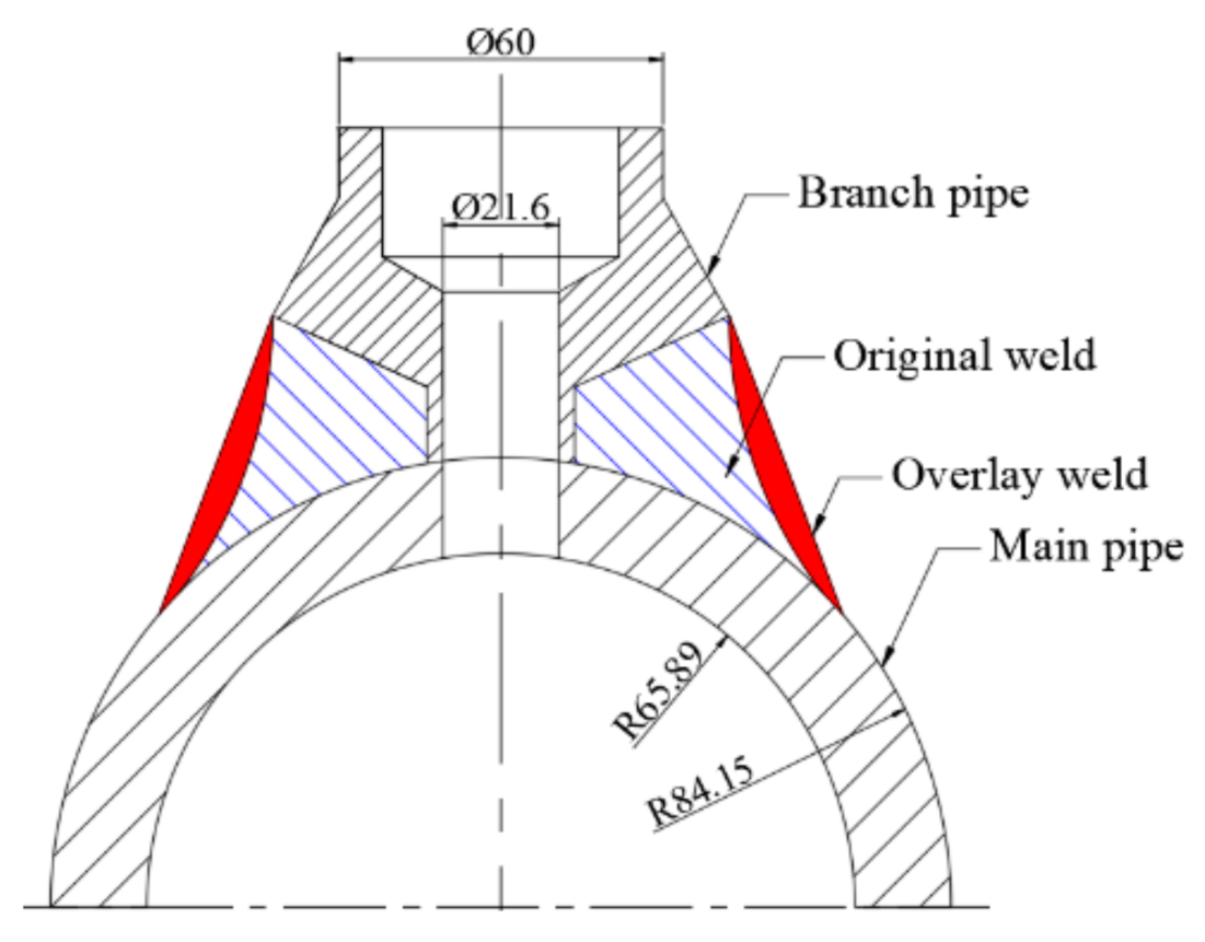
2. Materials, Geometry, and the Welding Process

Residual stress measurements were carried out on a test component manufactured from a Z2CND18.12N stainless-steel pipe and rod. The outside diameter, thickness, and length of the main pipe are 168.3, 18.26, and 335 mm, respectively. The branch pipe consists of a rod with a diameter of 60 mm; its internal bore diameter was machined to 21.6 mm after welding. The final component is shown in Figure 2.
The two pipes were solution heat treated (for 1 h at 1050 °C followed by air cooling) to remove any residual stress remaining from the original fabrication. The main pipe and branch pipe were mounted together and welded with the manual metal arc (MMA) method using an ER316L filling wire with a diameter of 3.2 mm. Stress-relieving heat treatment (for 0.5 h at 650 °C followed by air cooling) was conducted on the T-pipe joint to eliminate the welding stress. Subsequently, overlay welding was carried out using tungsten inert gas (TIG) with an automatic pipe welding machine, and a 0.9-mm ERNiCrFe-7A (690 nickel-based alloy) welding wire was adopted. The test component dimensions were shown in Table 1 and welding parameters were shown in Table 2. These welding parameters are the best welding parameters optimized by experiments. The T-joint was fixed to the worktable, and the welding track of the automatic welding was arranged to be on the upper part of the branch pipe. The overlay weld reached a final thickness of 10 mm and was examined via macro metallography, as shown in Figure 3. Two T-joints were fabricated.
ER316L and ERNiCrFe-7A is a commonly used welding material for nuclear power pipes. As both of them are austenitic matrix materials, their cold cracking resistance is good. However, they all have the tendency of hot cracking because they contain more alloy elements. The original weld of T-joint studied in this paper is ER316L material, and cracks occur. Therefore, ERNiCrFe-7A is selected as welding material in the process of welding. The welding process is carefully verified, and the heat input and interlayer temperature are reduced as much as possible to ensure that no new cracks will be produced during the overlay process.

3. Residual Stress Measurement
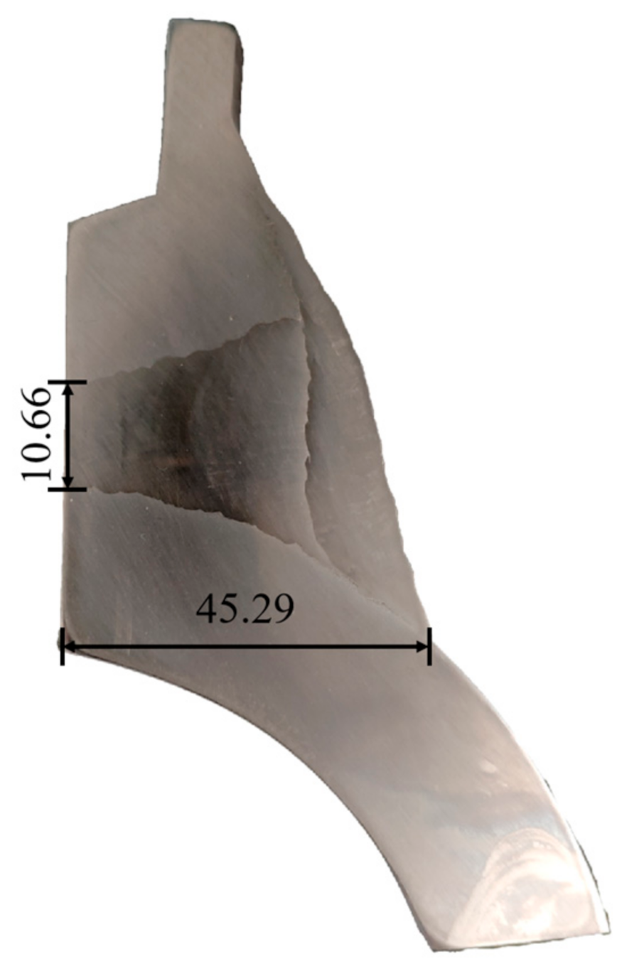
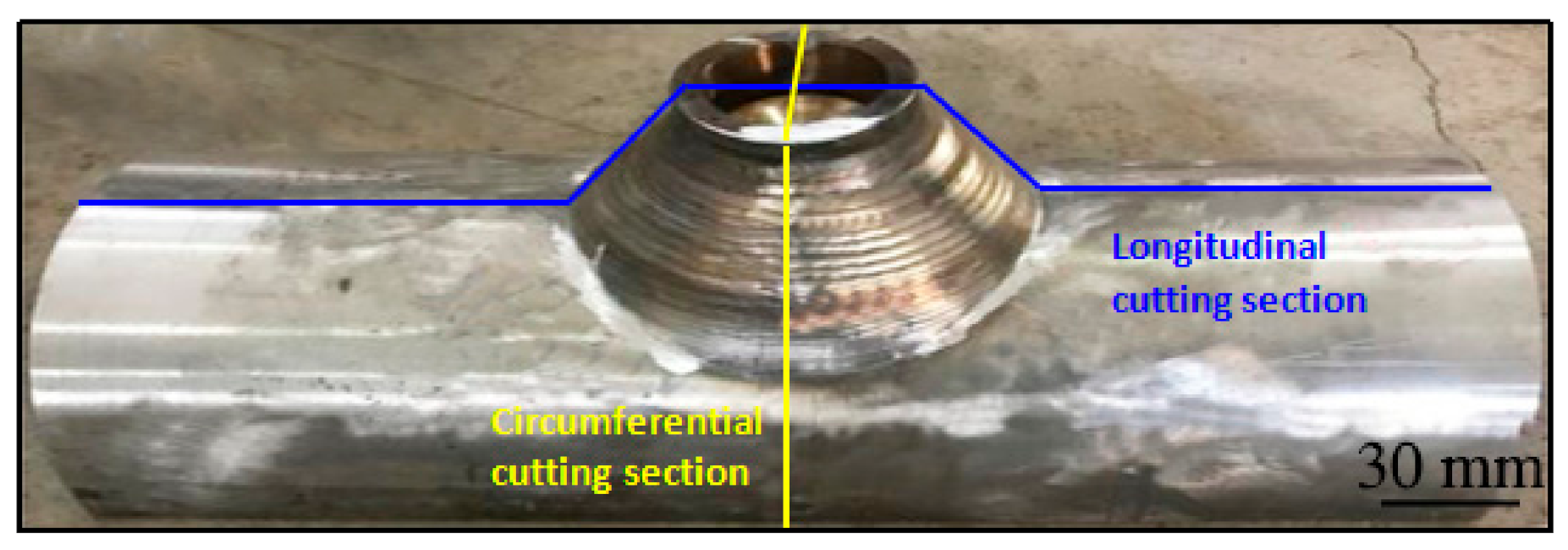
The contour method was used to measure the residual stress in the T-pipe joints; sections were cut along the longitudinal and circumferential directions, as shown in Figure 4. The measurement process involves cutting along the measuring surface, scanning the profile of the cut surface, smoothing the measurement data, and calculating the normal stress of the original cut surface with the finite element method.

3.1. Sample Cutting

Section cutting was conducted via EDM (Sanguang Technology Co., Ltd., Suzhou, China) using a 0.1-μm pure copper cutting wire at a speed of 0.1 mm/s, and the sample was cooled with deionized water. Due to the stress release during the cutting process, the sample deformation will affect the cutting accuracy and measurement accuracy; therefore, the clamping position was set to be as close as possible to the cutting position [16]. However, compared with the rigid constraint, the constraint effect of this type of clamping method is weaker. When the clamping is very reliable, cutting the most concerned position first can provide more reliable results. On the other hand, when the clamping constraint is weak, cutting the most concerned position at last can provide more reliable results [21]. The concerned sections of the T-joint were located in the middle of sample, and the cutting was conducted from one side to the other. The surfaces of the cut sections were all smooth, and no bulge phenomenon was observed at the edges.

3.2. Contour Scanning

After cutting, the sample surface was cleaned using an ultrasonic cleaner (Xinxin ultrasonic electronic equipment Co., Ltd., Jining, China) to remove oil and other impurities, and the sample was dried using an electric blower. The contour can be measured using contact, optical, or electromagnetic methods [17]; among these, the contact and optical measurement methods are the most widely used. In this work, a Steinbichler COMET L3D (Steinbichler Optotechnik Gmbh, Neubeuern, Germany) was used for the non-contact measurements; its measuring principle is based on blue light interference. The standard pattern was used for calibration before the measurements, and the distance between the measuring points was set to be less than 170 μm.

3.3. Stress Calculation

ABAQUS V6.10 (Dassault Systems, Paris, France) was used to calculate residual stress. As the stress release process is an elastic deformation process, the procedure to calculate the stress generally adopts linear elastic analysis model [16,25,26,27]. The analysis model and boundary conditions are shown in Figure 5. Both models impose fixed constraints on the outer surfaces away from the cutting surfaces. As the topological relationship of T-joint structure is complex, it is not easy to divide hexahedral elements, further stress calculation is only elastic complicated, and the tetrahedral element can also meet the requirements of accuracy requirement, so tetrahedral element is used. In the whole model, the element size is basically 3 mm. The chemical compositions of the main pipe and branch pipe, as well as of the original weld and overlay weld are listed in Table 3, and their mechanical properties are listed in Table 4. The results of the profile measurement can only reflect the normal displacement of the cut surface, and the X and Y displacement in the cutting section cannot be measured. Therefore, the in-plane displacement in cutting section is not constrained during the stress analysis process, which indicates that the in-plane shear stress is zero. After the measured normal displacement is applied to nodes in cutting section, the normal stress on cutting section can be obtained by elastic calculation, which is the original residual stress in the cutting section.

3.4. Data Processing

In the data measured via the profilometer based on the optical principle, many stray points exist on the boundary of other sections, and the displacement value at the edge may be affected by the cutting process [28,29]. Furthermore, the broken wire problem will produce some distorted data, so the contour scanning data was processed first to remove the boundary points, and the boundary contour was then determined via the linear extrapolation method. In order to eliminate the effect of shear stress on the cutting surface, the measurement results obtained from two pairs of cut surfaces were averaged. The spline surface method is generally used in data fairing [16,29]. In this study, the cubic spline function was used for fairing. The node spacing of the spline function was 2 mm, and the fairing result is shown in Figure 6.

4. Results and Discussion

The stress results of the contour method yielded a normal stress for the cut surface, which corresponds to an axial stress in the main pipe, a circumferential stress in the branch pipe, and a longitudinal stress in the overlay weld. Figure 7 shows the measurement results for the cut surfaces. The maximum tensile stress is located in the area near the toe of the overlay weld and corresponds to 215 and 356 MPa for the circumferential and longitudinal sections, respectively. The residual stress in the majority of the overlay weld of the circumferential and longitudinal sections is ~35–65 MPa and ~85–130 MPa, respectively. A compressive stress can be observed in the original weld of the circumferential and longitudinal sections. Compared with the results in the circumferential section, the residual stress in the original weld regarding the circumferential section is relatively low, and the compressive area is also smaller. A higher compressive stress (−50 MPa) and a lager compressive area can be observed in the longitudinal section.
The distribution of residual stress on the outer surface of the overlay weld is shown in Figure 8. The stress in the top end and middle part of Path1 is lower than that in other parts of the circumferential section, but the stress distribution in the longitudinal section is different, and the maximum stress occurs in the middle of its Path1.
Six paths were considered to analyze the residual stress in the original weld, as shown in Figure 8, Path2 and Path6 are located in the branch pipe, while Path3, Path4, Path7, and Path8 are located in the original weld. The residual stress along the Paths is either compressive stress or lower tensile stress.
The results show that the 10-mm-thick overlay repair process can introduce compressive stress into the crack located in the original weld, which is beneficial for crack closure and can save time and reduce the involved costs.
The crack discovered in the original weld is probably Ductile-Dip-Cracking (DDC), we are doing more research to demonstrate it. As we know the forming conditions of DDC include sensitive temperature, residual stress and precipitates, which are all relevant with welding procedure. DDC is not formed during working, so operating conditions like working stress and temperature can make DDC propagation, but cannot make DDC formed.
The purpose of this paper is to develop a fast repair welding process to replace gouging repair welding, because gouging repair welding needs longer time. During overlay welding, the original crack is not removed, so we should introduce compress stress to the cracked zone, even decrease the stress level is beneficial to maintain the crack closure. Additionally, our goal is to introduce compressive stress to the cracked zone through overlay welding, the research results show that compressive stress can be obtained when the overlay layer is 10 mm thick. Even if the working stress is tensile stress, the residual compressive stress can offset part of the tensile stress, which reduces the stress level in the cracking area and reduces the possibility of microcrack propagation.

5. Conclusions

In order to explore the effect of overlay welding on the closure of microcracks, a stainless-steel T-pipe joint was fabricated with MMA welding using a 316L wire. After stress relief heat treatment, a 10-mm-thick overlay weld was fabricated with TIG arc welding using an ERNiCrFe-7A wire, and the residual stress in the T-pipe joint was measured with the contour method. The results can be summarized as follows.
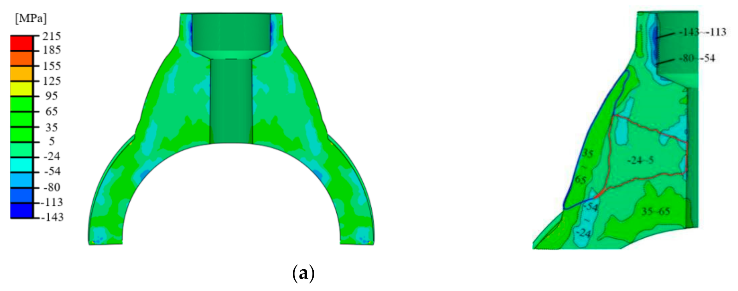
  • The compressive residual stress is formed in the original 316L weld, and a higher compressive stress (−50 MPa) and a lager compressive area can be observed in the longitudinal section.
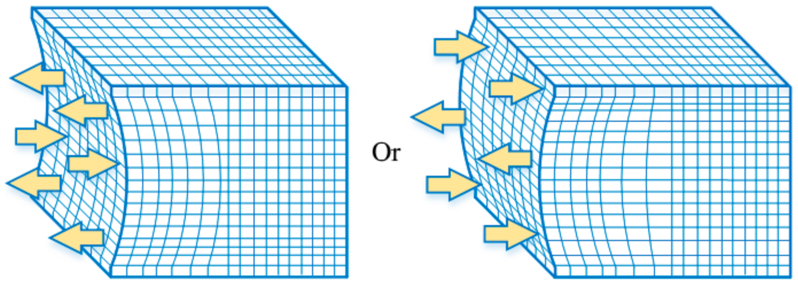
  • The 10-mm-thick overlay repair process can introduce compressive stress into the crack located in the original weld, which is beneficial for crack closure and provides both time saving and economic benefits for repair welding.

Author Contributions

Writing—original draft preparation, Q.C.; Writing—review and editing, X.K.; Investigation, W.T. All authors have read and agreed to the published version of the manuscript.

Funding

This research received no external funding.

Data Availability Statement

Data sharing is not applicable to this article.

Acknowledgments

The authors thank the referees of this study for their valuable and very helpful comments.

Conflicts of Interest

The authors declare no conflict of interest.

References

  1. Liooold, J.C. Welding Metallurgy and Weldability; Wiley: Hoboken, NJ, USA, 2015; pp. 130–139. [Google Scholar]
  2. Fink, C. An investigation on ductility-dip cracking in the base metal heat-affected zone of wrought nickel base alloys—part I: Metallurgical effects and cracking mechanism. Weld. World 2016, 60, 939–950. [Google Scholar] [CrossRef]
  3. Hua, C.; Lu, H.; Yu, C. Reduction of ductility-dip cracking susceptibility by ultrasonic-assisted GTAW. J. Mater. Process. Technol. 2017, 239, 240–250. [Google Scholar] [CrossRef]
  4. Dong, P.; Hong, J.K.; Bouchard, P.J. Analysis of residual stresses at weld repairs. Int. J. Press. Vessel. Pip. 2005, 82, 258–269. [Google Scholar] [CrossRef]
  5. Bouchard, P.J.; George, D.; Santisteban, J.R. Measurement of the residual stresses in a stainless steel pipe girth weld containing long and short repairs. Int. J. Press. Vessel. Pip. 2005, 82, 299–310. [Google Scholar] [CrossRef]
  6. Lant, T.; Robinson, D.; Spafford, B.; Storesund, J. Review of Weld Repair Procedures for Low Alloy Steels Designed to Minimise the Risk of Future Cracking. Int. J. Press. Vessel. Pip. 2001, 78, 813–818. [Google Scholar] [CrossRef]
  7. Branza, T.; Deschaux-Beaume, F.; Sierra, G.; Lours, P. Study and Prevention of Cracking during Weld-Repair of Heat-Resistant Cast Steels. J. Mater. Process. Technol. 2009, 209, 536–547. [Google Scholar] [CrossRef] [Green Version]
  8. Aloraier, A.; Al-Mazrouee, A.; Price, J.; Shehata, T. Weld Repair Practices without Post Weld Heat Treatment for Ferritic Alloys and Their Consequences on Residual Stresses: A Review. Int. J. Press. Vessel. Pip. 2010, 87, 127–133. [Google Scholar] [CrossRef]
  9. Guo, Q.; Du, B.; Xu, G. Influence of filler metal on residual stress in multi-pass repair welding of thick P91 steel pipe. Int. J. Adv. Manuf. Technol. 2020, 110, 2977–2989. [Google Scholar] [CrossRef]
  10. Charkhi, M.; Akbari, D. Experimental and Numerical Investigation of the Effects of the Pre-Heating in the Modification of Residual Stresses in the Repair Welding Process. Int. J. Press. Vessel. Pip. 2019, 171, 79–91. [Google Scholar] [CrossRef]
  11. Perić, M.; Nižetić, S.; Tonković, Z. Numerical Simulation and Experimental Investigation of Temperature and Residual Stress Distributions in a Circular Patch Welded Structure. Energies 2020, 13, 54. [Google Scholar] [CrossRef]
  12. Xiao, X.; Liu, Q.; Hu, M.; Li, K.; Cai, Z. Effect of Welding Sequence and the Transverse Geometry of the Weld Overlay on the Distribution of Residual Stress in the Weld Overlay Repair of T23 Tubes. Metals 2021, 11, 568. [Google Scholar] [CrossRef]
  13. Moattari, M.; Shokrieh, M.; Moshayedi, H. Effects of Residual Stresses Induced by Repair Welding on the Fracture Toughness of Ni-Based IN939 Alloy. Theor. Appl. Fract. Mech. 2020, 108, 102614. [Google Scholar] [CrossRef]
  14. Shankar, K.; Wu, W. Effect of Welding and Weld Repair on Crack Propagation Behaviour in Aluminium Alloy 5083 Plates. Mater. Des. 2002, 23, 201–208. [Google Scholar] [CrossRef]
  15. Prime, M.B.; Gonzales, A.R. The contour method: Simple 2-D mapping of residual stresses. In Proceedings of the Sixth International Conference on Residual Stress, Oxford, UK, 10–12 July 2000; pp. 617–624. [Google Scholar]
  16. Schajer, G.S. Practical Residual Stress Measurement Methods; John Wiley & Sons: Hoboken, NJ, USA, 2013. [Google Scholar]
  17. Hosseinzadeh, F.; Bouchard, J.; Kowal, J. Towards good practice guidelines for the contour method of residual stress measurement. J. Eng. 2014, 51, 685–693. [Google Scholar] [CrossRef]
  18. Olson, M.D.; Dewald, A.T.; Prime, M.B.; Hill, M.R. Estimation of Uncertainty for Contour Method Residual Stress Measurements. Exp. Mech. 2014, 55, 577–585. [Google Scholar] [CrossRef]
  19. Shin, S.H. FEM Analysis of Plasticity-Induced Error on Measurement of Welding Residual Stress by the Contour Method. J. Mech. Sci. Technol. 2005, 19, 1885–1890. [Google Scholar] [CrossRef]
  20. Behrens, B.-A.; Gibmeier, J.; Brunotte, K.; Wester, H.; Simon, N.; Kock, C. Investigations on Residual Stresses Within Hot-Bulk-Formed Components Using Process Simulation and the Contour Method. Metals 2021, 11, 566. [Google Scholar] [CrossRef]
  21. Sun, Y.L.; Roy, M.J.; Vasileiou, A.N. Evaluation of Errors Associated with Cutting-Induced Plasticity in Residual Stress Measurements Using the Contour Method. Exp. Mech. 2017, 57, 1–16. [Google Scholar] [CrossRef] [Green Version]
  22. Achouri, A.; Hosseinzadeh, F.; Bouchard, P.J. The incremental contour method using asymmetric stiffness cuts. Mater. Des. 2020, 197, 109268. [Google Scholar] [CrossRef]
  23. Saukkonen, T.; Aalto, M.; Virkkunen, I.; Ehrnstén, U.; Hänninen, H. Plastic Strain and Residual Stress Distributions in an AISI 304 Stainless Steel BWR Pipe Weld; John Wiley & Sons, Inc.: Hoboken, NJ, USA, 2011. [Google Scholar]
  24. Hicks, T.G.; Mabe, W.R.; Miller, J.R.; Mullen, J.V. Evaluation of Residual Stresses Induced by Repairs to Small Diameter Stainless Steel Pipe Welds. In Proceedings of the ASME 2015 Pressure Vessels and Piping Conference, Boston, MA, USA, 19–23 July 2015. [Google Scholar]
  25. Rogalski, G.; Świerczyńska, A.; Landowski, M.; Fydrych, D. Mechanical and Microstructural Characterization of TIG Welded Dissimilar Joints between 304L Austenitic Stainless Steel and Incoloy 800HT Nickel Alloy. Metals 2020, 10, 559. [Google Scholar] [CrossRef]
  26. Dokme, F.; Kulekci, M.; Esme, U. Microstructural and Mechanical Characterization of Dissimilar Metal Welding of Inconel 625 and AISI 316L. Metals 2018, 8, 797. [Google Scholar] [CrossRef] [Green Version]
  27. Smith, M.; Levesque, J.B.; Bichler, L. Residual stress analysis in linear friction welded in-service Inconel 718 superalloy via neutron diffraction and contour method approaches. Mater. Sci. Eng. 2017, 691, 168–179. [Google Scholar] [CrossRef]
  28. Prakash, C.; Krolczyk, G.; Singh, S.; Pramanik, A. (Eds.) Advances in Metrology and Measurement of Engineering Surfaces; Select Proceedings of ICFMMP; Springer: Singapore, 2021. [Google Scholar]
  29. Lei, Z.; Zou, J.; Wang, D. Finite-element inverse analysis of residual stress for laser welding based on a contour method. Opt. Laser Technol. 2020, 129, 106289. [Google Scholar] [CrossRef]
Figure 1. The principle of the contour method.
Metals 11 01109 g001
Figure 2. Dimensions of the T-pipe joint.
Metals 11 01109 g002
Figure 3. Dimension of overlay weld.
Metals 11 01109 g003
Figure 4. Section cutting directions.
Metals 11 01109 g004
Figure 5. Models of stress calculation.
Metals 11 01109 g005
Figure 6. Displacement distribution on the two cut surfaces: (a) displacement distribution for the section cut along the circumferential direction; (b) displacement distribution for the section cut along the longitudinal direction.
Metals 11 01109 g006
Figure 7. Residual stress distribution: (a) stress distribution in the circumferential cut surface; (b) stress distribution in the longitudinal cut surface.
Metals 11 01109 g007aMetals 11 01109 g007b
Figure 8. Residual stress along different paths: (a) stress distribution along Path1 and Path5; (b) stress distribution along Path2 to Path4 and Path6 to Path8.
Metals 11 01109 g008aMetals 11 01109 g008b
Table 1. Summary of the test component dimensions.
ComponentBase MaterialOuter Radius, R0 (mm)Wall Thickness, t (mm)Length, L (mm)
Main pipeZ2CND18.12N168.318.26335
Branch pipeZ2CND18.12N6021.560
Table 2. Summary of the welding parameters.
Weld TypePeak Current (A)Base Current (A)Voltage (V)Duration (ms)Pulse Width (s)Diameter of the Wire (mm)Welding Speed (mm·min−1)
MMA90203.2150
TIG22015490.20.20.9110
Table 3. Chemical compositions.
Z2CND18.12NelementCSiMnPSCrNiMo
content/%0.0270.421.220.0050.00218.489.980.193
ER316LelementCSiMnPSCrNiMo
content/%0.0160.501.860.0300.00618.9210.691.25
ERNiCRFe-7AelementCSiMnPSCrNiMo
content/%0.0380.400.50.0130.00929.64balance0.017
elementCuFeTiAlNbBZrCo
content/%0.01310.140.0670.0721.690.00160.00060.016
Table 4. Mechanical properties.
MaterialElastic Modulus (GPa)Poisson’s Ratio
Z2CND18.12N2000.3
ER316L2000.3
ERNiCrFe-7A2030.3
Publisher’s Note: MDPI stays neutral with regard to jurisdictional claims in published maps and institutional affiliations.

