Extension of Gap Bridgeability and Prevention of Oxide Lines in the Welding Seam through Application of Tools with Multi-Welding Pins

Abstract
:1. Introduction
2. Experimental Procedure
Further Information on the Methods
3. Results
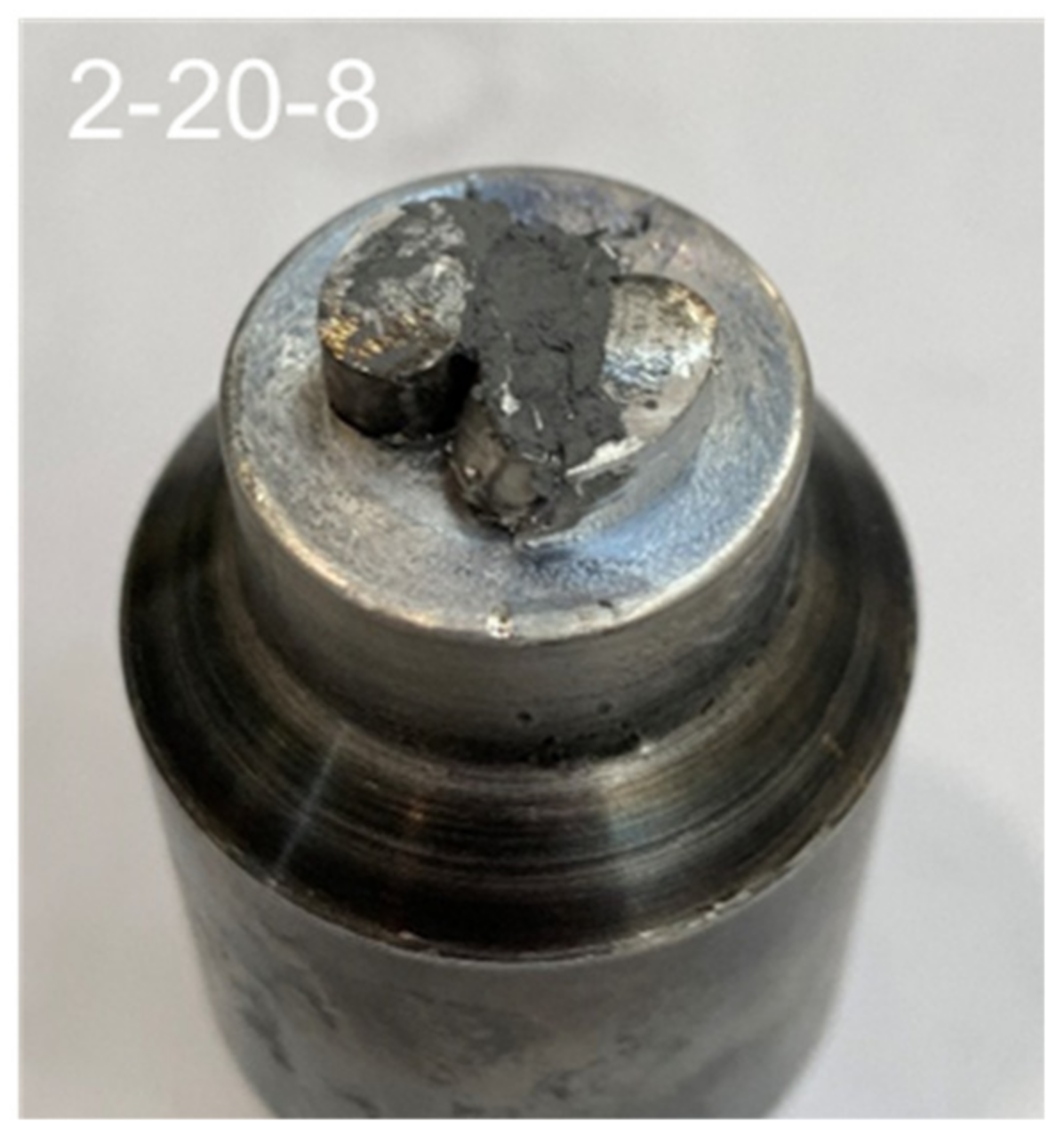
3.1. Concept of a Multi-Pin Tool
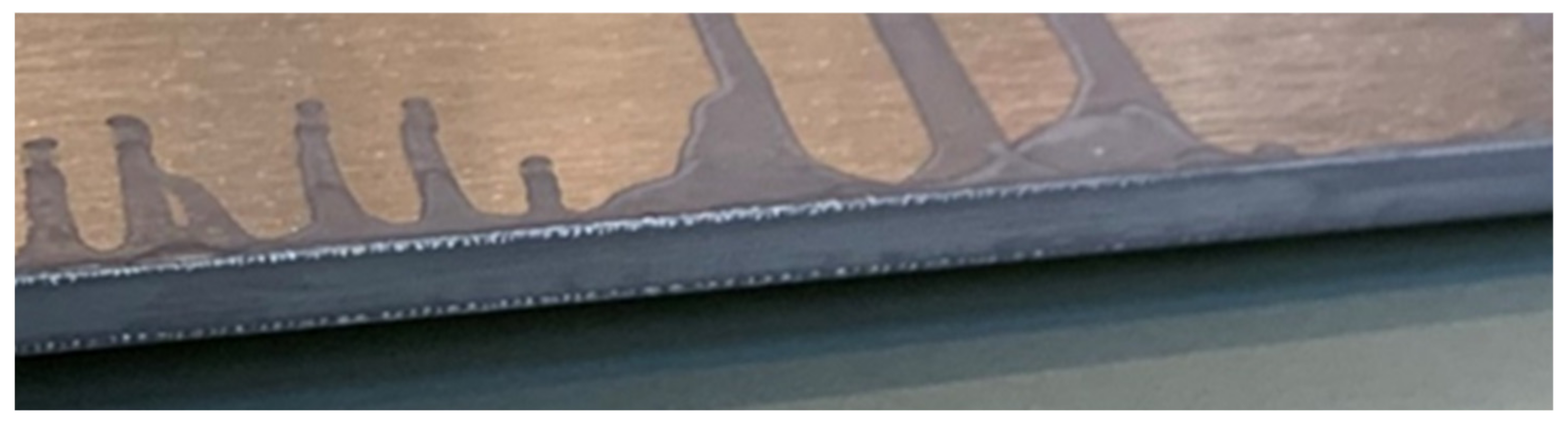
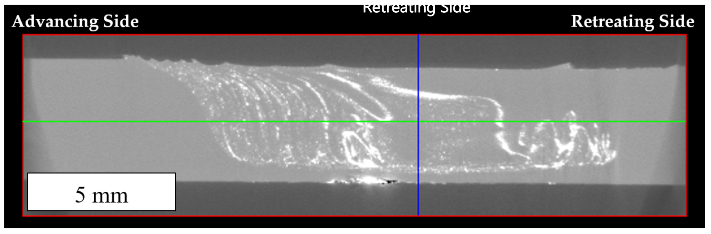
3.2. Influence of a Multi-Pin Tool on the Oxide Line Distribution
Exchange of Material between the Welding Pins
3.3. Parameter Study for the Use of Multi-Pin Tools
3.4. Increased Gap Bridgeability through the Use of Multi-Pin Tools
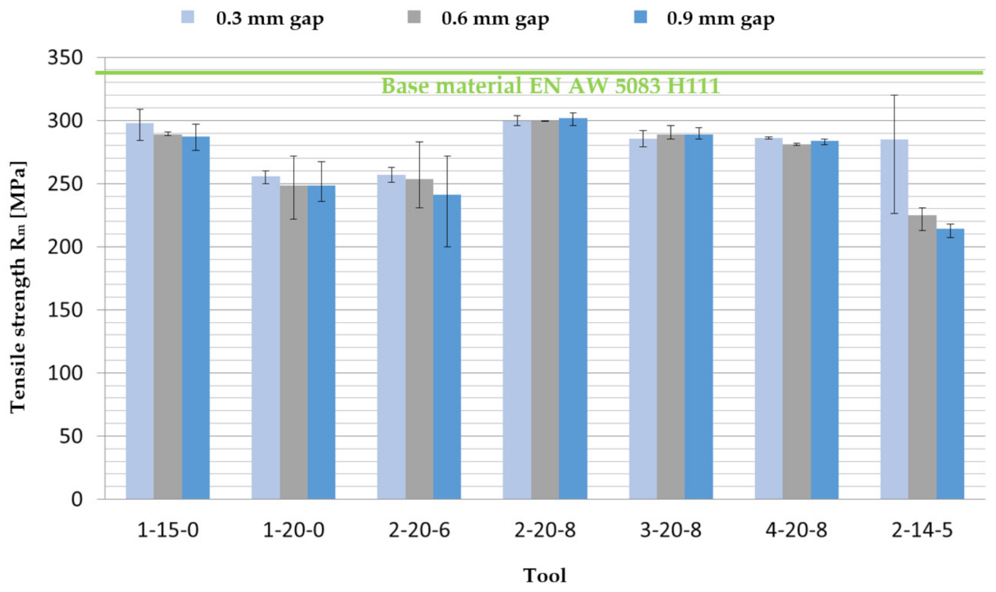
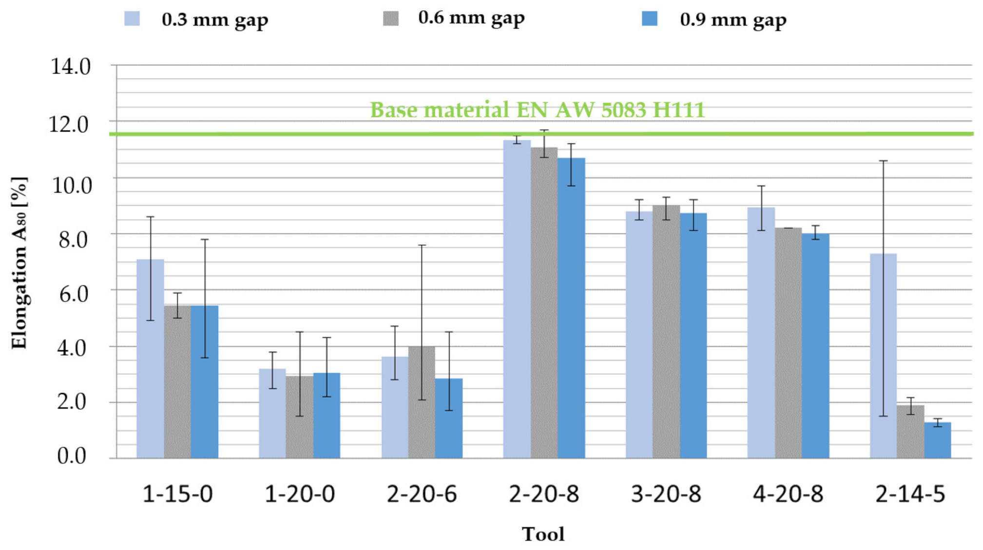
3.4.1. Evaluation of the Tests with the Material EN AW 5083 H111
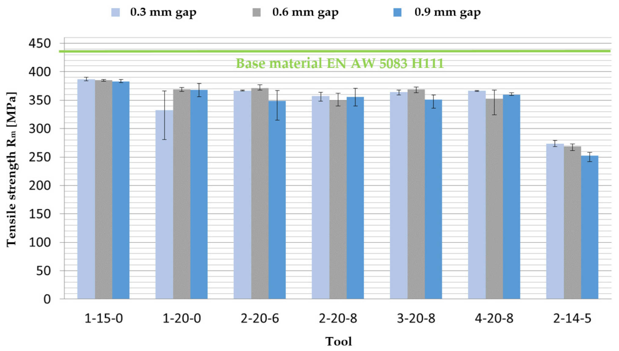
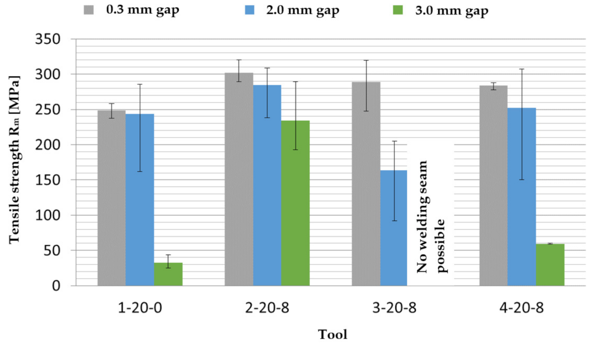
Tensile Tests
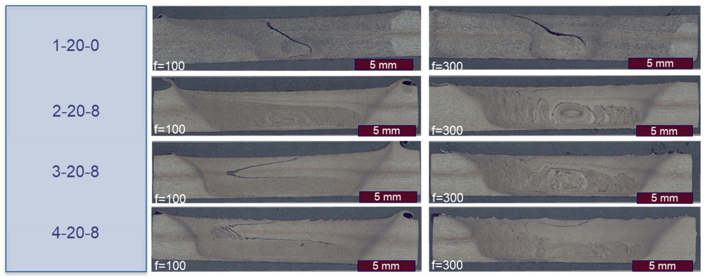
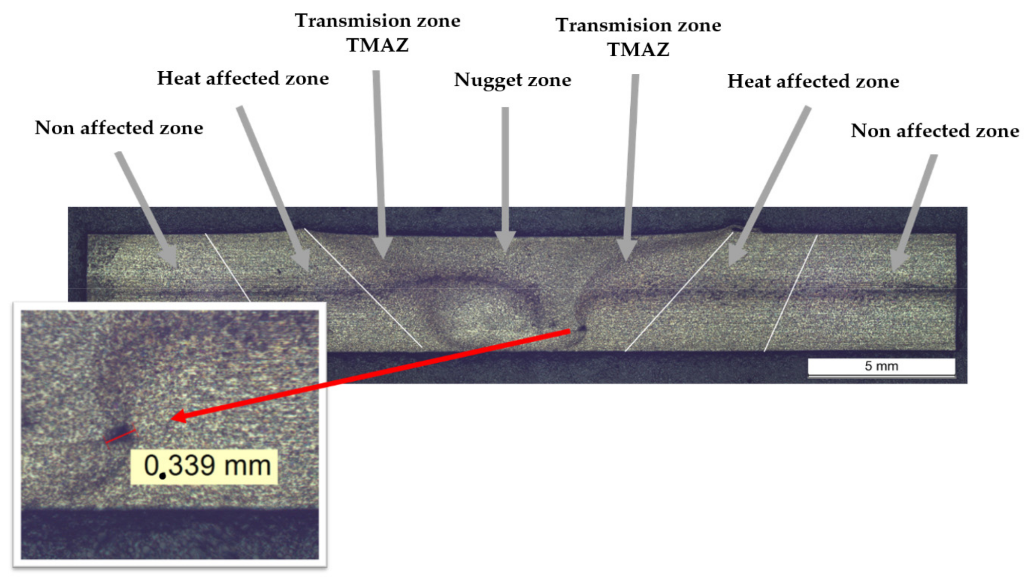
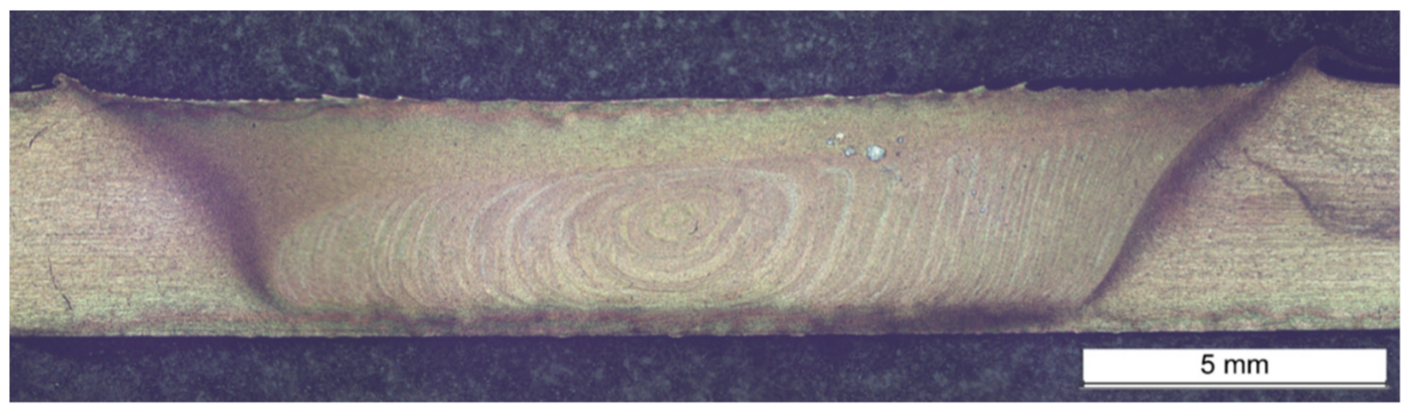
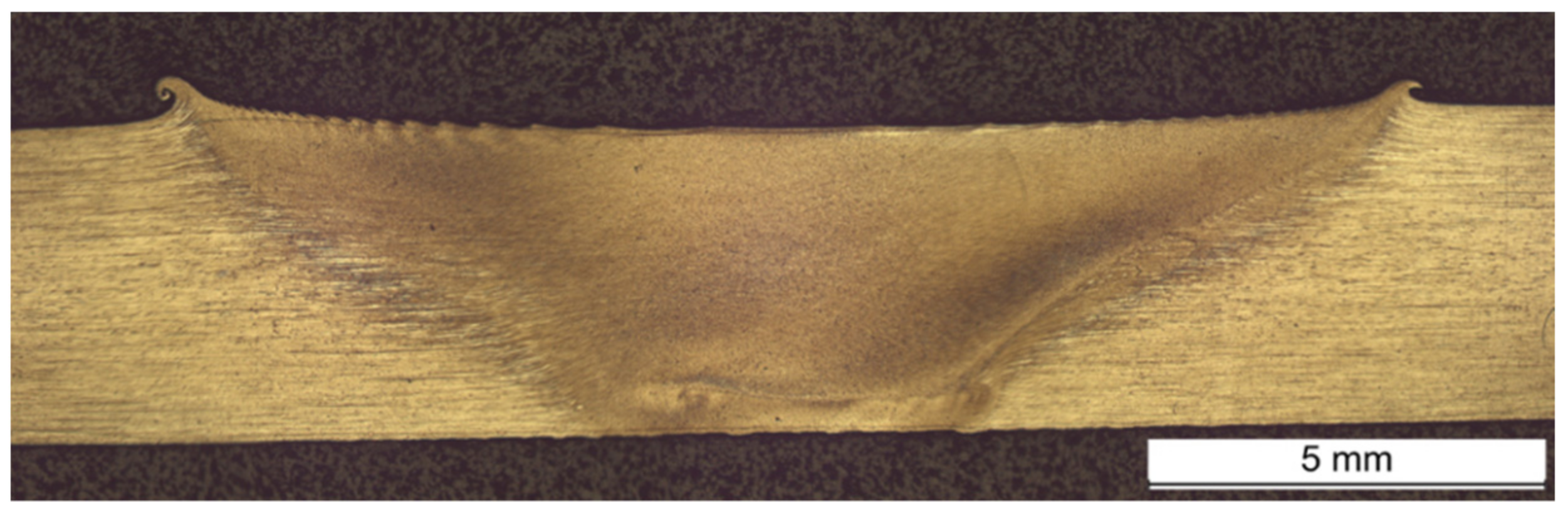
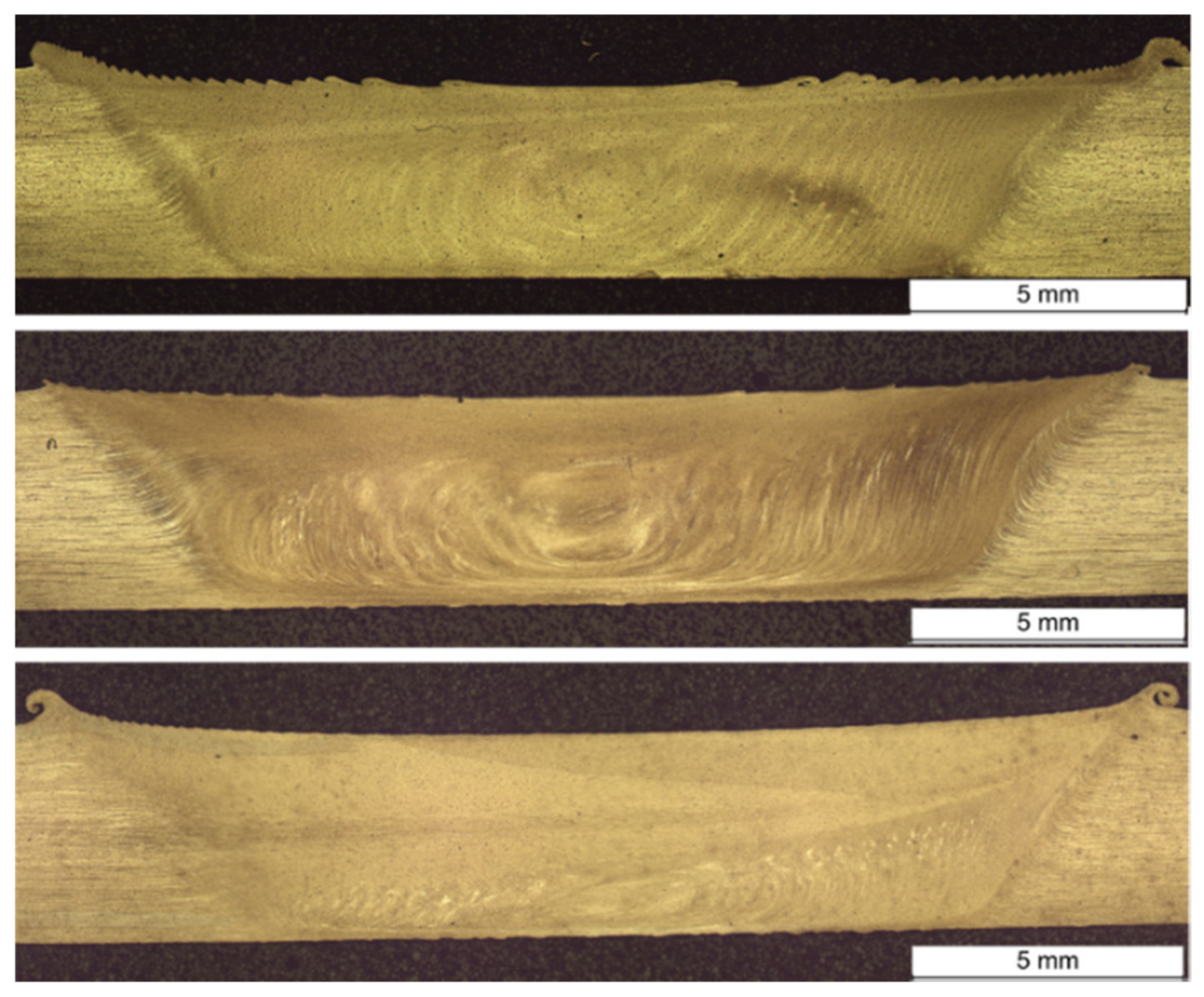
Cross Sections
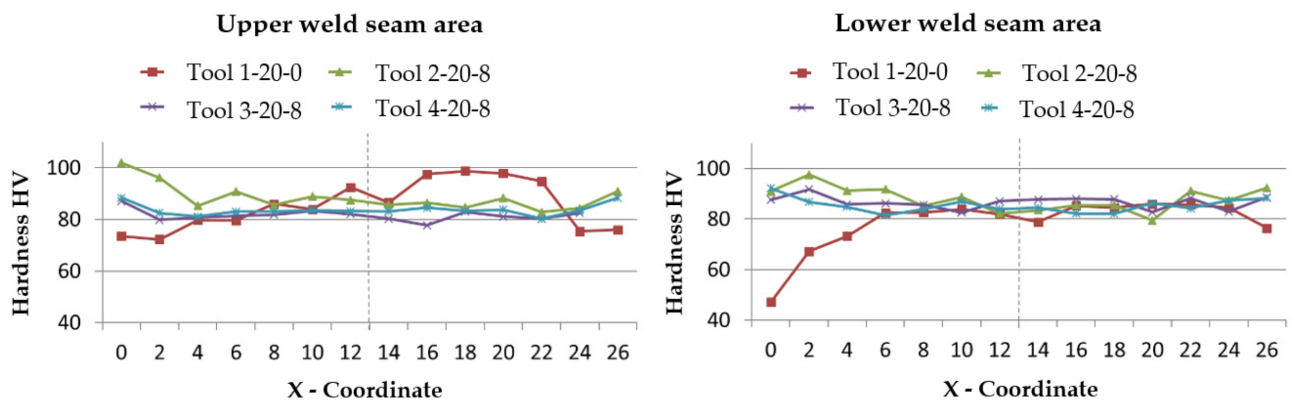
Hardness Measurement
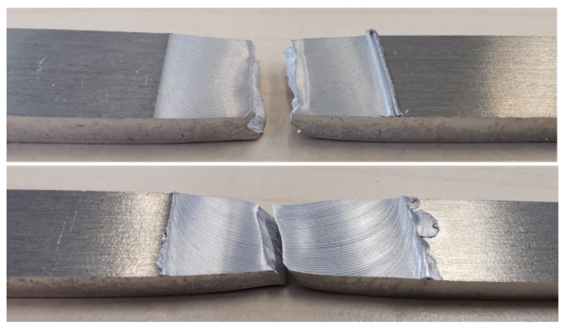
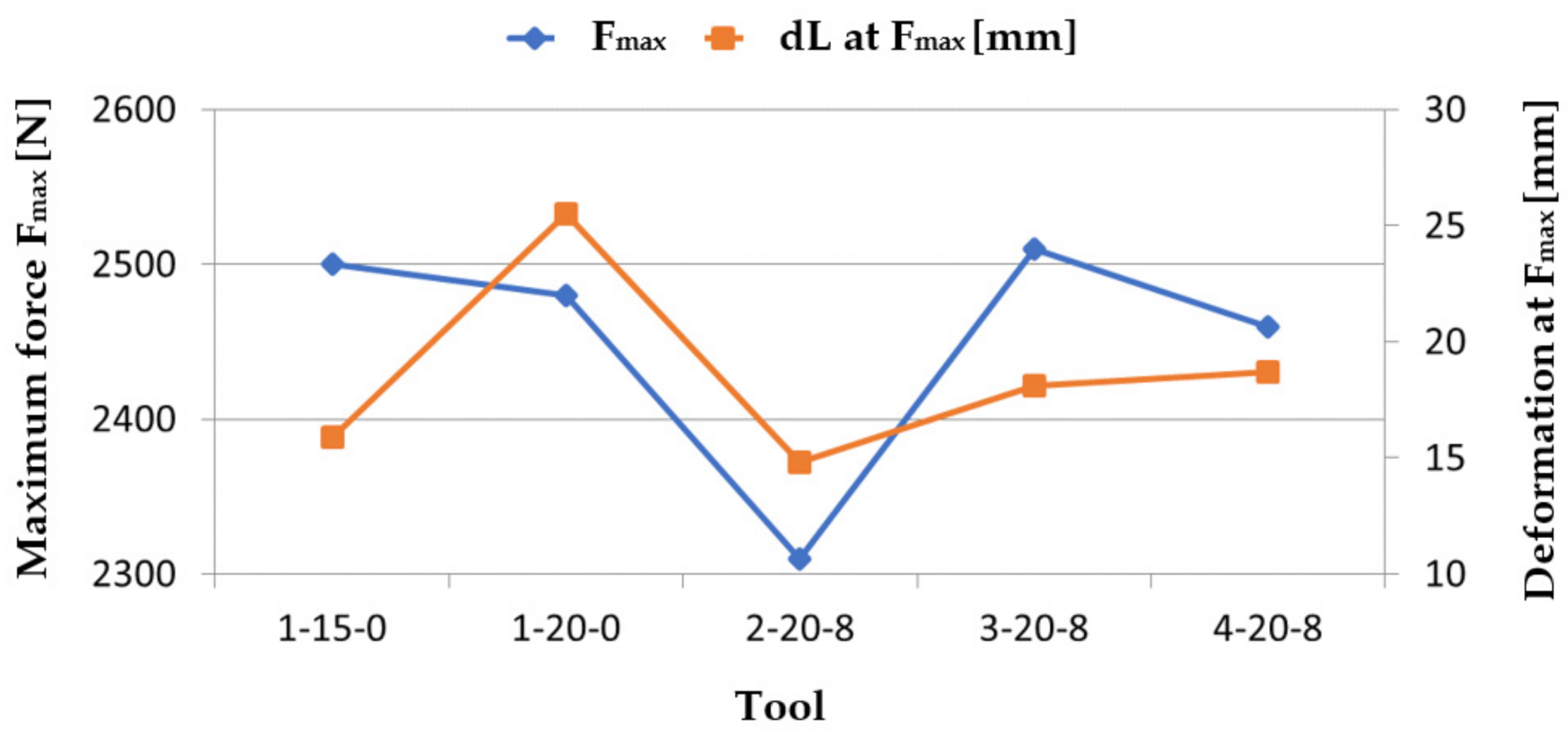
Bending Test
3.4.2. Evaluation of the Tests with the Material EN AW 7020 T651
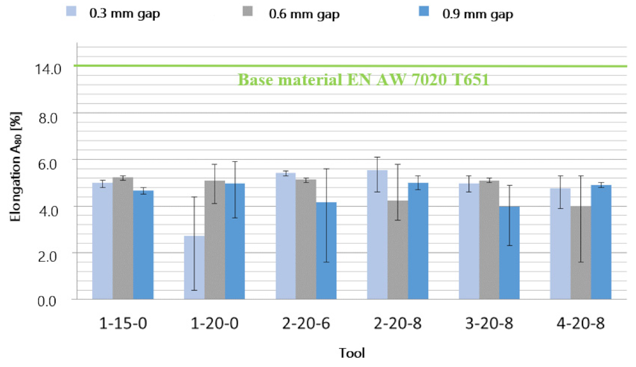
Tensile Test
Cross Sections
Hardness Measurement
Bending Test
3.5. Increase of the Joint Gap
4. Discussion
4.1. Microstructure
4.2. Welding Seam Properties
5. Conclusions
Author Contributions
Funding
Institutional Review Board Statement
Informed Consent Statement
Data Availability Statement
Acknowledgments
Conflicts of Interest
References
- Sedmak, A.S.; Ratnesh, K.; Somnath, C.; Sergej, H.; Srdjan, S.T.; Andrijana, A.D.; Ivana, R.Č.; Elisaveta, D. Heat Input Effect of Friction Stir Welding on Aluminum Alloy AA 6061-T6 Welded Joint. Therm. Sci. 2016, 20, 637–641. [Google Scholar] [CrossRef]
- Veljic, D.; Perović, M.; Sedmak, A.; Marko, R.; Nikola, B.; Medjo, B.; Dascau, H. Numerical simulation of the plunge stage in friction stir welding. Struct. Integr. Life 2011, 11, 131–134. [Google Scholar]
- Veljic, D.; Perovic, M.; Sedmak, A.; Rakin, M.; Trifunovic, M.; Bajic, N.; Bajic, D. A coupled thermo-mechanical model of friction stir welding. Therm. Sci. 2012, 16, 527–534. [Google Scholar] [CrossRef]
- Mishra, R.S.; Ma, Z. Friction stir welding and processing. Mater. Sci. Eng. Rep. 2005, 50, 1–78. [Google Scholar] [CrossRef]
- DIN EN ISO 25239-1: 2012-03. Rührreibschweißen_-Aluminium_-Teil_1: Begriffe (ISO_25239-1: 2011); Dreisprachige Fassung EN_ISO_25239-1: 2011; DIN: Berlin, Germany, 2012. [Google Scholar]
- Völlner, G. Rührreibschweißen mit Schwerlast-Industrierobotern; 1. Auflage, s.l.; Herbert Utz Verlag: Munich, Germany, 2010. [Google Scholar]
- Schüddekopf, S.; Pukies, C.; Rebensdorf, A.; Böhm, S.; Schüddekopf, S. Einsatz von Rührreibschweißwerkzeugen mit Mehreren Stiften zur Vermeidung von Oxidansammlungen bei Gleichzeitiger Erweiterung der Spaltüberbrückbarkeit; Rührreibschweißen und Verwandte Verfahren: Geesthacht, Germany, 2016. [Google Scholar]
- Fachgebiet Trennende und Fügende Fertigungsverfahren (tff): Ausstattung Portalrührreibschweiß-Maschine. Available online: https://www.tff-kassel.de/ausstattung/ (accessed on 8 April 2019).
- DIN EN 573-3: 2013-12. Aluminium und Aluminiumlegierungen_-Chemische Zusammensetzung und Form von Halbzeug_-Teil_3: Chemische Zusammensetzung und Erzeugnisformen; Deutsche Fassung EN_573-3: 2013; DIN: Berlin, Germany, 2013. [Google Scholar]
- Ostermann, F. Anwendungstechnologie Aluminium; Springer: Berlin/Heidelberg, Germany, 2014. [Google Scholar]
- DIN EN 485-2: 2018-12. Aluminium und Aluminiumlegierungen_-Bänder, Bleche und Platten_-Teil_2: Mechanische Eigenschaften; Deutsche Fassung EN_485-2:2016+A1: 2018; DIN: Berlin, Germany, 2018. [Google Scholar]
- DIN EN 515: 2017-05. Aluminium und Aluminiumlegierungen_-Halbzeug_-Bezeichnungen der Werkstoff-Zustände; Deutsche Fassung EN_515: 2017; Beuth Verlag GmbH: Berlin, Germany, 2017. [Google Scholar]
- Mishra, R.S.; De, P.S.; Kumar, N. Friction Stir Welding and Processing; Springer International Publishing: Cham, Switzerland, 2014. [Google Scholar]
- Mahoney, M.W.; Mishra, R.S. Friction Stir Welding and Processing; ASM International: Materials Park, OH, USA, 2007. [Google Scholar]
- DIN EN ISO 6892-1: 2017-02. Metallische Werkstoffe_-Zugversuch_-Teil_1: Prüfverfahren bei Raumtemperatur (ISO_6892-1: 2016); Deutsche Fassung EN_ISO_6892-1: 2016; Beuth Verlag GmbH: Berlin, Germany, 2016. [Google Scholar]
- Rhodes, C.; Mahoney, M.; Bingel, W.; Spurling, R.; Bampton, C. Effects of friction stir welding on microstructure of 7075 aluminum. Scr. Mater. 1997, 36, 69–75. [Google Scholar] [CrossRef]


| Element | Si | Fe | Cu | Mn | Mg | Cr | Zn | Ti | Al |
|---|---|---|---|---|---|---|---|---|---|
| Percentage [%] | 0.40 | 0.40 | 0.10 | 0.40–1.0 | 4.00–4.90 | 0.05–0.25 | 0.25 | 0.15 | Remaining |
| Properties | EN AW 5083 H111 |
|---|---|
| [MPa] | 275 |
| [MPa] | 125 |
| [%] | 15 |
| Hardness [HBW] | 75 |
| Element | Si | Fe | Cu | Mn | Mg | Cr | Zn | Ti | Al |
|---|---|---|---|---|---|---|---|---|---|
| Percentage [%] | 0.35 | 0.40 | 0.20 | 0.05–0.50 | 1.00–1.40 | 0.10–0.35 | 4.00–5.00 | - | Remaining |
| Properties | EN AW 7020 T651 |
|---|---|
| [MPa] | 350 |
| [MPa] | 280 |
| [%] | 10 |
| Hardness [HBW] | 104 |
| Number of Pins | |||||
|---|---|---|---|---|---|
| 1 | 15 | - | 5 | 5 | 0.33 |
| 1 | 20 | - | 5 | 5 | 0.25 |
| 2 | 14 | 5 | 4 | 9 | 0.64 |
| 2 | 14 | 6 | 4 | 10 | 0.71 |
| 2 | 20 | 6 | 5 | 11 | 0.55 |
| 2 | 20 | 8 | 5 | 13 | 0.65 |
| 3 | 20 | 8 | 5 | 13 | 0.65 |
| 4 | 20 | 8 | 5 | 13 | 0.65 |
| Tool Name | EN AW 5083 H111 | EN AW 7020 T651 | ||
|---|---|---|---|---|
| Tool | Rotation Speed [rpm] | [mm/min] | Rotation Speed [rpm] | [mm/min] |
| 1-15-0 | 600 | 200 | 600 | 200 |
| 1-20-0 | 600 | 200 | 600 | 200 |
| 2-14-5 | 300 | 100 | 900 | 300 |
| 2-15-6 | 300 | 100 | 600 | 200 |
| 2-20-6 | 750 | 250 | 600 | 200 |
| 2-20-8 | 450 | 150 | 300 | 100 |
| 3-20-8 | 300 | 100 | 300 | 100 |
| 4-20-8 | 300 | 100 | 300 | 100 |
Publisher’s Note: MDPI stays neutral with regard to jurisdictional claims in published maps and institutional affiliations. |
© 2021 by the authors. Licensee MDPI, Basel, Switzerland. This article is an open access article distributed under the terms and conditions of the Creative Commons Attribution (CC BY) license (https://creativecommons.org/licenses/by/4.0/).
Share and Cite
Hatzky, M.; Böhm, S. Extension of Gap Bridgeability and Prevention of Oxide Lines in the Welding Seam through Application of Tools with Multi-Welding Pins. Metals 2021, 11, 1219. https://doi.org/10.3390/met11081219
Hatzky M, Böhm S. Extension of Gap Bridgeability and Prevention of Oxide Lines in the Welding Seam through Application of Tools with Multi-Welding Pins. Metals. 2021; 11(8):1219. https://doi.org/10.3390/met11081219
Chicago/Turabian StyleHatzky, Marcel, and Stefan Böhm. 2021. "Extension of Gap Bridgeability and Prevention of Oxide Lines in the Welding Seam through Application of Tools with Multi-Welding Pins" Metals 11, no. 8: 1219. https://doi.org/10.3390/met11081219
APA StyleHatzky, M., & Böhm, S. (2021). Extension of Gap Bridgeability and Prevention of Oxide Lines in the Welding Seam through Application of Tools with Multi-Welding Pins. Metals, 11(8), 1219. https://doi.org/10.3390/met11081219