Tensile Tests
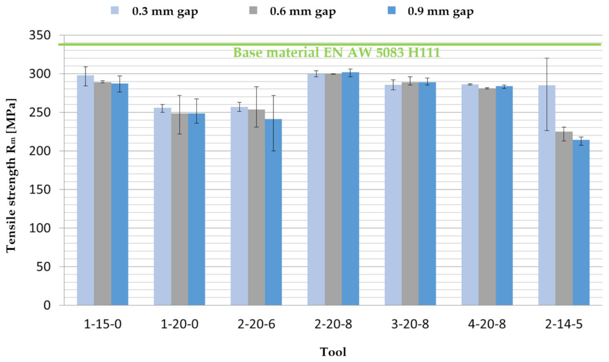
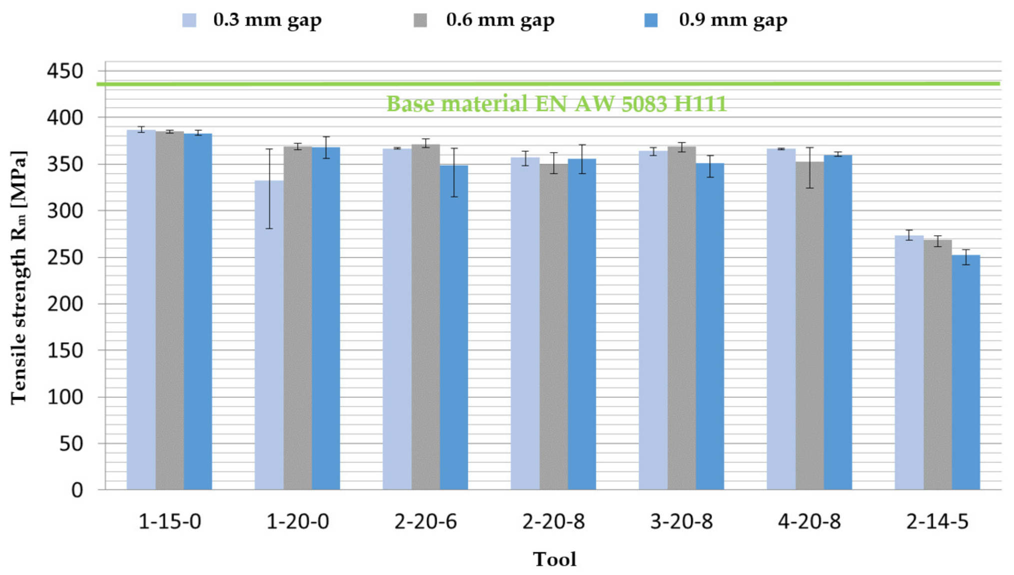
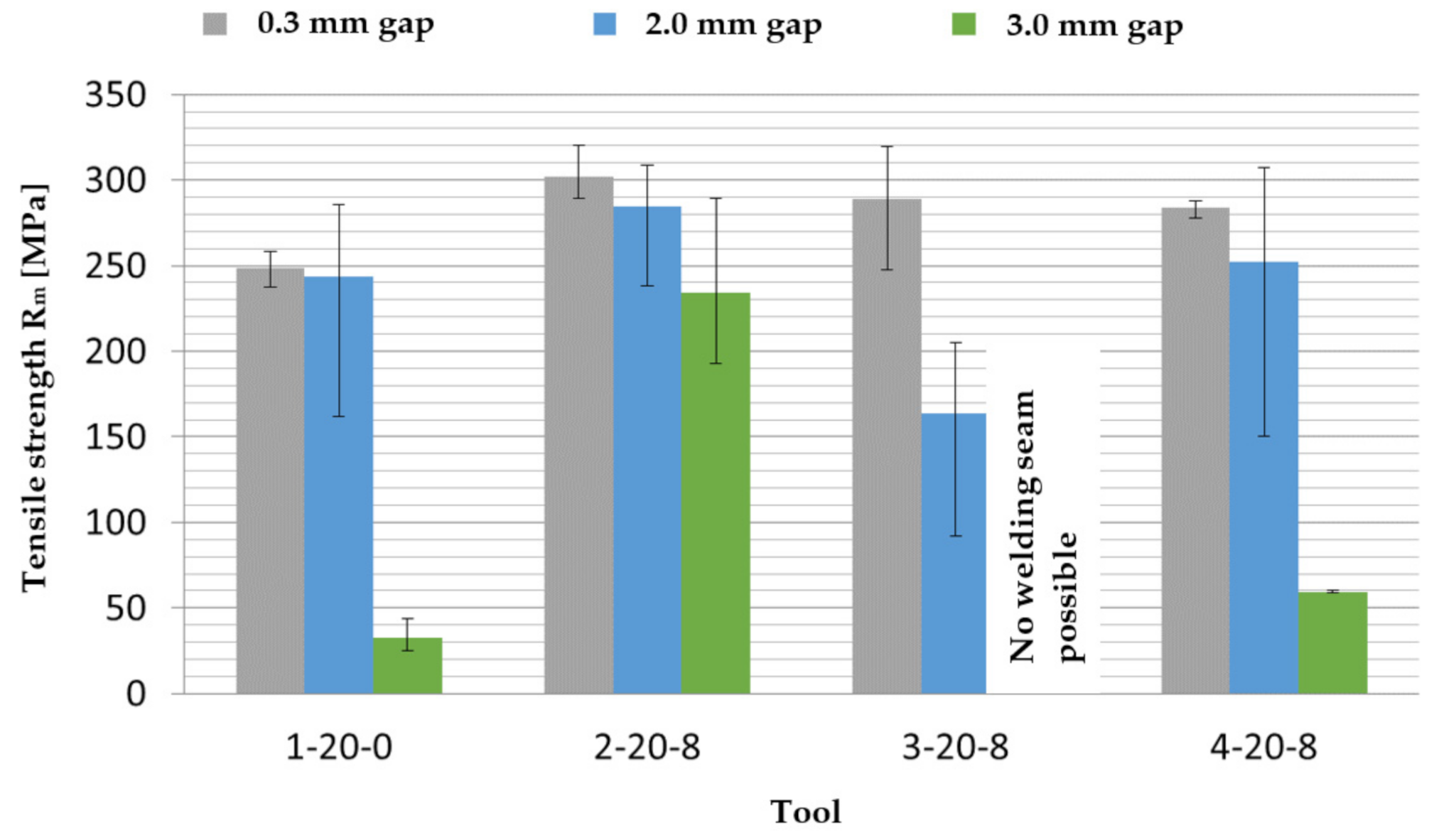
Primarily, the tensile strengths of the tests welded with different joint gap widths should give an overview of the welding seam qualities. For this purpose, the mean values of the tensile strengths of the three tensile test specimens are to be taken from a weld of
Figure 12. The evaluation focuses on the results of the multi-pin tools. The results of the tensile strength
of the base material, which is represented by the green line in the diagram, serve as reference values.
When looking at the tensile strength, a tendency can be seen that the tensile strength decreases with increasing joint gap. However, the multi-pin tools 2-20-8, 3-20-8 and 4-20-8, whose welds each have almost constant tensile strengths, are an exception. For welds with these tools, despite increasing joint gap widths up to 0.9 mm or 22.5% of the sheet thickness, no influence of the joint gap width on the tensile strength was observed. The tool 2-20-8, whose welds show a high and constant level of tensile strength of about 300 MPa, is particularly noteworthy. This value corresponds to a welding seam strength of about 92% of the base material evaluated as reference value and is not reached by any of the other tools. However, tools 3-20-8 and 4-20-8 with a tensile strength of approximately 280–290 MPa and about 86–89% of the base material strength also show good welding seam strengths at the set joint gap widths of up to 0.9 mm. The minimum values for the tensile strength of 275 MPa required by DIN EN 485-2 are achieved for all welded joints welded with tools 2-20-8, 3-20-8 and 4-20-8. This indicates a high-quality welding seam. The lowest tensile strength level, which is strongly dependent on the joint gap width, is shown by the two-pin tool 2-14-5.
By means of the error indicators shown in
Figure 12, the minimum and maximum values of the achieved tensile strength
of the tensile specimens 1–3 of a single welding seam with a certain underlying joint gap width in each case can be identified. The difference between the respective minimum and maximum tensile strength values indicates the consistency of the strength in the course of a welding seam. The fluctuation within a welding seam is relatively high, e.g., in the case of tool 2-20-6, especially for the joint gap widths of 0.6 mm and 0.9 mm. The maximum stresses of the tensile specimens 1–3 within the welding seam, which was welded with a joint gap of 0.9 mm, vary from 200 MPa up to 272 MPa. The fluctuating tensile strengths indicate that stable and constant welding seam properties over the entire length of the welding seam cannot be achieved with the tool. The multi-pin tools 2-20-8, 3-20-8, and 4-20-8, on the other hand, show relatively constant mean values of the tensile strengths over the different gap widths up to 0.9 mm. Furthermore, the fluctuations within the individual welding seams are also very small. This indicates that the weld has stable and uniform properties over the entire length of the seam and that solid welded joints can be produced.
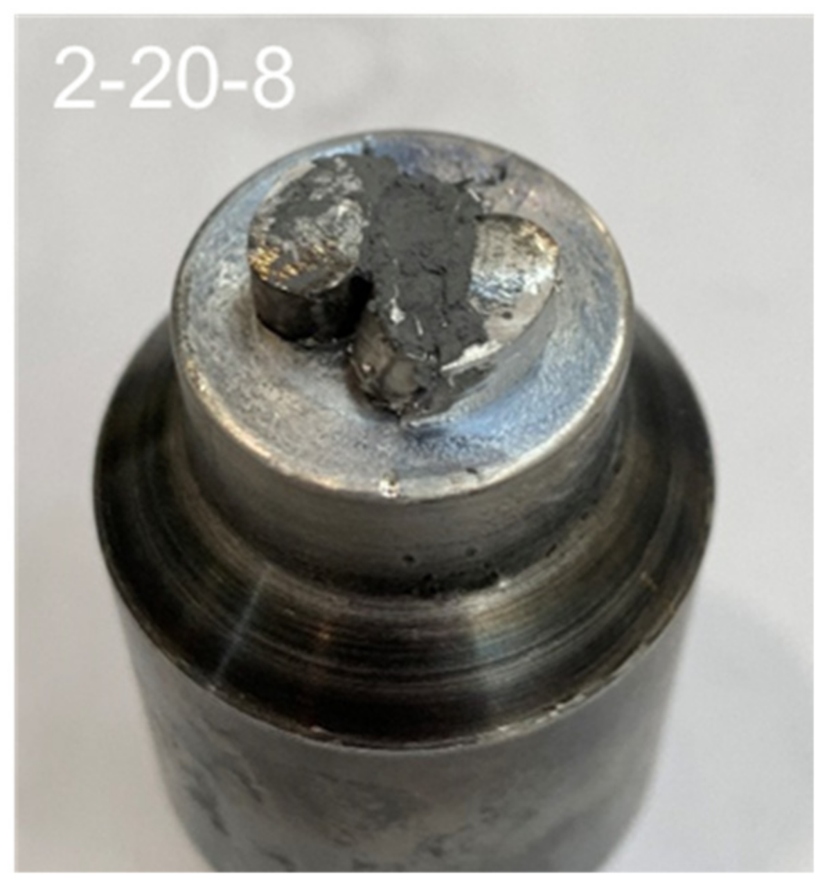
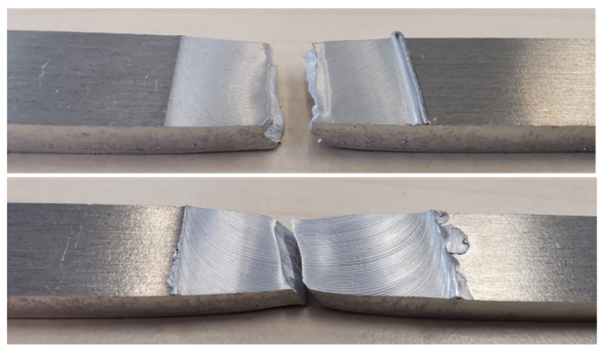
When looking at the fractured surfaces, it can be seen that the tensile specimens break exclusively in the area of the welding seam and mostly in the area of the stirring zone in the middle of the seam. On closer inspection, it is noticeable that the tensile specimens from the welding tests carried out with tool 2-20-8, as shown in
Figure 13, are more constricted than the other tensile specimens.
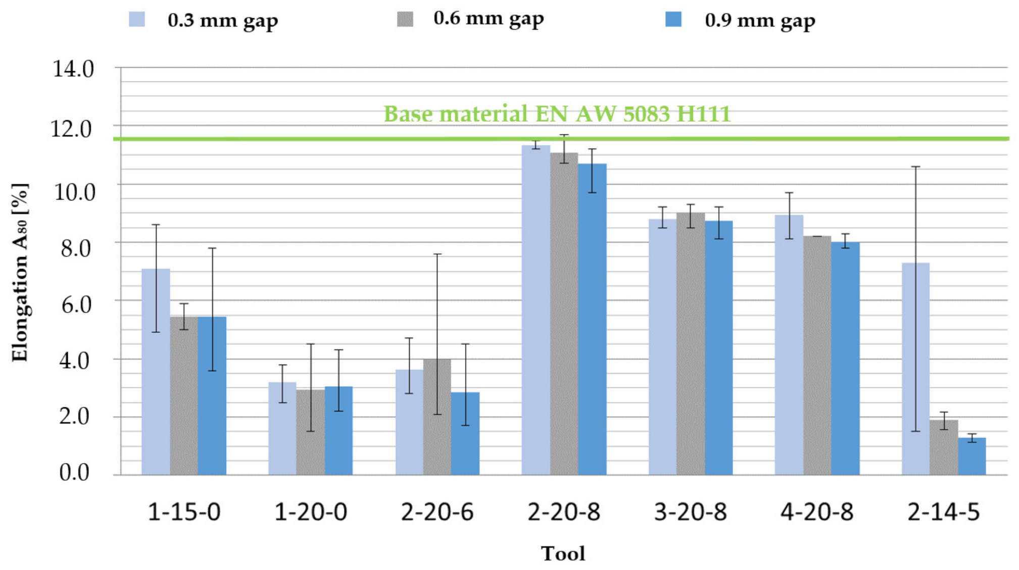
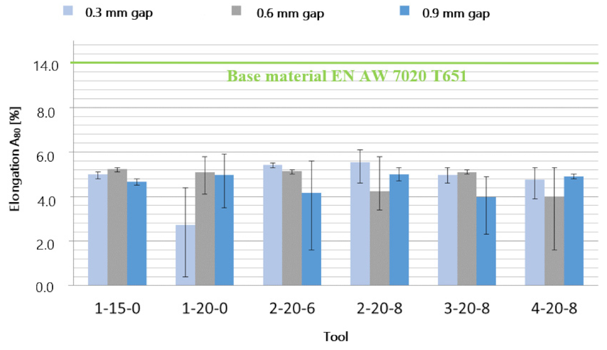
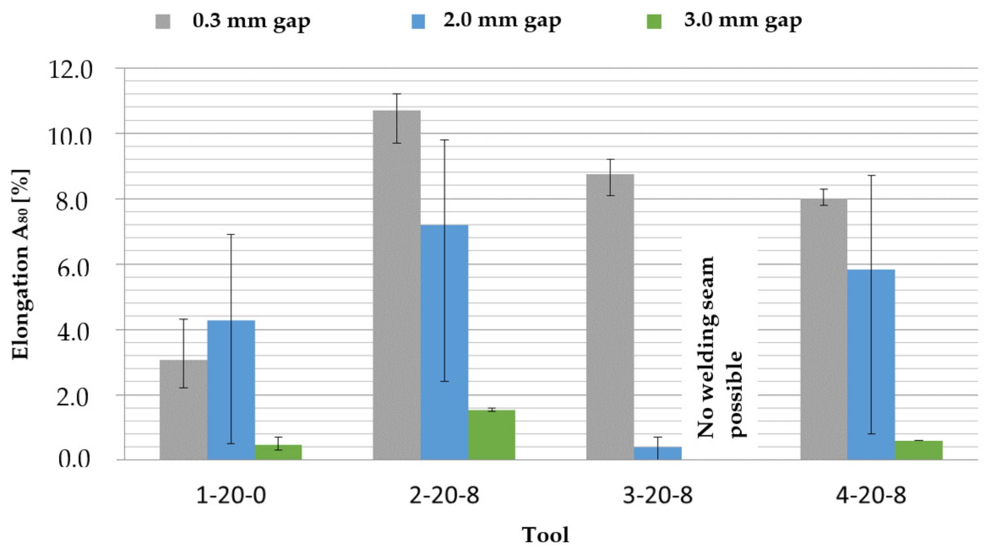
The tensile test, which is based on the welding with tool 2-20-8, suggests a more ductile behaviour in the area of the welding seam. This is confirmed by looking at the elongation at break
,
Figure 14. The elongation
indicates the achieved extension of the sample from the initial measuring length [
15]. The additional index 80 at elongation at break
identifies the specimen dimensions and indicates the initial measuring length, to which the achieved elongation at break is referred, in mm. The tensile test specimens of the welds of the two-pin tool 2-20-8 achieve the highest elongation at break values of about 11%. These are comparable with those of the evaluated base material, whose reference value is shown as the green line in
Figure 14. Moreover, the welding seams welded with the multi-pin tools 3-20-8 and 4-20-8 still show good elongation at break of more than 8%. In comparison, tool 2-20-6 with a smaller pin circle diameter does not reach even half of these values.
It has been shown that the multi-pin tools 2-20-8, 3-20-8 and 4-20-8 show significantly higher and more constant elongations at break compared to the single-pin tools. However, the minimum elongation at break of 15% required by DIN EN 485-2 for the nominal thickness of the material of 4 mm was not achieved in any of the welds. The tensile test specimens of the base material also only show a lower elongation at break of 11.3%.
Cross Sections
Based on the cross sections produced for each welding seam, internal welding seam irregularities could be identified, and the dimensions of the respective seam and the welding seam zones could be measured.
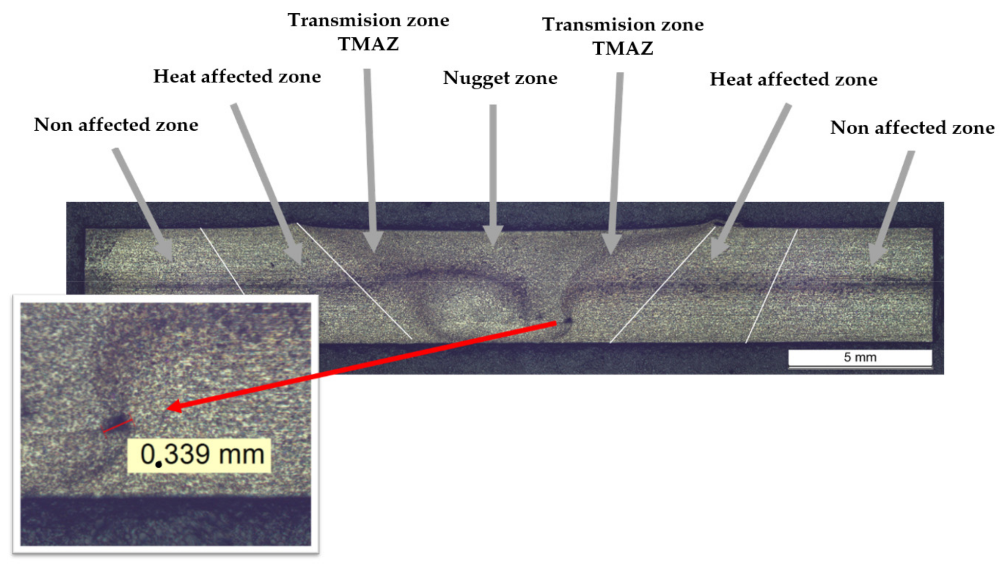
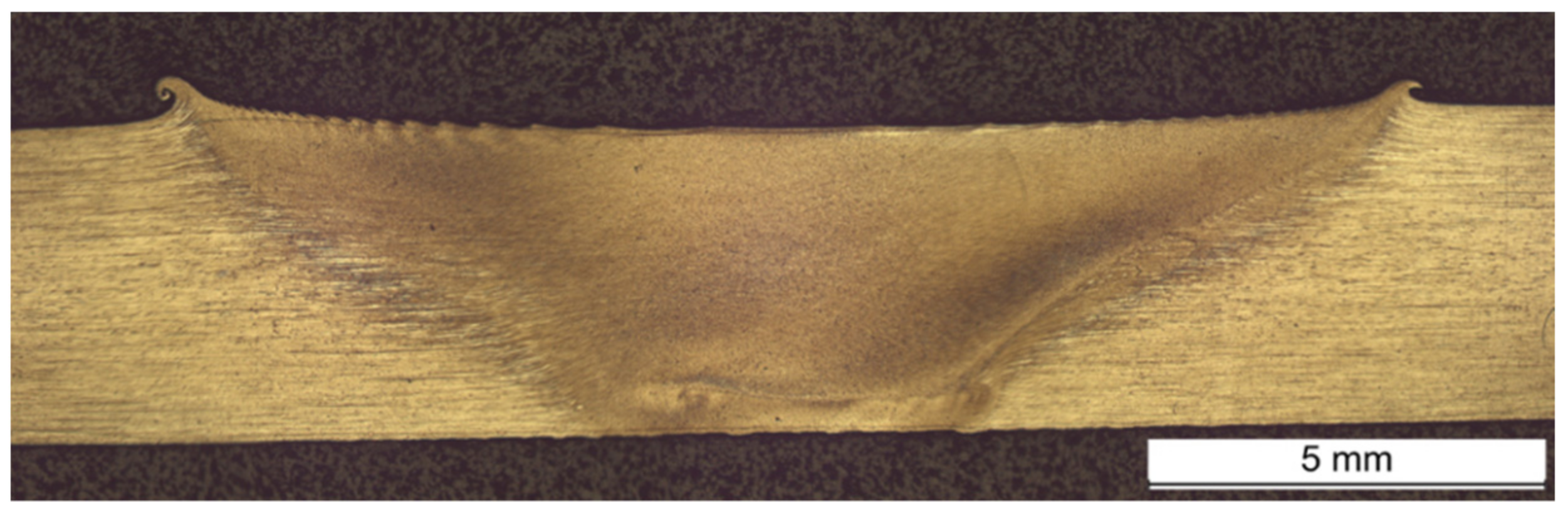
Figure 15 shows the cross section of a weld using tool 1-15-0. In the cross sections, the welding seam zones can be clearly recognised and are additionally labelled in the Figure.
The welded joint shown in
Figure 15 was welded with a joint gap of 0.6 mm or 15% of the sheet thickness. The base material shows a dark discoloration on the horizontal plane. This discoloration occurs partly in rolled materials, such as the EN AW 5083 H111 shown. It should be explicitly noted that this is not a material defect. On closer inspection of the micro section, it is noticeable that even at this joint gap width, a cavity with a diameter of about 0.3 mm can be seen in the welded joint. This probably represents a tube pore, which, according to the DIN EN ISO 25239-5 standard, would only be classified as impermissible from a diameter of about 0.8 mm and, therefore, does not represent a welding seam defect. Parallel to this, the diagram in
Figure 12 shows that the tensile strength
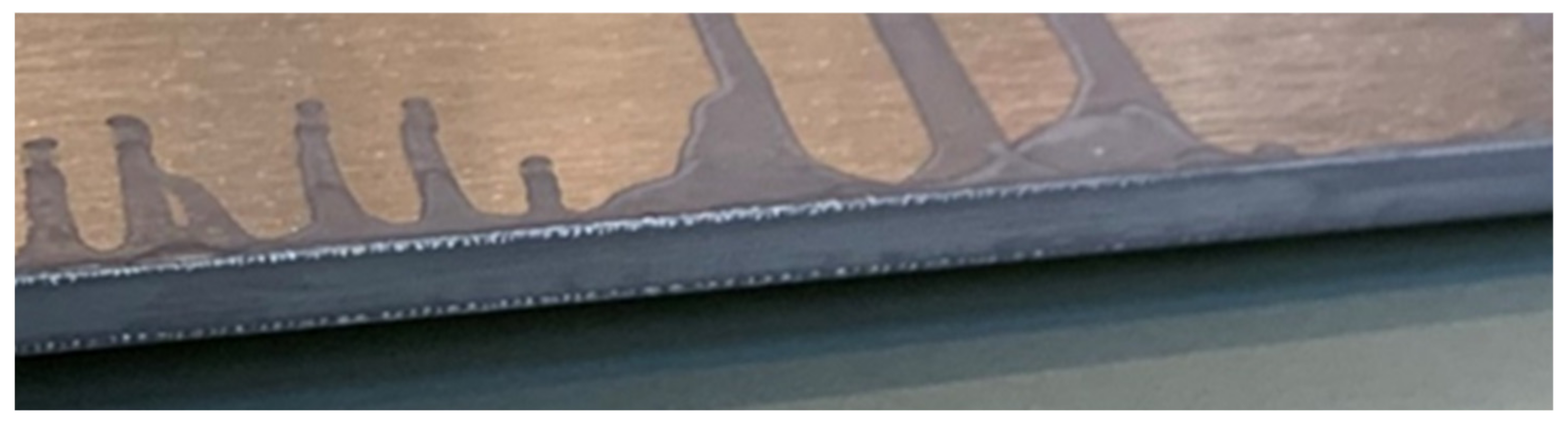
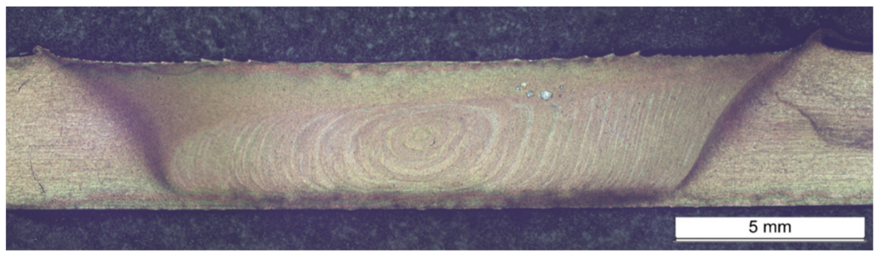
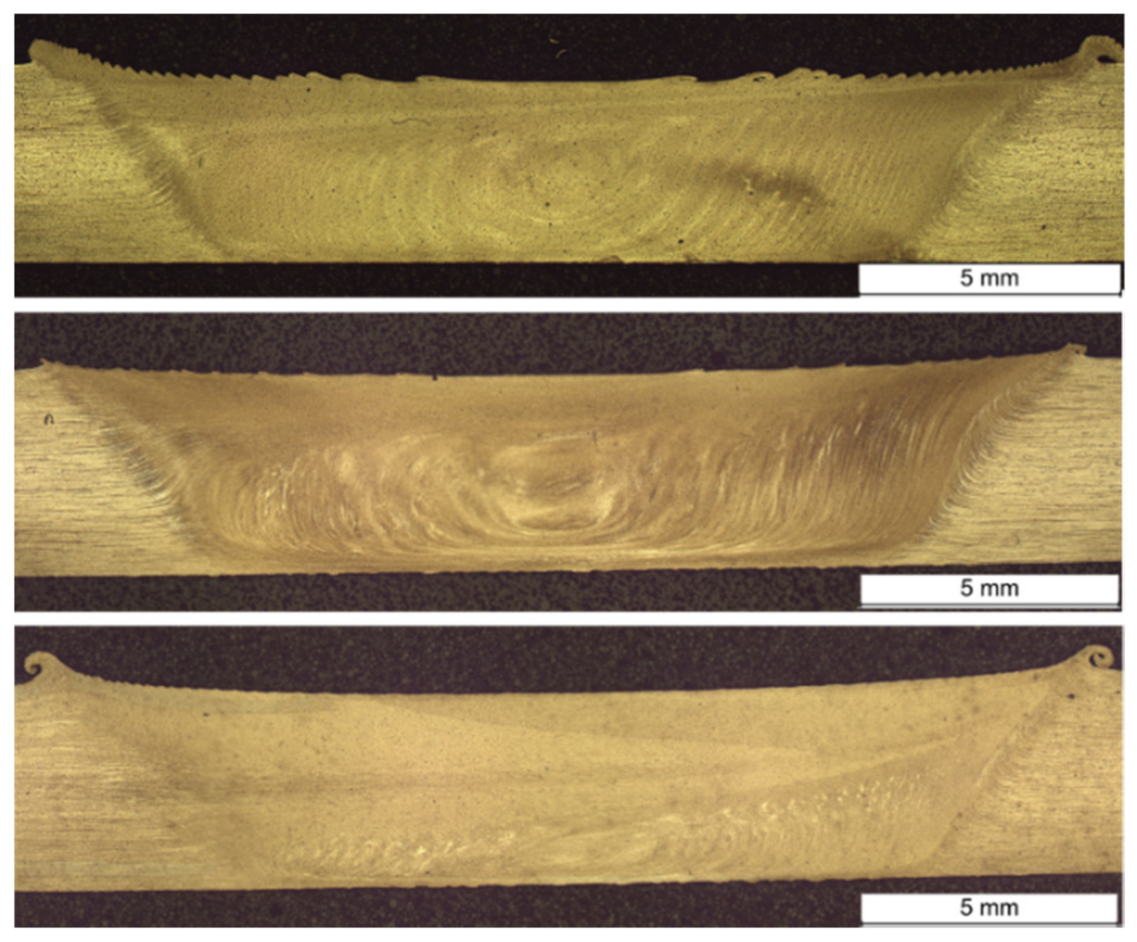
decreases slightly from this joint gap width for the welds of tool 1-15-0 as the irregularity occurs. In comparison to this, no irregularities in the welding seam area were detected up to a joining gap of 0.9 mm, for example, when welding with the two-pin tool 2-20-8, with which the highest and most constant tensile strengths were achieved in the welding tests. The cross section of a welding seam with this tool and a joining gap of 0.9 mm is shown in
Figure 16. Compared to welding with the single-pin tool, a layered structure of the stirring zone is clearly visible here. In principle, the individual layers can be described as concentric ovals around the centre of the weld. The layered structure is mainly visible in the lower welding seam area.
Upon evaluation of the welding seams on the basis of the cross sections, it can be ascertained that, in contrast to single pin tools, a welding seam without irregularities can be produced with the two-pin tools, even with a joint gap of 0.9 mm. Similar to the two-pin tool 2-20-8, the three-pin tool 3-20-8 can also produce flawless welding seams up to a joint gap width of 0.9 mm, however, the tensile strength of the joint is lower than that of the two-pin tool. Nevertheless, the fluctuations of the tensile strength values are smaller when using a three-pin tool. With the four-pin tool 4-20-8, small irregularities can occur in the lower right-hand area of the welding seam, comparable to the single-pin tool 1-15-0 (see
Figure 15), but according to DIN EN ISO 25239-5 these are not to be classified as impermissible.
Hardness Measurement
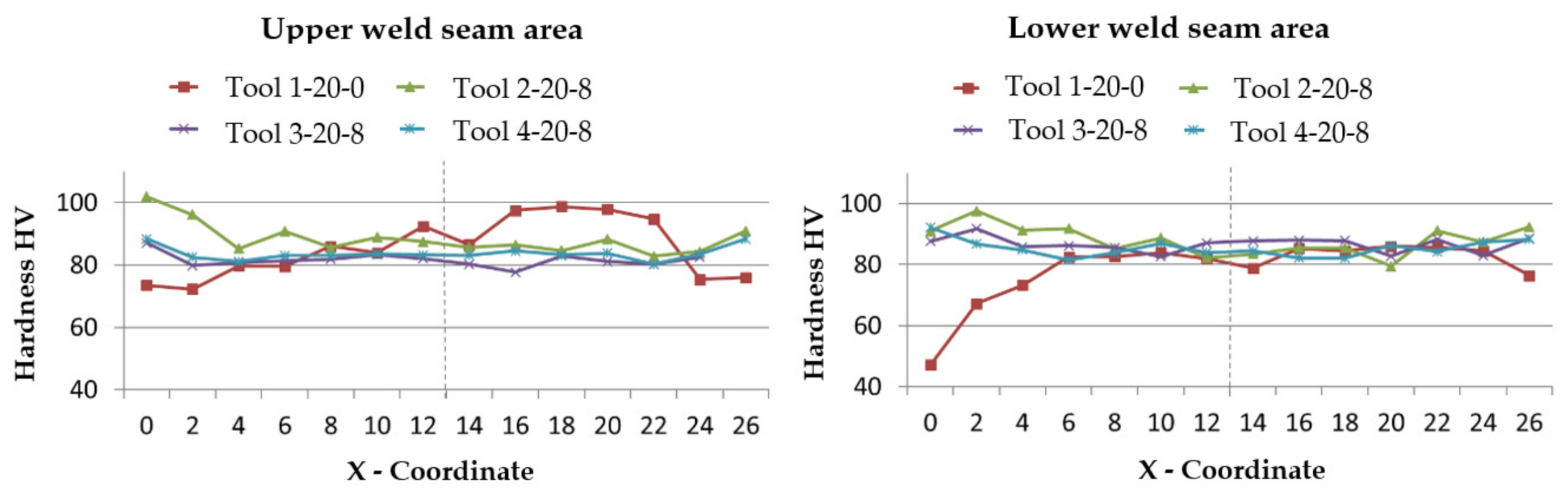
In order to highlight a possible influence of the multi-pin arrangement on the hardness profile across the width of the welding seam, hardness measurements according to Vickers were carried out and the hardness HV is measured. For this purpose, test points were arranged on a line and placed at a distance of 2 mm over the width of the cross sections. The distance between the two hardness measurement lines is also 2 mm apart, enabling the measurements to be carried out in both the upper and lower welding seam areas. The results of the hardness measurements are shown in
Figure 17. The centre of the welding seam is shown in the diagrams as a dashed line.
By means of the hardness profiles, it can be seen that the multi-pin arrangement has no significant influence on the hardness HV within the welding seam, since the hardness in the welding seam area is at a similar level for all the welds shown. Furthermore, no clear difference between the hardness values in the upper and lower welding seam area can be seen. However, it can be clearly seen from the profiles that the hardness in the right and left area of the cross section of the welds welded with the single-pin tool is lower than in the centre of the welding seam. In contrast, the hardness increases in these areas of the welds with the multi-pin tools, especially in the upper area of the welding seam. This tendency is also slightly present in the lower welding seam area with the multi-pin tools.
The different hardness profiles for the single-pin and multi-pin tools can be attributed to the different dimensions of the tools. In the case of the multi-pin tools, the resulting pin diameter is approximately 2.6 times that of the single-pin tool. This results in different dimensions of the different welding seam zones, which is also confirmed by the hardness measurements. Accordingly, the multi-pin tools form a considerably wider area of the stirring zone.
Bending Test
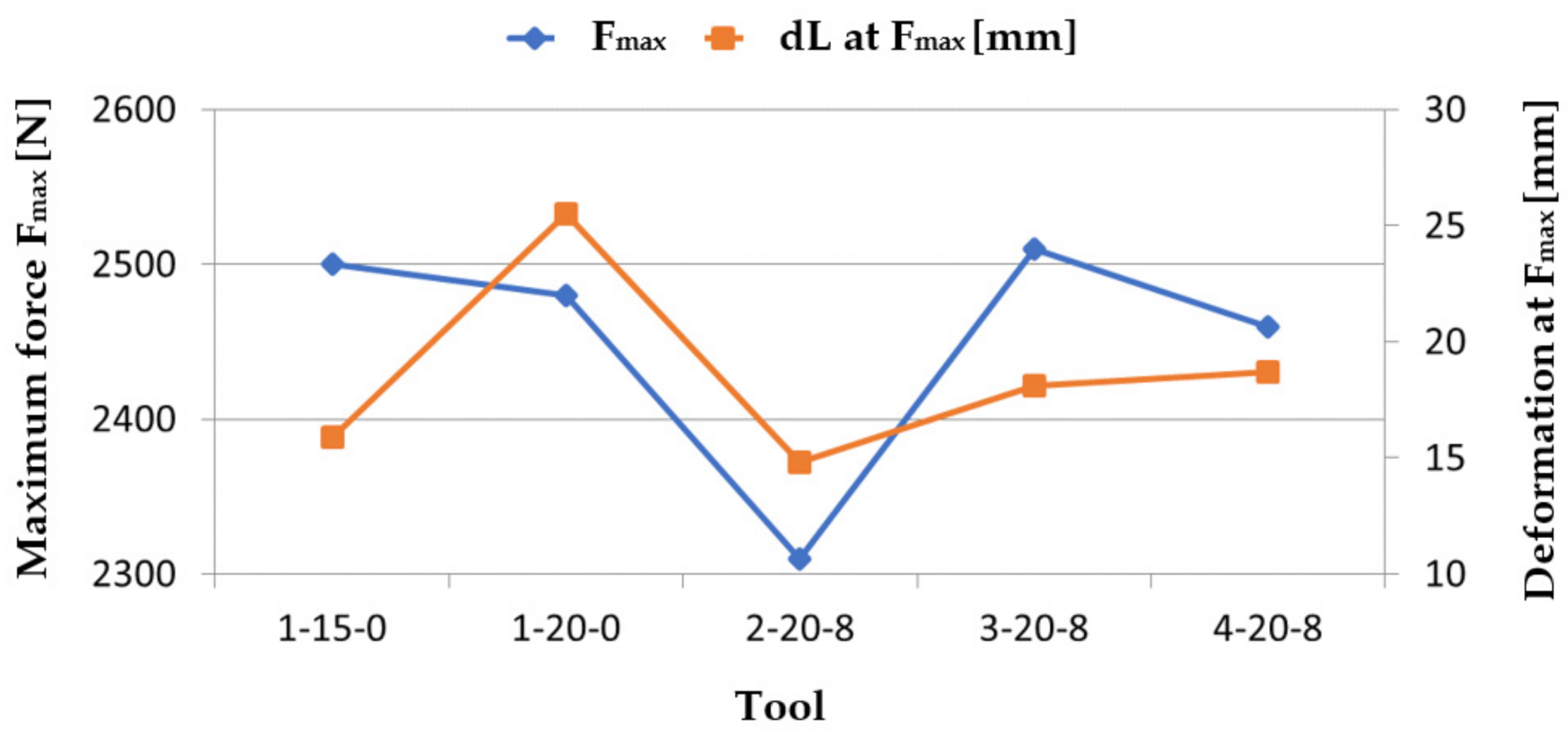
This section deals with the results of the comparative three-point bending test on welds welded with a joint gap of 0.9 mm. The welds with smaller joint gap widths are not considered due to the fact that the gap bridgeability is the main focus of the tests. The bending test is used to highlight the welding seam properties under an applied bending stress by means of a test stamp. For this purpose, the bending samples are placed on two support rollers. The maximum bending force which can be absorbed by the welding seam under bending stress and the distance travelled by the test stamp used at this force can be stated as characteristic values of this test, which are included in the following evaluation. As the force opposing the test stamp decreases again after the maximum force has been reached, it can be assumed that the bending sample begins to crack at the maximum force reached. The distance covered by the test stamp up to this force can, thus, be used as a characteristic value for the deformation capacity of the bending sample under bending stress.
Figure 18 shows that weldment with tool 2-20-8 has the highest maximum bending force
. The welding seams produced with this tool have also shown the best properties in the other tests so far in the evaluation of the test welds. A similar maximum bending force and the corresponding deformation is achieved by welding tool 1-15-0, the lowest values were achieved by tool 1-20-0.
Although the welds with the multi-pin tools 3-20-8 and 4-20-8 have lower maximum forces, these two bending samples show the highest deformations until the maximum force is reached. This suggests that the welding seam can be further deformed without the occurrence of a defect but can still absorb lower forces. The lowest values in relation to the maximum force and the deformation at this bending force are shown by welding with tool 1-20-0, for which the tensile strength and the elongation at break were already low.


