Article

High-Strain Deformation and Spallation Strength of 09CrNi2MoCu Steel Obtained by Direct Laser Deposition

by
Olga Klimova-Korsmik
1,2,*,
Gleb Turichin
1,3,
Ruslan Mendagaliyev
1,3,*,
Sergey Razorenov
2,4,
Gennady Garkushin
4,
Andrey Savinykh
4 and
Rudolf Korsmik
1,3
1
World-Class Research Center “Advanced Digital Technologies”, St. Petersburg State Marine Technical University, 190121 St. Petersburg, Russia
2
Scientific and Educational Center “Additive Technologies”, National Research Tomsk State University, 634050 Tomsk, Russia
3
Institute of Metallurgy, Mechanical Engineering and Transport, Peter the Great St. Petersburg Polytechnic University, 195251 St. Petersburg, Russia
4
Department of Extreme States of Matter, Institute of Problems of Chemical Physics of RAS, 142432 Chernogolovka, Russia
*
Authors to whom correspondence should be addressed.
Metals 2021, 11(8), 1305; https://doi.org/10.3390/met11081305
Submission received: 30 June 2021 / Revised: 12 August 2021 / Accepted: 13 August 2021 / Published: 18 August 2021
(This article belongs to the Special Issue Laser Processing of Metals and Alloys)

Abstract

:
In this work, the critical fracture stresses during spalling of high-strength steel 09CrNi2MoCu samples obtained by direct laser deposition (DLD) were measured under shock compression of up to ~5.5 GPa. The microstructure and mechanical properties of DLD steel samples in the initial state and after heat treatment were studied and compared to traditional hot rolled one. The microstructural features of steel before and after heat treatment were revealed. The heat treatment modes of the deposit specimens on their strength properties under both static and dynamic loads have been investigated. The spall strength of the deposited specimens is somewhat lower than the strength of steel specimens after hot rolling regardless of their heat treatment. The minimum elastic limit of elasticity is exhibited by the deposit specimens. After heat treatment of the deposit samples, the elastic limit increases and approximately doubles. Subsequent heat treatment in the form of hardening and tempering allows obtaining strength properties under Hugoniot loads in traditional hot-rolled products.

1. Introduction

Due to extreme conditions of welded structures operation, such as icebreaker hulls, elements of offshore drilling rigs and power reactors at high latitudes, it is necessary to create cold-resistant steels with high strength, ductility, brittle and impact fracture. Currently, their use is becoming more urgent in connection with the acceleration of the development of natural resources of the circumpolar regions and the Russian Arctic shelf. Improving the strength characteristics of special steels by various methods continues to be an urgent task of metallurgy and material science. One of the most Hugoniot all developed innovative technologies for the manufacture of structural materials in metallurgy include additive technologies [1,2,3,4] that make it possible to obtain volumetric parts of complex shapes. Their rapid development has resulted in the creation of laser additive technologies for the manufacture of materials and products. The most common of them include direct laser deposition (DLD—Direct Laser Deposition; LMD—Laser Metal Deposition; or DMD—Direct Metal Deposition) [5,6] and selective laser fusion (SLM—Selective Laser Melting) [7,8] and their varieties. The peculiarity of the DLD method is that the initial material in the form of a powder and energy for its fusion in the form of directed laser deposition is simultaneously supplied to the place of construction of the product. Numerous studies of the physical and mechanical properties of products manufactured by additive technologies have shown that almost all of them demonstrate high strength compared to traditional technologies [9,10,11,12].
As for traditional metals and alloys, heat treatment of additive materials can greatly change their mechanical characteristics [13]. In most cases, measurements of their strength properties were carried out under static or quasi-static loads by using standard methods. However, the extreme operating conditions of products made of additive materials imply the possibility of exposure to intense impulse and shock loads. Then, numerical modeling of the high-rate deformation and fracture processes, when the strain rate exceeds 104 s−1, is carried out in order to predict the behavior of the products under these conditions. In turn, this requires experimental information on strength characteristics for constructing the constitutive relationships; the Hugoniot strength and elastic-plastic properties of additive technology products in a wide range of parameters of intense pulsed loads are needed. Such measurements under shock-wave load of metals and alloys obtained by additive methods are few in number.
Measurements of the Hugoniot elastic limit (HEL) and Hugoniot tensile strength under conditions of spall fracture (spall strength) for addictive technologies products from the aluminum alloy AlSi10Mg [14,15] and stainless steel 304L [16] revealed a noticeable increase in these characteristics in comparison with their counterparts obtained by using traditional technologies.
In this work, samples were obtained by DLD from cold-resistant steel 09CrNi2MoCu. The subsequent heat treatment of the deposit samples was carried out. The microstructure of the deposit samples, heat treatment and initial rolled samples were investigated. Static tensile mechanical tests have been carried out. The critical fracture stresses during spalling and the Hugoniot elastic limit of specimens, obtained by DLD, under shock compression up to ~5.5 GPa depending on their preliminary heat treatment have been measured. For comparison, similar experiments were performed on samples of this steel obtained by hot rolling.

2. Materials and Methods

The samples of 09CrNi2MoCu steel were produced on a technological complex of direct laser deposition. Its main components are an industrial robot M20iB/25 (Fanuc, Oshino-mura, Japan), LS-3 ytterbium fiber laser (IPG Photonics, Oxford, MA, USA), a FLW D30 laser focusing head (IPG Photonics, Oxford, MA, USA) with a SO12 cladding nozzle (Fraunhofer IWS, Dresden, Germany) and a Metco Twin 150 powder feeder (Oerlikon, Freienbach, Switzerland).
The workpieces were prepared by direct laser deposition in a sealed chamber with a controlled atmosphere of a protective gas at a pressure of 2–3 Mbar. High-purity argon was used as gas atmosphere or protective gas; the residual oxygen content in the chamber did not exceed 1000 ppm. We used a 09CrNi2MoCu grade powder with a fraction of 45–160 μm, which has a high sphericity index ψ = 0.9528. The surfacing process was carried out at a laser power of p = 2000–2300 W and a nozzle velocity of V = 25 mm/s [5]. As a material for deposition, we used 09CrNi2MoCu grade bainite-martensitic powder (Figure 1). The chemical composition of 09CrNi2MoCu steel powder is shown in Table 1.
The 09CrNi2MoCu steel billets deposit by the DLD method were heat treated in a programmable muffle furnace SNOL 30/1300 (AB UMEGA-GROUP, Utena, Lithuania), and the heat treatment modes are presented in Table 2. The heat treatment of 09CrNi2MoCu steel, developed at the Central Research Institute of «KM Prometey» [17,18], was chosen for the study. In order to verify the developed modes, heat treatment was carried out on the deposition samples for further studies.
The original and heat-treated workpieces were used to create samples for metallographic analysis by molding them in a phenolic compound, grinding and then polishing. The structure of these samples was revealed by using the Klemm’s in 50 mL of a concentrated solution of Na2S2O3 + 1 g of Na2S2O5, with a holding time of 3–5 min. Microstructural studies were performed by light optical microscopy using an inverted Leica DMi8 (Leica Microsystems, Wetzlar, Germany) microscope equipped with an «Axalit» image analyzer (Axalit, Moscow, Russia). Research of chemical composition and chemical elements distribution was performed by using a scanning electron microscope Tescan Mira3 with EDS analysis Advanced UltimMax 65 (Tescan, Brno, Czech Republic).
The content of residual austenite in the samples was determined by the method based on etching with Klemm’s reagent and image analysis using the program «ImageJ». The level of contrast in shades of gray is sufficient for conducting binarization at a given threshold of brightness and for determining the volume fraction of residual austenite according to ASTM E1245 in an automated mode.
Microhardness measurements were performed on an FM-310 (Future Tech, Kawasaki, Japan) series microhardness tester with a 300 g Vickers load and a «Thixomet Pro» image analyzer (Thixomet, St. Petersburg, Russia). Mechanical tests were performed on a universal testing machine, Zwick Roell Z100 (Zwick Roell, Ulm, Germany), with a longitudinal strain gauge of 100 kN for tensile testing of metals, with two specimens for each direction.
In order to study the effect of heat treatment of steel samples by the DLD method on its strength characteristics at strain rates of ~105 s−1, a series of experiments were carried out to record the full velocity profiles of the free surface of the samples in the process of their shock compression. One of the widely used methods for studying the behavior of samples under shock-wave loading is based on measurements of the evolution (shape change) of the shock wave as spreading deep into the sample when the pulse duration is microseconds or less, and the strain rates exceed 104 s−1. The shape of the shock wave at the exit from the sample reflects all the processes occurring inside the loaded material, and it is determined by the processes of elastoplastic deformation and fracture in the material [19,20]. In this work, we measured the Hugoniot (spall) strength and Hugoniot elastic limit under shock compression up to 5.5 GPa for all types of samples. Shock wave experiments were carried out using the equipment of the Moscow Regional Explosive Center for Collective Use of the Russian Academy of Sciences (AAAA19-119071190040-5). Specimens ~2 mm thick for shock-wave experiments were cut from additive steel workpieces, which were 10 mm × 10 mm × 20 mm bars in size with a clearly visible direction of surfacing. The samples were cut by the electroerosive method perpendicular to the direction of surfacing in which their planes were practically parallel.
The samples were loaded by impact of a flat aluminum plate 0.4 ± 0.02 mm thick and accelerated by explosive devices to a velocity of 630 ± 30 m/s [19]. A schematic of shock-wave experiments is shown in Figure 2. Due to a fairly significant scatter of the impactor velocity, the intensity of the compression wave in these experiments varied in the range 4.1–5.5 GPa, and the strain rate before fracture was on average ~1.9 × 10⁵ s−1. The experiments were carried out in air at room temperature of the samples. The one-dimensionality of the loading process during the entire required recording time was ensured by a sufficiently large ratio of the specimen thickness and their linear dimensions (approximately 1:5). In all experiments, full velocity profiles were recorded by using a Doppler laser interferometric velocimeter VISAR (Institute of Problems of Chemical Physics of RAS, Chernogolovka, Russia) [21] with a temporal resolution of about 1 ns and a spatial resolution of ~0.01 mm2.

3. Results and Discussion

3.1. Microstructure and Mechanical Properties under Static Loads

In order to identify residual austenite and other bainite phases, we used color etching in Klemm’s reagent. Figure 3 shows the microstructure of the samples in the rolled state and the microstructure of the samples after deposition and after different heat treatment obtained with an optical microscope.
The microstructures of the rolled sample and the sample after heat treatment under the T3 mode (Figure 3a,d) are almost identical and consist of granular bainite. The rolled sample has a banded structure, and the residual austenite is 0.68%. In the samples obtained by direct laser deposition (Figure 3b), the microstructure consists of bainite ferrite. In the samples after annealing (Figure 3c), the microstructure is a mixture of granular bainite, and the structure is a mixture of bainite ferrite and granular bainite after quenching and tempering of the deposit sample (Figure 3e). Since the residual austenite content is less than 1% for the determination by X-ray phase analysis, it is possible to classify structures by color tracing [22].
In order to determine the phase composition of steel in detail, the microstructure was studied with an electron microscope. Figure 4 shows the microstructure of the samples obtained using a scanning electron microscope in various processing conditions.
The microstructure after rolling is granular bainite (Figure 4a) with retained austenite content. After heat treatment according to T3 mode (Figure 4d), the microstructure consists of granular bainite with martensite and retained austenite (M/A) phase. In the sample after direct laser deposition (Figure 4b), the microstructure consists of bainitic ferrite and tertiary cementite at the grain boundaries. In the samples after annealing (Figure 4c), the microstructure is a mixture of bainitic ferrite, and after quenching and tempering of the deposit sample (Figure 4e), the structure is a mixture of bainitic ferrite and ferrite [23,24].
The atom mappings of Fe, Cr, Ni, Mo and Si in an analyzed section are shown in Figure 5. The atoms of Fe, Cr, Ni and Si are evenly distributed within the scanned area. Mo segregation occurs in the rolled sample and in the deposited sample. After heat treatment at T3, the mode molybdenum is evenly distributed.
The role of Mo is very important in alloys. Molybdenum segregates along grain boundaries and combines with P, C, S and B. The addition of Mo reduces the grain boundary segregation of other elements. Grain boundary segregation plays an important role in the mechanical properties of the samples. In order to evaluate the mechanical properties, tensile and microhardness tests were performed. The results of these tests are shown in Table 3.
The average microhardness of rolled samples is 200–220 HV with high tensile strength. The microhardness of the sample deposit by DLD in the initial state is 205–280 HV with a wide scatter of values, which indicates a certain inhomogeneity of the structural components. Table 3 show the results of measurements of the mechanical characteristics of steel samples after various heat treatment.
After heat treatment of the sample deposit by the DLD method according to the T2 mode, its microhardness decreased to ~180–200 HV together with the ultimate strength, and the relative elongation increased to 25.9%. Heat treatment mode T3 results in an increase in the microhardness of the additive steel up to 260–280 HV, while its ultimate strength increased. Heat treatment according to the T4 mode resulted in a slight decrease in the microhardness (240–260 HV) and mechanical strength characteristics of the steel samples in comparison with the T3 mode. Thus, metallographic analysis of steel samples after various heat treatment and measurements of strength characteristics under static loads showed that the optimal microstructure with high mechanical properties is granular bainite in steel samples obtained by the DLD method, without any heat treatment. Despite the large spread of microhardness (205–280 HV), the samples deposited by DLD without additional heat treatment have an optimal balance of ultimate strength of 783.6 MPa and relative elongation of 18.1% than compared to heat-treated samples.

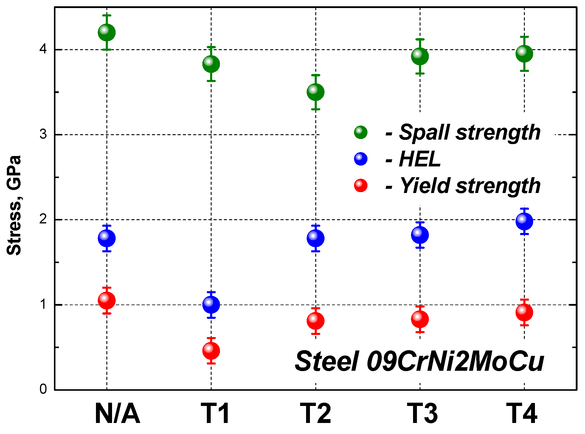
3.2. Strength Properties under Shock Loading

Figure 6 shows the velocity profiles of the free surface of 09CrNi2MoCu steel samples obtained by the DLD method and, for comparison, the velocity profile of the same steel obtained by the traditional hot rolling steel. The wave profiles reflect all the features of the loading process in the shock compression: unloading cycle under conditions of spall fracture of the specimen. The front of the shock wave upon reaching the surface of the sample has the two following wave configurations: an elastic precursor and a plastic compression wave. An elastic precursor propagates through the sample with the longitudinal speed of sound, and the amplitude of elastic precursor is determined by the elastic limit of the material. The stress corresponding to the Hugoniot elastic limit of the material σHEL is calculated from the amplitude of the elastic compression wave uHEL measured from the surface velocity profile as σHEL = ρ0CluHEL/2 [23], where Cl is the longitudinal speed of sound. The longitudinal speed of sound measured by the ultrasonic method for additive and hot-rolled steel samples is somewhat different and amounts to the following, respectively: Cl_add—5500 ± 30 m/s; and Cl_orig—5710 ± 20 m/s. The values Y (σT) of the Hugoniot yield strength under conditions of one-dimensional deformation are calculated from the following ratio:
σ T = 3 / 2 σ H E L ( 1 c b 2 / c l 2 )
where Cb is the bulk speed of sound that is equal to 4580 ± 20 m/s.
Moreover, there is a smooth transition from elastic to plastic compression of the material associated with the hardening of the material. The amplitude of the plastic compression wave is determined by the bulk compressibility of the material, and its velocity at moderate pressures is close to the bulk speed of sound. The maximum pressure in the compression wave is calculated as Pmax = ρ0Usufs, where ρ0 is the density of the samples, Us is the shock wave velocity and ufs is the particle velocity determined from the velocity profiles. Since the density of steel samples obtained by different technologies did not practically change after heat treatment, in the analysis of experimental data its shock adiabat was used in the form of a linear relationship between the shock wave velocity Us and the particle velocity up: Us = 4.58 + 1.49up.
Behind the shock wave, as can be observed from Figure 6, a rarefaction wave emerges on the sample surface, reducing its velocity. Since the thickness of the sample in these experiments were chosen to be approximately five times greater than the thickness of the impactor, with this ratio of thicknesses near the free surface, the shock wave already begins to decay under the action of the unloading wave that overtakes it, and the compression pulse has a triangular shape. The first minimum of the velocity coincides in time with the formation of a fracture zone inside the sample in the form of a spall crack, when tensile stresses are generated inside the sample during the interaction of the incident and reflected from the free surface rarefaction waves, which exceed the strength of the sample. At the moment of spalling, tensile stresses relax from a value equal to the critical tensile stresses (spall strength of the material) to zero, as a result of which a compression wave and a spall pulse emergeon the free surface of the sample. The value of the decrease in the surface velocity Δufs (Figure 6) from its maximum to the first minimum before the front of the spall pulse is proportional to the spall strength of the material σsp. In the linear (acoustic) approximation, the value of the spall strength is determined as σsp = 1/2ρ0Cb (Δufs+ δ), where δ is the correction for the distortion of the velocity profile due to the difference in the speed of the front of the spall pulse, equal to Cl, and the speed of the plastic part of the incident unloading wave in front of it, moving with the bulk speed of sound (Cb) [25].
Reverberations of the spall pulse in the spall plate result in surface velocity oscillations, recorded on the profile as damped velocity oscillations. From the time of one oscillation of the spall pulse Δt in the spall plate, one can determine its thickness as hsp = ClΔt/2. The deformation rate is actually the rate of expansion of the substance in the rarefaction wave and is equal to the following:
V ˙ V 0 = u ˙ f s r 2 c b
where u ˙ f s r is the rate of decay of the free surface velocity in the unloading wave before spalling, determined from the wave profile.
Although all waveforms are similar, there are some quantitative and qualitative differences. Figure 6 shows that both the amplitude of the elastic precursor uHEL and the decay of the velocity before spalling Δufs differ for different samples, depending on their manufacturing technology and heat treatment. For hot-rolled specimens and DLD specimens, after heat treatment according to the T2 and T3 modes, a rapid decay of the amplitude of subsequent oscillations of the spall pulse in the spall plate is observed against the background of a strong decrease in their average velocity. This reduction in velocity usually occurs with ductile metals and alloys, such as copper, aluminum, stainless steel and the like, at short compression pulses [19] and is associated with a delay in the complete separation of the spall plate, which remains connected with main plate for some time. In hot-rolled samples, the spall pulse decays almost immediately after the first exit to the free surface of the sample, which may be associated with the appearance of a strongly developed spall surface during internal rupture of the sample. In these experiments, due to their peculiarity, it was not possible to save the samples for the subsequent metallographic analysis of the spall fracture zone. On the wave velocity profile for the samples after heat treatment according to the T1 mode, a sharp spall pulse of sufficiently large amplitude is also observed, followed by a strong decay of the amplitude of the velocity oscillations, but the overall decrease in the surface velocity is not so significant. In the case of samples after heat treatment in the T4 mode, the picture is somewhat different. A strong spall impulse and its multiple reflections with a slight attenuation of the oscillation amplitude are recorded on the profile; their average velocity remains almost unchanged. This means that the formed spall surfaces in experiments with these samples have a lower roughness, and the spall plate is almost immediately separated from the main sample. This type of wave profile is usually observed for high-strength materials—high-alloy steels, titanium alloys, tantalum, etc. [26]—which demonstrate the quasi-brittle nature of spalling fracture.
Figure 7 and Table 4 show the calculation results based on processing the wave profiles of the Hugoniot elastic limit, yield strength and spall strength of 09CrNi2MoCu steel samples of all types.
The DLD steel samples in the initial state without heat treatment have the minimum Hugoniot elastic limit. Subsequent heat treatment of DLD specimens in all cases results in its growth by 75–97% to the level of elastic limit of hot-rolled samples. Maximum tensile stresses are realized during spall fracture of hot-rolled samples. The spall strength of the original additive specimen without heat treatment is about 9% lower, and the heat treatment of the DLD specimens according to the T2 mode further reduces it by about 17%. Heat treatment in other modes results in its slight increase; however, its values remain somewhat lower than the strength of hot-rolled samples. Full heat treatment T3 results in the values of the Hugoniot elastic limit and the spall strength of steel, comparable to the values of these characteristics of the samples after rolling.
It should be noted that in static measurements, the minimum tensile strength of the DLD specimens σB, as well as the yield stress σ0.2, is also demonstrated by the samples subjected to heat treatment according to the T2 mode. In all cases, with the exception of measurements on DLD specimens without heat treatment, the Hugoniot yield point is 7–50% higher than its values obtained under static load. The static yield point for the original DLD specimens is about 40% higher than the Hugoniot one. The critical fracture stresses during spalling are 4–5 times higher than the fracture stresses during static tension. Such a large difference is determined by the strong dependence of tensile stresses on the strain rate [26,27]. While the deformation rate did not exceed 3.5 mm/min in static measurements, it was about 7 orders of magnitude higherin shock-wave experiments.

4. Conclusions

For the first time, measurements of the mechanical characteristics of high-strength alloyed cold-resistant steel 09CrNi2MoCu with martensitic-bainitic structure, after impact compression up to 5.5 GPa, have been carried out. By analyzing the full wave profiles, the chipping strength and Hugoniot elasticity limit of steel specimens obtained by additive technology by direct laser deposition in the initial state and after their subsequent heat treatment were measured. For comparison, similar experiments were carried out with samples of the same hot-rolled steel obtained by conventional technology. The ambiguous effects of different heat treatment modes of DLD specimens on their strength properties under both static and shock loads were revealed. The Hugoniotic strength of steel specimens obtained by the conventional method is slightly higher than that of additive manufacturing specimens, regardless of their heat treatment. The Hugoniot elastic limit of the two types of steel can be considered about the same within the range of measurements, except for the samples with additives without heat treatment in which its measured value is about half as high. The microstructural components and features of steel were investigated. The influence of mechanical properties of impact characteristics with microstructural features of this steel was studied.

Author Contributions

Conceptualization, S.R., G.T. and O.K.-K.; methodology, A.S., R.M. and R.K.; validation, S.R. and O.K.-K.; writing—original draft preparation, R.M. and A.S.; writing—review and editing, S.R. and G.G.; visualization, R.K. and R.M.; supervision, S.R. and G.T. All authors have read and agreed to the published version of the manuscript.

Funding

This work was financially supported by the Ministry of Science and Higher Education of the Russian Federation within the framework of the “World-class Science Center” program: Advanced digital technologies (Grant Agreement No. 075-15-2020-903).

Institutional Review Board Statement

Not applicable.

Informed Consent Statement

Not applicable.

Data Availability Statement

Not applicable.

Conflicts of Interest

The authors declare no conflict of interest.

References

  1. Kuznetsov, M.; Turichin, G.; Silevich, V.; Ochkasov, V.; Sorokin, A. Research of technological possibility of increasing erosion resistance rotor blade using laser cladding. Procedia Manuf. 2019, 36, 163–175. [Google Scholar] [CrossRef]
  2. Mendagaliyev, R.; Turichin, G.A.; Klimova-Korsmik, O.G.; Zotov, O.G.; Eremeev, A.D. Microstructure and Mechanical Properties of Laser Metal Deposited Cold-Resistant Steel for Arctic Application. Procedia Manuf. 2019, 36, 249–255. [Google Scholar] [CrossRef]
  3. Toloui, M.; Militzer, M. Phase field modeling of the simultaneous formation of bainite and ferrite in TRIP steel. Acta Mater. 2018, 144, 786–800. [Google Scholar] [CrossRef]
  4. Korsmik, R.; Tsybulskiy, I.; Rodionov, A.; Klimova-Korsmik, O.; Gogolukhina, M.; Ivanov, S.; Zadykyan, G.; Mendagaliev, R. The approaches to design and manufacturing of large-sized marine machinery parts by direct laser deposition. Procedia CIRP. 2020, 94, 298–303. [Google Scholar] [CrossRef]
  5. Mendagaliyev, R.V.; Zadykyan, G.G.; Davletshin, A.O.; Mukashev, T.; Rashkovets, M. Direct laser deposition of cold-resistant steels for Arctic shelf development. Mater. Today Proc. 2020, 30, 707–711. [Google Scholar] [CrossRef]
  6. Babkin, K.; Zemlyakov, E.; Ivanov, S.; Vildanov, A.; Topalov, I.; Turichin, G. Distortion prediction and compensation in direct laser deposition of large axisymmetric Ti-6Al-4Vpart. Procedia CIRP. 2020, 94, 357–361. [Google Scholar] [CrossRef]
  7. Ponnusamy, P.; Sharma, B.; Masood, S.H.; Rashid, R.R.; Rashid, R.; Palanisamy, S.; Ruan, D. A study of tensile behavior of SLM processed 17-4PH stainless steel. Mater. Today Proc. 2021, 45, 4531–4534. [Google Scholar] [CrossRef]
  8. Roth, C.C.; Tancogne-Dejean, T.; Mohr, D. Plasticity and fracture of cast and SLM AlSi10Mg: High-through put testing and modeling. Addit. Manuf. 2021, 43, 101998. [Google Scholar]
  9. Sklyar, M.O.; Turichin, G.A.; Klimova, O.G.; Zotov, O.G.; Topalov, I.K. Microstructure of 316L stainless steel components produced by direct laser deposition. Steel Transl. 2016, 46, 883–887. [Google Scholar] [CrossRef]
  10. Yao, Y.; Huang, Y.; Chen, B.; Tan, C.; Su, Y.; Feng, J. Influence of processing parameters and heat treatment on the mechanical properties of 18Ni300 manufactured by laser based directed energy deposition. Opt. Laser Technol. 2018, 105, 171–179. [Google Scholar] [CrossRef]
  11. Akbari, M.; Kovacevic, R. An investigation on mechanical and microstructural properties of 316L Sip arts fabricated by a robotized laser/wire direct metal deposition system. Addit. Manuf. 2018, 23, 487–497. [Google Scholar]
  12. Guan, T.; Chen, S.; Chen, X.; Liang, J.; Liu, C.; Wang, M. Effect of laser incident energy on microstructures and mechanical properties of 12CrNi2Y alloy steel by direct laser deposition. J. Mater. Sci. Technol. 2019, 35, 395–402. [Google Scholar] [CrossRef]
  13. Olasolo, M.; Uranga, P.; Rodriguez-Ibabe, J.M.; López, B. Effect of austenite microstructure and cooling rate on transformation characteristics in a low carbon Nb–V microalloyed steel. Mater. Sci. Eng. A 2011, 528, 2559–2569. [Google Scholar] [CrossRef]
  14. Zaretsky, E.; Stern, A.; Frage, N. Dynamic response of AlSi10Mg alloy fabricated by selective laser melting. Mater. Sci. Eng. A 2017, 688, 364–370. [Google Scholar] [CrossRef]
  15. Laurençon, M.; De Resseguier, T.; Loison, D.; Baillargeat, J.; Ngnekou, J.D.; Nadot, Y. Effects of additive manufacturing on the dynamic response of AlSi10Mg to laser shock loading. Mater. Sci. Eng. A 2019, 748, 407–417. [Google Scholar] [CrossRef]
  16. Wise, J.L.; Adams, D.P.; Nishida, E.E.; Song, B.; Maguire, M.C.; Carroll, J.; Reedlunn, B.; Bishop, J.E.; Palmer, T.A. Comparative shock response of additively manufactured versus conventionally wrought 304L stainless steel. AIP Conf. Proc. 2017, 1793, 100015. [Google Scholar]
  17. Golosienko, S.A.; Motovilina, G.D.; Khlusova, E.I. Influence of the structure generated at hardening on properties of high-strength cold-resistant steel after tempering. Mater. Sci. Issues 2008, 1, 32–44. [Google Scholar]
  18. Stchastlivtsev, V.Ì.; Tabatchikova, T.I.; Jakovleva, I.L.; Egorova, L.J.; Vatutin, K.A.; Golosienko, S.A.; Kruglova, A.A.; Khlusova, E.I. Influence of thermo mechanical processing on structure and mechanical properties of ship-building steel 09XH2MDF grade. Mater. Sci. Issues 2008, 1, 20–32. [Google Scholar]
  19. Kanel, G.I.; Razorenov, S.V.; Utkin, A.V.; Fortov, V.E. Shock-Wave Phenomenain Condensed Matter; Yanus, K.M., Ed.; Springer: Berlin/Heidelberg, Germany, 1996; p. 407. [Google Scholar]
  20. Kanel, G.I.; Zaretsky, E.B.; Razorenov, S.V.; Ashitkov, S.I.; Fortov, V.E. Unusual plasticity and strength of metals at ultra-short load durations. Phys. Uspekhi. 2017, 60, 490–508. [Google Scholar] [CrossRef] [Green Version]
  21. Barker, L.M.; Hollenbach, R.E. Laser interferometer for measuring high velocities of any reflecting surface. J. Appl. Phys. 1972, 43, 4669–4675. [Google Scholar] [CrossRef]
  22. Vander Voort, G.F. Color Metallography. Metallogr. Microstruct. 2004, 9, 493–512. [Google Scholar]
  23. Zhou, Y.; Jia, T.; Zhang, X.; Liu, Z.; Misra, R.D.K. Investigation on tempering of granular bainite in an offshore platform steel. Mater. Sci. Eng. A 2015, 626, 352–361. [Google Scholar] [CrossRef]
  24. Li, C.; Duan, R.; Fu, W.; Gao, H.; Wang, D.; Di, X. Improvement of mechanical properties for low carbon ultra-high strength steel strengthened by Cu-rich multistructured precipitation via modification to bainite. Mater. Sci. Eng. A 2021, 817, 141337. [Google Scholar] [CrossRef]
  25. Kanel, G.I. Spall fracture: Methodological aspects, mechanism sand governing factors. Int. J. Fract. 2010, 163, 173–191. [Google Scholar] [CrossRef]
  26. Razorenov, S.V.; Garkushin, G.V.; Ignatova, O.N. Resistance to Dynamic Deformation and Fracture of Tantalum with Different Grain and Defect Structures. Phys. Solid State 2012, 54, 790–797. [Google Scholar] [CrossRef]
  27. Kanel, G.I. Shock Wave in Solid State Physics; Fizmatlit, M., Ed.; CRC Press: Boca Raton, FL, USA, 2018; p. 208. [Google Scholar]
Figure 1. Powder 09CrNi2MoCu: (a) surface of powder particles; (b) histogram of the powder size.
Metals 11 01305 g001
Figure 2. Scheme of experiments on shock-wave loading of the samples.
Metals 11 01305 g002
Figure 3. Microstructure of 09CrNi2MoCu steel in various states: (a) rolled products; (b) T1 (steel in initial state after DLD); (c) T2 (DLD + HT); (d) T3 (DLD + HT); (e) T4 (DLD + HT).
Metals 11 01305 g003
Figure 4. Microstructure of 09CrNi2MoCu steel in various states: (a) rolled products; (b) T1 (steel in initial state after DLD); (c) T2 (DLD + HT); (d) T3 (DLD + HT); (e) T4 (DLD + HT).
Metals 11 01305 g004
Figure 5. Atom mappings from an analyzed section: (a) rolled products; (b) T1 (steel in initial state after DLD); (c) T3 (DLD + HT).
Metals 11 01305 g005
Figure 6. Free surface velocity profiles of 09CrNi2MoCu steel samples obtained by DLD method and hot rolling after different heat treatment.
Metals 11 01305 g006
Figure 7. Hugoniot elastic limit, yield strength and spall strength of steel depending on heat treatment.
Metals 11 01305 g007
Table 1. The chemical composition of the 09CrNi2MoCu powder.
Material GradeCSiMnCrNiMoCuAlFeCa
09CrNi2MoCu Powder0.08–0.110.17–0.370.30–0.700.30–0.701.80–2.200.350.40–0.700.01–0.05Bal.0.03
Table 2. Heat treatment modes of samples.
No. ModeType of TreatmentProcessing Mode
1Rolled productsHot rolling steel
T1Deposition sampleDLD
T2Stress relief annealing1. T = 550 °C, t = 30 min. followed by air cooling;
T3Annealing, quenching and tempering1. Annealing T = 550 °C, t = 30 min, air cooling;
2. Quenching T = 900 °C, t = 2 h, cooling in oil;
3. Tempering T = 600 °C, t = 4 h, cooling in the furnace;
T4Quenching and tempering1. Quenching in oil T = 900 °C, t = 2 h;
2. Tempering T = 600 °C, t = 4 h, cooling in the furnace.
Table 3. Mechanical properties of steel under static loading.
ModeYield Strength (MPa)Ultimate Strength (MPa)Relative Elongation (%)
hot-roiled512.6690.625.4
T1750.5783.618.1
T2405.6574.525.9
T3768.7839.116.4
T4741.5821.415.6
Table 4. Experimental conditions and strength characteristics of steel.
No.hsp, mmhimp, mmPmax, GPa V ˙ / V 0 , 105c−1σHEL, GPaY, GPaσsp, GPahsp, mm
1 (N/A)2.00.435.12.11.780.954.20.39
T12.010.435.122.31.00.463.830.35
T21.970.434.961.71.780.813.50.45
T32.030.465.252.01.820.833.920.42
T41.960.465.692.21.980.913.950.37
Publisher’s Note: MDPI stays neutral with regard to jurisdictional claims in published maps and institutional affiliations.

