
Experimental and Finite Element Study of Polymer Infilled Tube-in-Tube Buckling Restrained Brace


Abstract
:1. Introduction
2. Test Program
2.1. Test Specimens
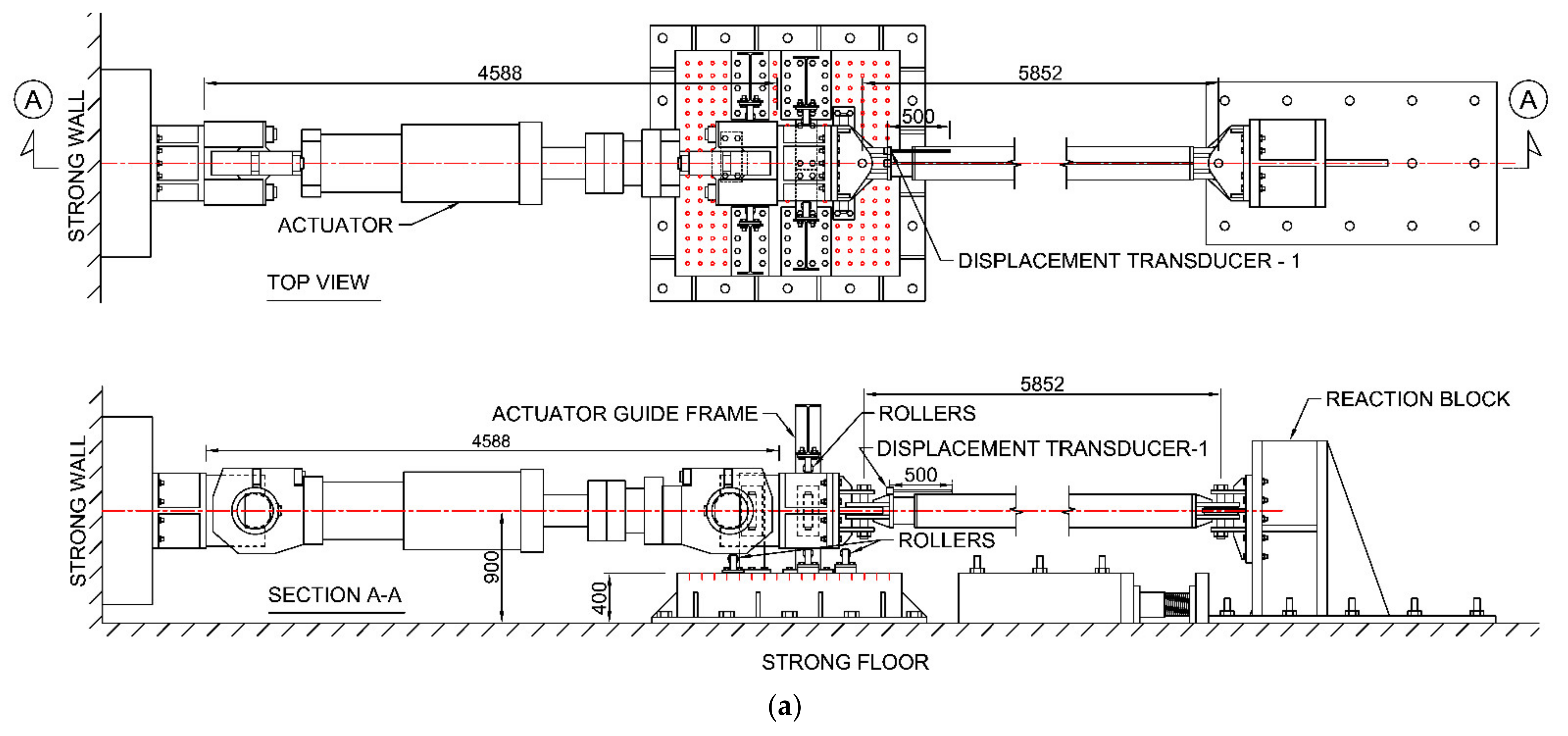
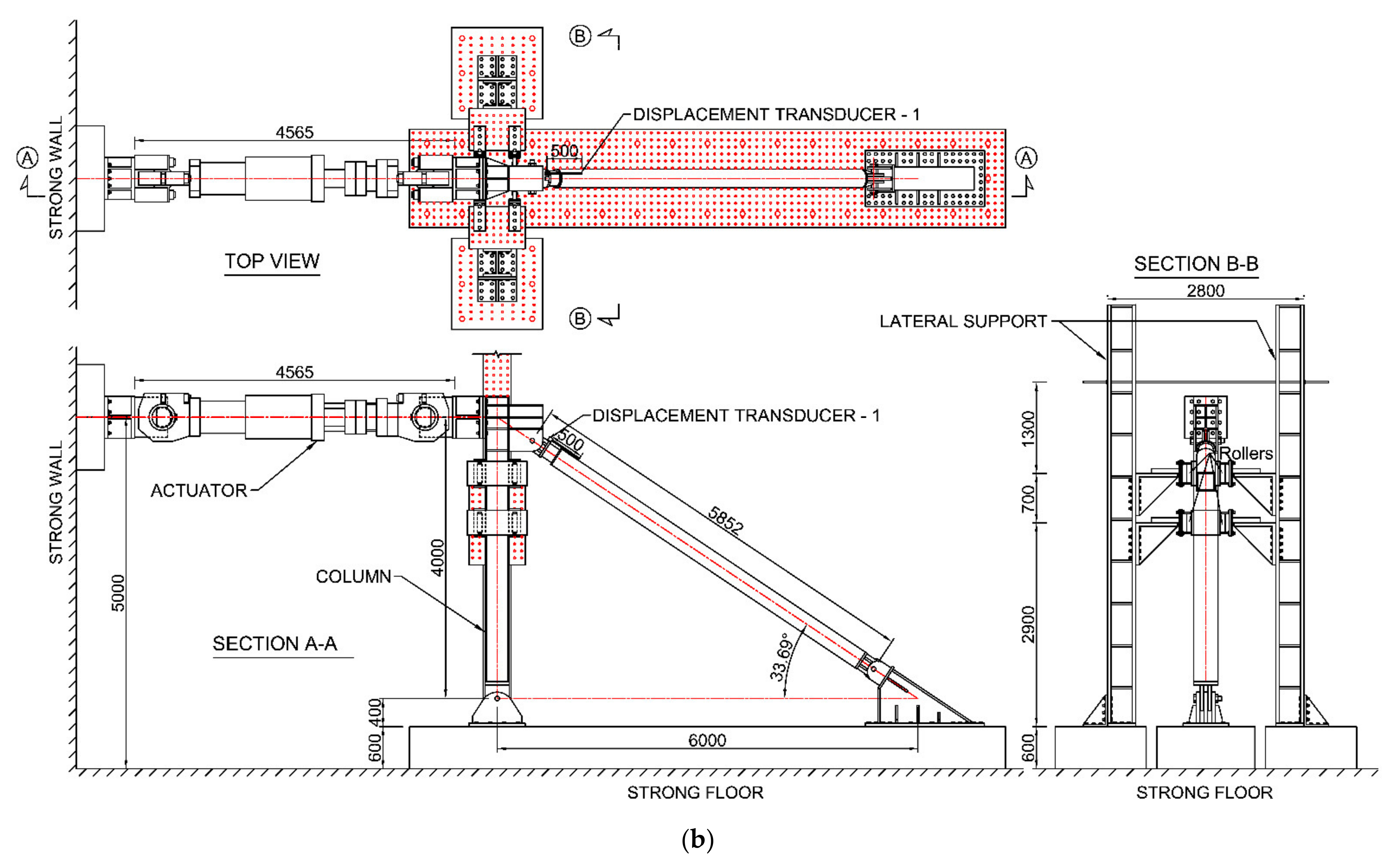
2.2. Test Setup
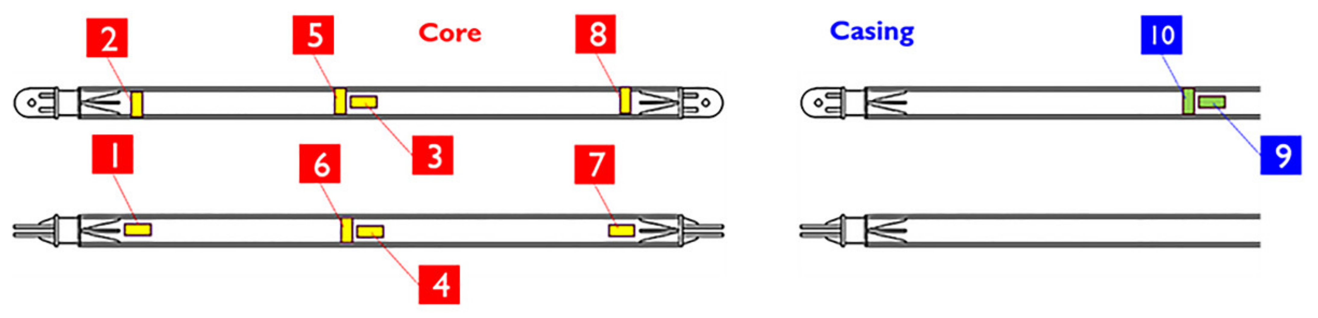
2.3. Instrumentation
2.4. Loading Protocol
3. Test Results
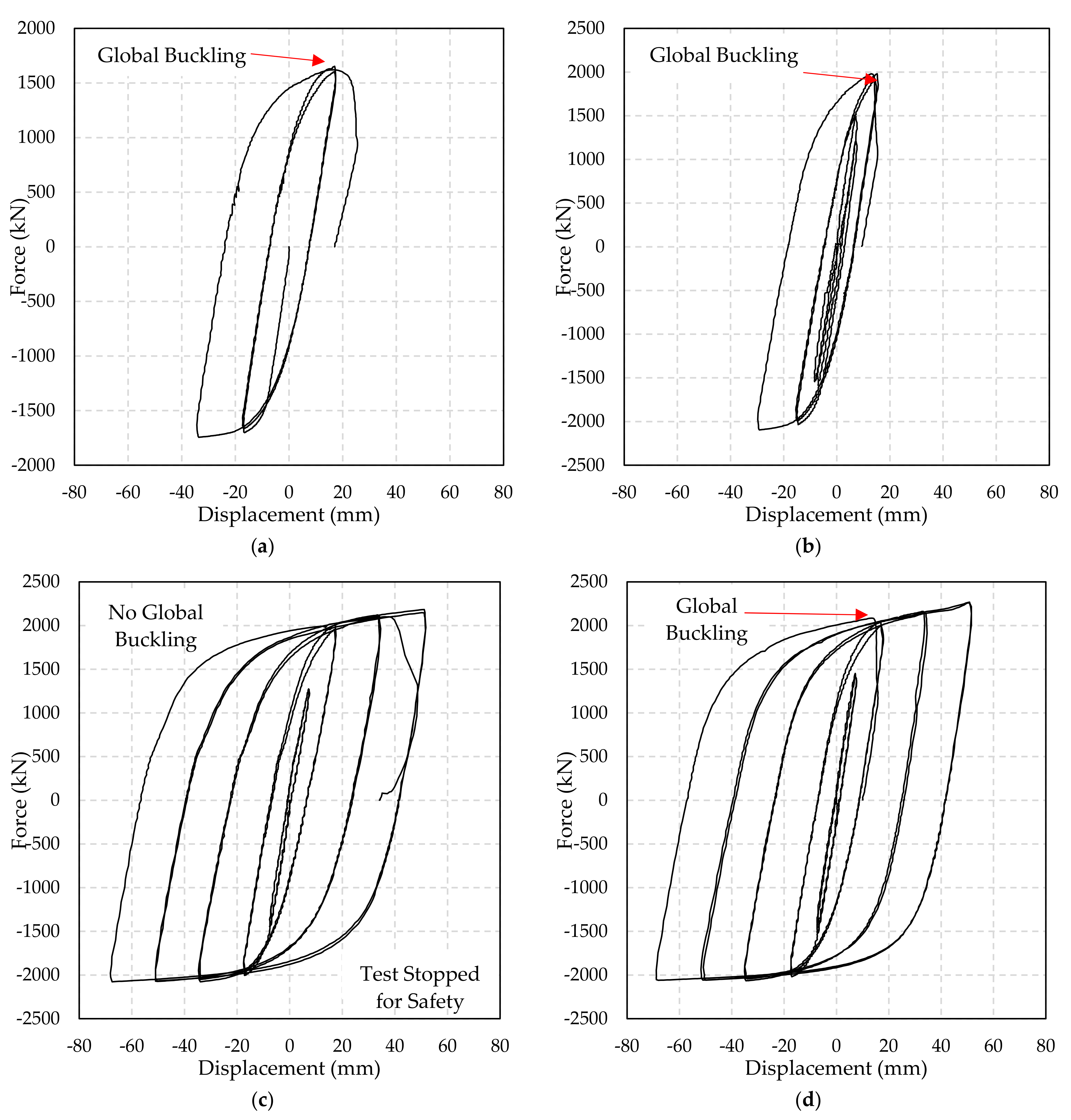
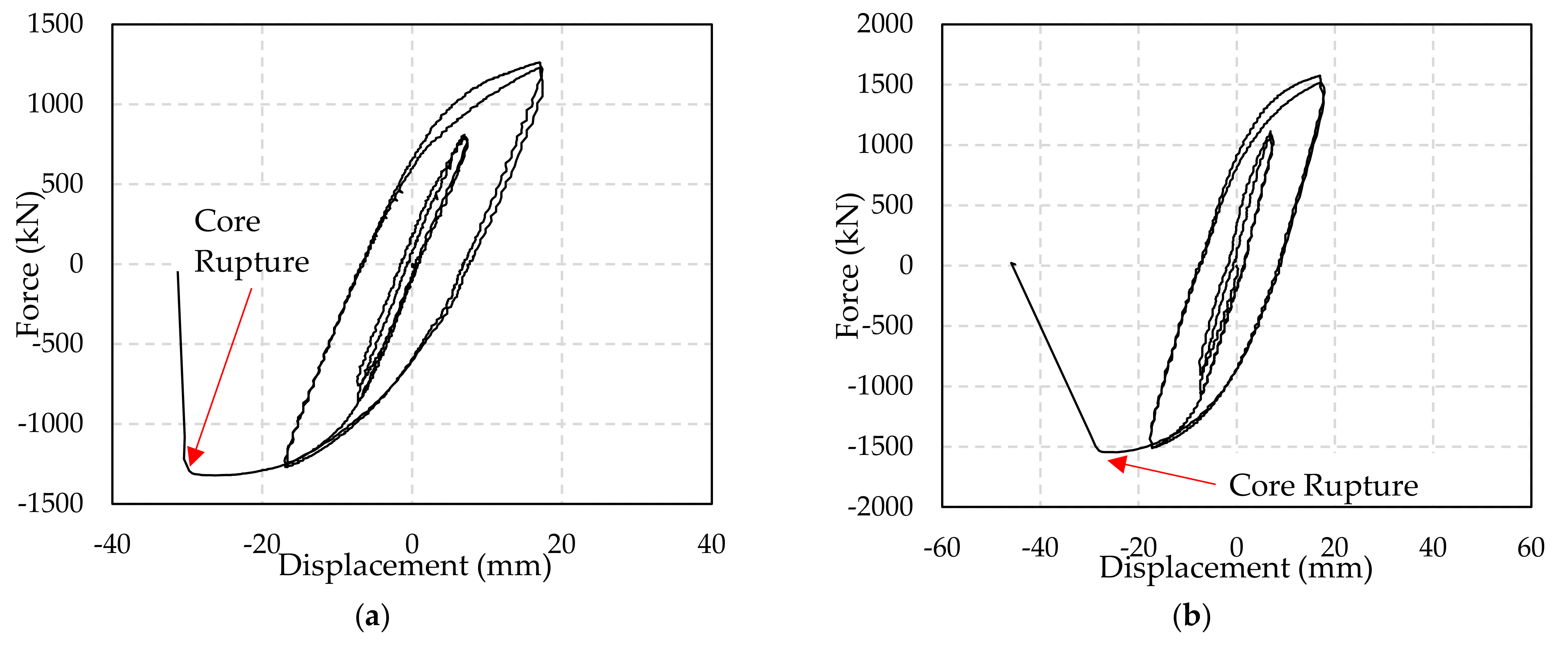
3.1. Circular Specimens
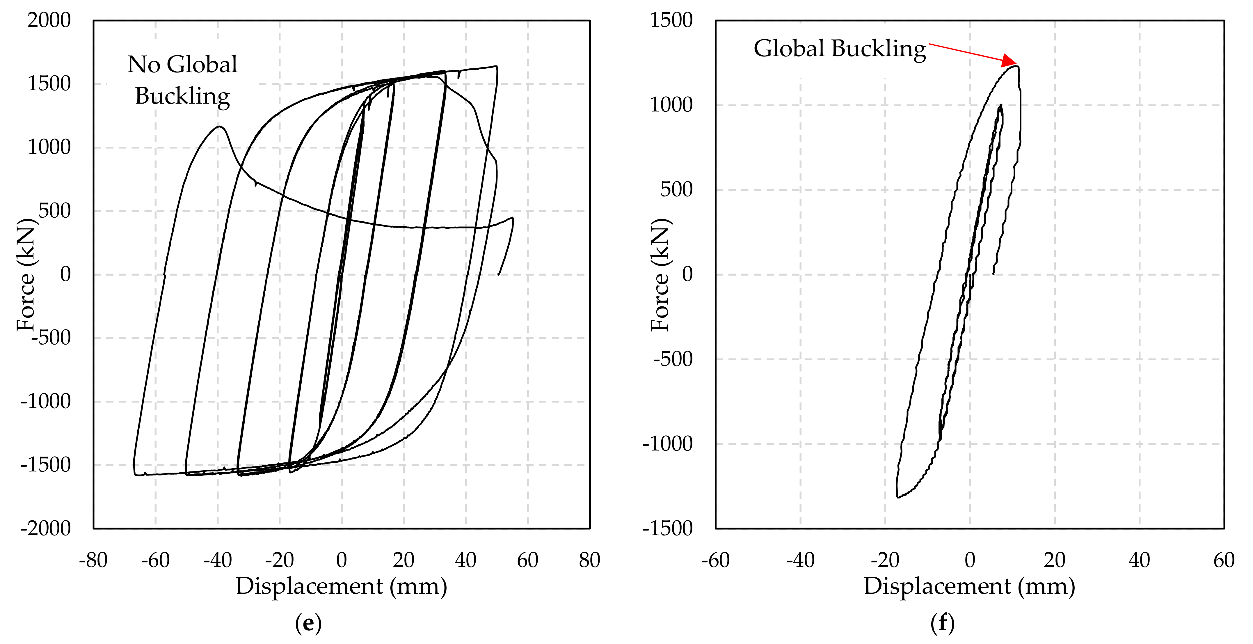
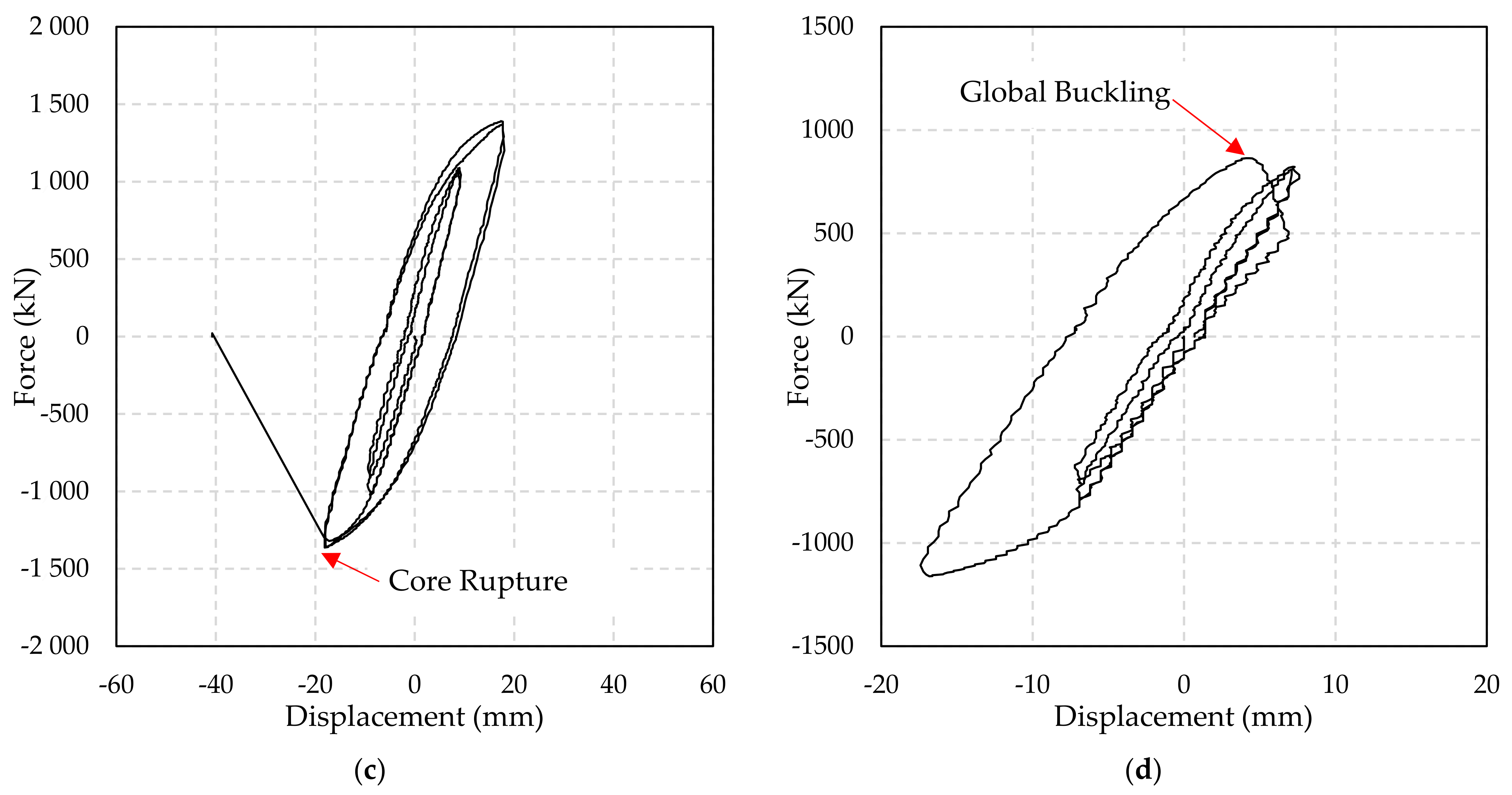
3.2. Square Specimens
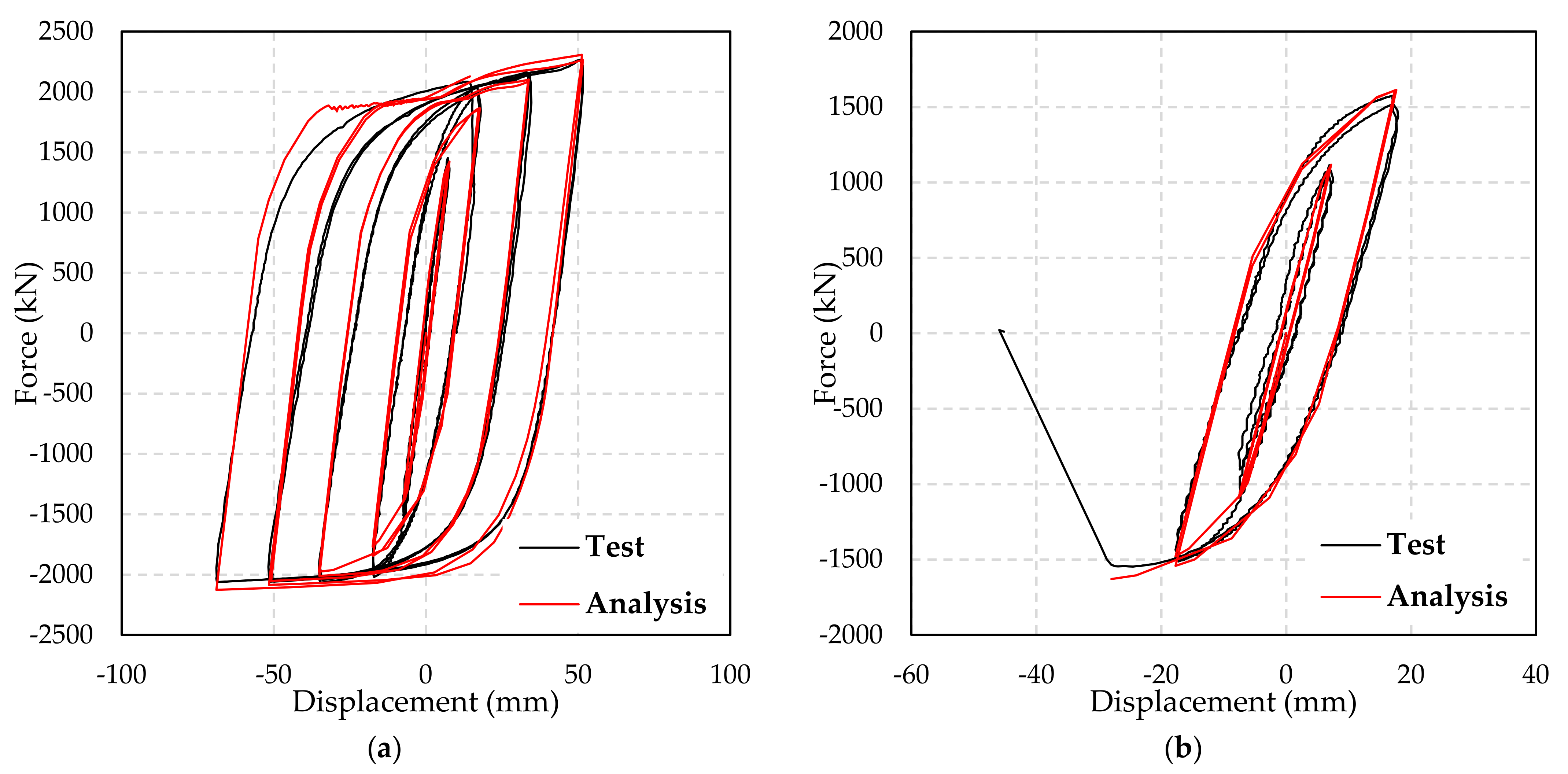
4. Finite Element Analysis
5. Conclusions
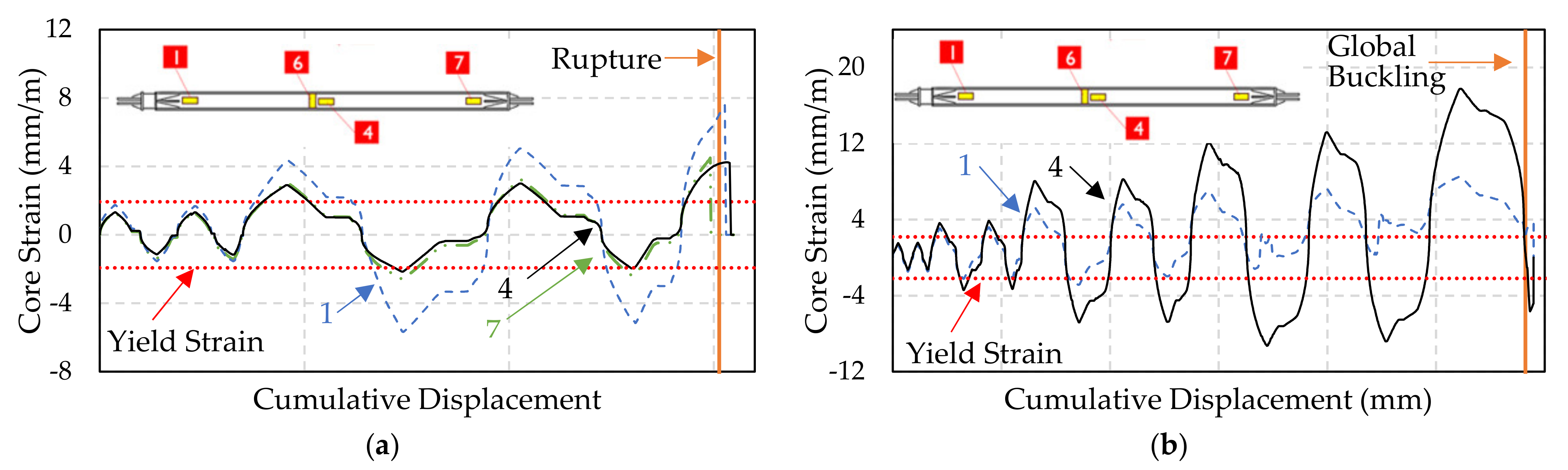
- Despite the leakage of unsolidified filler material, the infilled polymer provided sufficient restraint against strength or stiffness degradation due to local or global core deformation, up to a compressive core strain of 1.1%
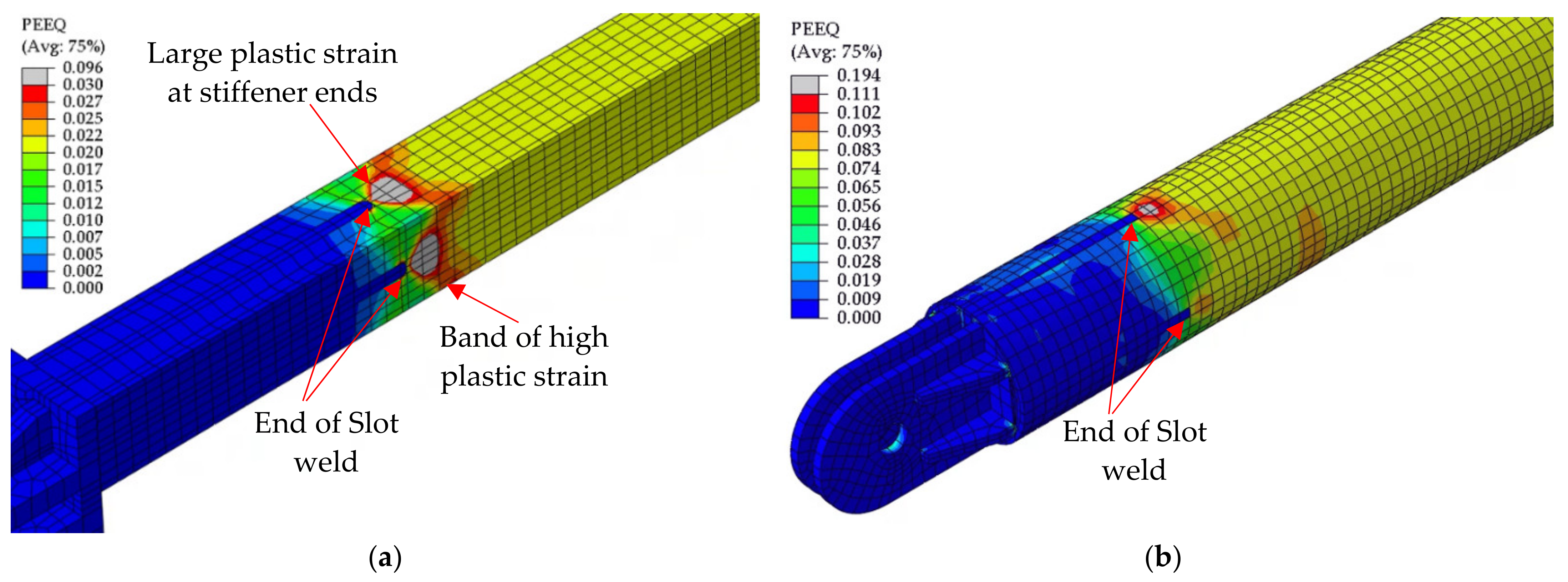
- The slot weld detail adopted for welding stiffeners indicated a stable performance, up to a tensile core strain of 1.46% in circular BRBs. However, the slot weld resulted in a band of high plastic strain region in square BRBs, leading to a premature rupture at tensile core strains ranging from 0.42 to 0.71.
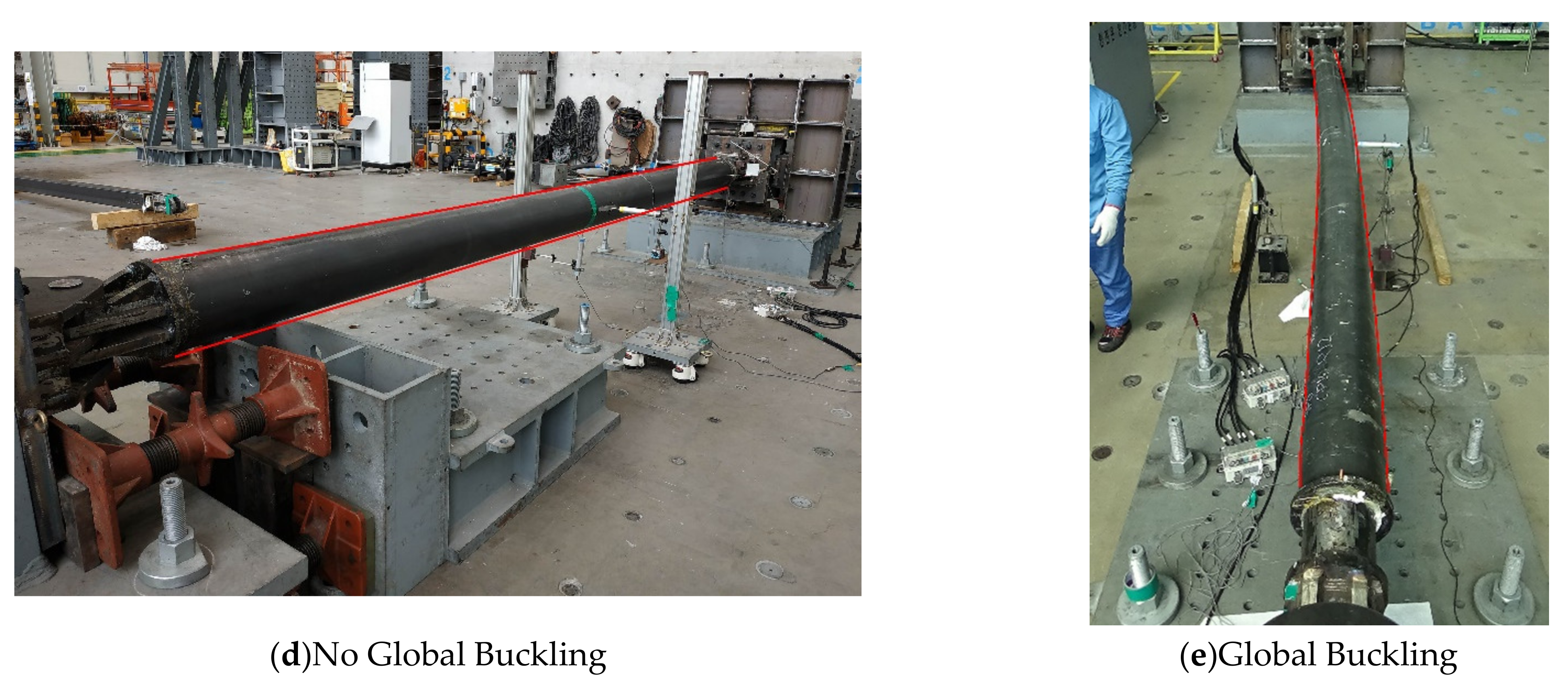
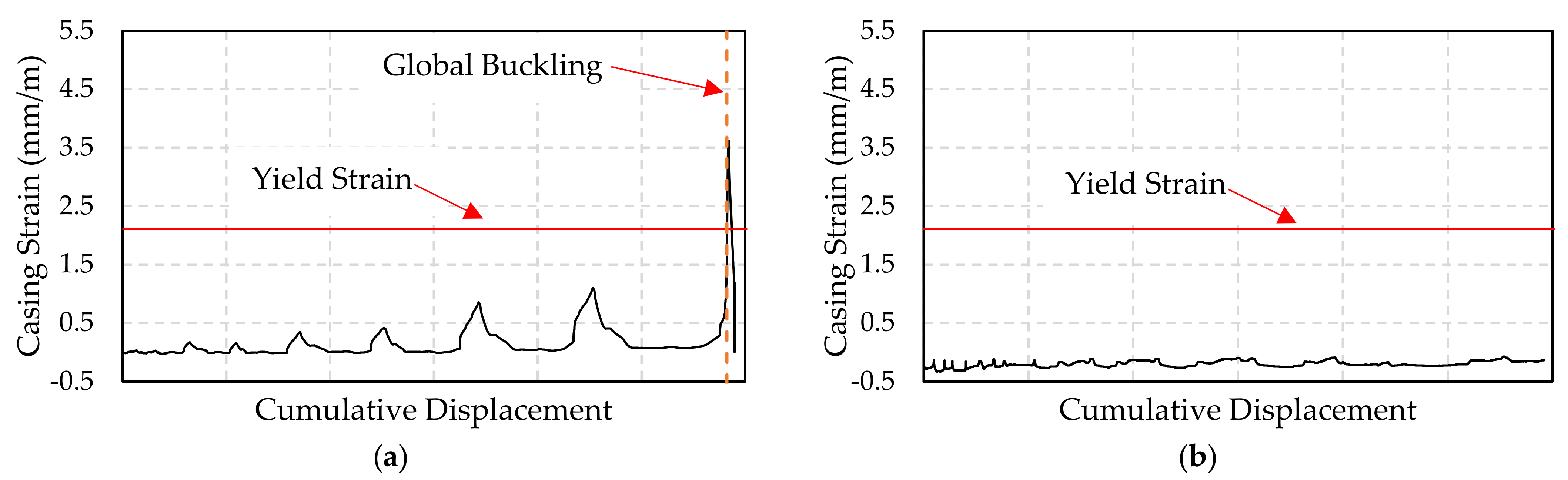
- In circular test specimens with Pcr/Py = 1.06 and a square specimen with Pcr/Py = 0.9, global buckling occurred at a compressive force equal to 77–82% of the critical buckling force when the casing moment reached 92–100% of the casing yield moment. This indicates that global buckling occurred owing to the yielding of the case, and both the stiffness and strength of the casing should be considered when proportioning a BRB.
Author Contributions
Funding
Institutional Review Board Statement
Informed Consent Statement
Data Availability Statement
Conflicts of Interest
References
- Sabelli, R.; Mahin, S.; Chang, C. Seismic demands on steel braced frame buildings with buckling-restrained braces. Eng. Struct. 2003, 25, 655–666. [Google Scholar] [CrossRef]
- Kiggins, S.; Uang, C.-M. Reducing residual drift of buckling-restrained braced frames as a dual system. Eng. Struct. 2006, 28, 1525–1532. [Google Scholar] [CrossRef]
- Naghavi, M.; Rahnavard, R.; Thomas, R.J.; Malekinejad, M. Numerical evaluation of the hysteretic behavior of concentrically braced frames and buckling restrained brace frame systems. J. Build. Eng. 2019, 22, 415–428. [Google Scholar] [CrossRef]
- Mahrenholtz, C.; Lin, P.-C.; Wu, A.-C.; Tsai, K.-C.; Hwang, S.-J.; Lin, R.-Y.; Bhayusukma, M.Y. Retrofit of reinforced concrete frames with buckling-restrained braces. Earthq. Eng. Struct. Dyn. 2015, 44, 59–78. [Google Scholar] [CrossRef]
- Almeida, A.; Ferreira, R.; Proença, J.; Gago, A. Seismic retrofit of RC building structures with Buckling Restrained Braces. Eng. Struct. 2017, 130, 14–22. [Google Scholar] [CrossRef]
- Shin, J.; Kim, J.; Lee, K. Seismic assessment of damaged piloti-type RC building subjected to successive earthquakes. Earthq. Eng. Struct. Dyn. 2014, 43, 1603–1619. [Google Scholar] [CrossRef]
- Clark, P.W.; Aiken, I.D.; Kasai, K.; Kimura, I. Large-Scale Testing of Steel Unbonded Braces for Energy Dissipation. In Proceedings of the American Society of Civil Engineers Structures Congress 2000, Philadelphia, PA, USA, 8–10 May 2000. [Google Scholar] [CrossRef]
- Black, C.J.; Makris, N.; Aiken, I.D. Component Testing, Seismic Evaluation and Characterization of Buckling-Restrained Braces. J. Struct. Eng. 2004, 130, 880–894. [Google Scholar] [CrossRef]
- Palazzo, G.S.; López-Almansa, F.; Cahís, X.; Crisafulli, F. A low-tech dissipative buckling restrained brace. Design, analysis, production and testing. Eng. Struct. 2009, 31, 2152–2161. [Google Scholar] [CrossRef]
- Hoveidae, N.; Tremblay, R.; Rafezy, B.; Davaran, A. Numerical investigation of seismic behavior of short-core all-steel buckling restrained braces. J. Constr. Steel Res. 2015, 114, 89–99. [Google Scholar] [CrossRef]
- Xie, Q. State of the art of buckling-restrained braces in Asia. J. Constr. Steel Res. 2005, 61, 727–748. [Google Scholar] [CrossRef]
- Hoveidae, N.; Rafezy, B. Overall buckling behavior of all-steel buckling restrained braces. J. Constr. Steel Res. 2012, 79, 151–158. [Google Scholar] [CrossRef]
- Zhao, J.; Wu, B.; Ou, J. A novel type of angle steel buckling-restrained brace: Cyclic behavior and failure mechanism. Earthq. Eng. Struct. Dyn. 2011, 40, 1083–1102. [Google Scholar] [CrossRef]
- Alemayehu, R.W.; Kim, Y.; Bae, J.; Ju, Y.K. Cyclic Load Test and Finite Element Analysis of NOVEL Buckling-Restrained Brace. Materials 2020, 13, 5103. [Google Scholar] [CrossRef] [PubMed]
- Kim, D.-H.; Lee, C.-H.; Ju, Y.K.; Kim, S.-D. Subassemblage test of buckling-restrained braces with H-shaped steel core. Struct. Des. Tall Spec. Build. 2014, 24, 243–256. [Google Scholar] [CrossRef]
- Wang, C.-L.; Gao, Y.; Cheng, X.; Zeng, B.; Zhao, S. Experimental investigation on H-section buckling-restrained braces with partially restrained flange. Eng. Struct. 2019, 199, 109584. [Google Scholar] [CrossRef]
- Ryu, J.; Kim, Y.Y.; Park, M.W.; Yoon, S.-W.; Lee, C.-H.; Ju, Y.K. Experimental and numerical investigations of steel-polymer hybrid floor panels subjected to three-point bending. Eng. Struct. 2018, 175, 467–482. [Google Scholar] [CrossRef]
- Wu, H.; Huang, M.; Li, X.; Xia, Y.; Wang, Z.; Fan, G. Temperature-dependent reversed fracture behavior of multilayered TiBw/Ti–Ti(Al) composites. Int. J. Plast. 2021, 141, 102998. [Google Scholar] [CrossRef]
- Zhao, J.; Wu, B.; Ou, J. Flexural Demand on Pin-Connected Buckling-Restrained Braces and Design Recommendations. J. Struct. Eng. 2012, 138, 1398–1415. [Google Scholar] [CrossRef]
- Ju, Y.K.; Kim, M.-H.; Kim, J.; Kim, S.-D. Component tests of buckling-restrained braces with unconstrained length. Eng. Struct. 2009, 31, 507–516. [Google Scholar] [CrossRef]
- Li, C.; Wang, L.; Weng, Y.; Qin, P.; Li, G. Nonlinear Analysis of Steel Structure Bent Frame Column Bearing Transverse Concentrated Force at the Top in Factory Buildings. Metals 2020, 10, 1664. [Google Scholar] [CrossRef]
- Flodr, J.; Krejsa, M.; Mikolasek, D.; Sucharda, O.; Žídek, L. Mathematical Modelling of Thin-Walled Cold-Rolled Cross-Section. Appl. Mech. Mater. 2014, 617, 171–174. [Google Scholar] [CrossRef]
- Alemayehu, R.W.; Jung, S.; Bae, J.; Lee, C.-H.; Ju, Y.K. Tapered reduced deep beam connection for long span steel moment frames. Eng. Struct. 2021, 244, 112731. [Google Scholar] [CrossRef]
- Tsai, K.-C.; Wu, A.-C.; Wei, C.-Y.; Lin, P.-C.; Chuang, M.-C.; Yu, Y.-J. Welded end-slot connection and debonding layers for buckling-restrained braces. Earthq. Eng. Struct. Dyn. 2014, 43, 1785–1807. [Google Scholar] [CrossRef]
- Pan, W.; Tong, J.; Guo, Y.; Wang, C. Optimal design of steel buckling-restrained braces considering stiffness and strength requirements. Eng. Struct. 2020, 211, 110437. [Google Scholar] [CrossRef]
- Chou, C.C.; Chen, S.Y. Subassemblage tests and finite element analyses of sandwiched buckling-restrained braces. Eng. Struct. 2010, 32, 2108–2121. [Google Scholar] [CrossRef]
- Watanabe, A.; Hitomi, Y.; Saeki, E.; Wada, A.; Fujimoto, M. Properties of brace encased in buckling-restraining concrete and steel tube. In Proceedings of the 9th World Conference on Earthquake Engineering, Tokyo, Japan, 2–6 August 1988; Volume 4, pp. 719–724. [Google Scholar]
- American Institute of Steel Construction (AISC). Specification for Structural Steel Buildings; AISC 360-16; American Institute of Steel Construction: Chicago, IL, USA, 2016. [Google Scholar]
- American Institute of Steel Construction (AISC). Seismic Provisions for Structural Steel Buildings; AISC 341–16; American Institute of Steel Construction: Chicago, IL, USA, 2016. [Google Scholar]
- ABAQUS/CAE, version 2017; Software for Technical Computation; Simulia Corp.: Providence, RI, USA, 2017.


| Specimen | Shape | Number of Specimens | Core 1 | Casing 1 | Polymer Thickness (mm) | ||
|---|---|---|---|---|---|---|---|
| Size 1 | Steel Type | Size 1 | Steel Type | ||||
| C216 t8–C267 t6 | Circular | 4 | 216.3 t8 | SRT275 | 267.4 t6 | SJT275 | 17.95 |
| C216 t6–C267 t6 | 1 | 216.3 t6 | SRT275 | 267.4 t6 | SRT275 | 17.95 | |
| C165 t7–C216 t6 | 1 | 165.2 t7 | SRT275 | 216.3 t6 | SRT275 | 17.95 | |
| S125 t9–S200 t9 | Square | 2 | 125 t9 | SRT275 | 200 t9 | SRT275 | 26.90 |
| S125 t7–S200 t9 | 1 | 125 t7 | SRT335 | 200 t9 | SRT275 | 26.90 | |
| S100 t9–S175 t6 | 1 | 100 t9 | SRT275 | 175 t6 | SRT275 | 29.90 | |
| Component | Steel Type | Yield Strength | Ultimate Strength | Elongation | |||
|---|---|---|---|---|---|---|---|
| Average (MPa) | CV 3 (%) | Average (MPa) | CV 3 (%) | Average (%) | CV 3 (%) | ||
| C267 t6 | SJT275 | 422 | 1.25 | 486 | 0.75 | 20.8 | 5.69 |
| C216 t8 | SRT275 | 437 | 0.35 | 476 | 0.59 | 16.8 | 6.33 |
| C216 t6 | SRT275 | 418 | 1.65 | 461 | 1.38 | 20.1 | 6.38 |
| C165 t7 | SRT275 | 441 | 1.06 | 475 | 0.56 | 16.1 | 9.12 |
| S175 t6 | SRT275 | 329 | 0.47 | 421 | 0.46 | 23.0 | 4.58 |
| S125 t9 | SRT275 | 386 | 0.79 | 423 | 0.80 | 18.1 | 6.33 |
| S125 t7 | SRT355 | 525 | 1.98 | 575 | 1.97 | 12.5 | 9.59 |
| S100 t9 | SRT275 | 377 | 1.33 | 426 | 1.66 | 16.0 | 5.24 |
| Stiffener 1 | SM355 | 349 | 1.52 | 524 | 0.84 | 25.9 | 3.85 |
| Pin plates 2 | SM355 | 397 | 1.87 | 534 | 0.23 | 26.9 | 1.53 |
| Specimen | Core | Casing | |||||
|---|---|---|---|---|---|---|---|
| Py (kN) | Pu (kN) | Pcr (kN) | My (kN.m) | Pcy1 | Pcr/Py | Pcy/Py | |
| C216 t8–C267 t6 | 2289 | 2494 | 2427 | 133 | 1991 | 1.06 | 0.87 |
| C216 t6–C267 t6 | 1659 | 1826 | 2427 | 133 | 1991 | 1.46 | 1.20 |
| C165 t7–C216 t6 | 1534 | 1652 | 1264 | 85 | 1072 | 0.82 | 0.70 |
| S125 t9–S200 t9 | 1611 | 1765 | 2415 | 162 | 2048 | 1.5 | 1.27 |
| S125 t7–S200 t9 | 1734 | 1899 | 2415 | 162 | 2048 | 1.39 | 1.18 |
| S100 t9–S175 t6 | 1234 | 1396 | 1114 | 73 | 941 | 0.9 | 0.76 |
| Specimen | Pmax (kN) | δmax (mm) | εmax (%) 3 | 4 | 5 | Failure Mode | |||
|---|---|---|---|---|---|---|---|---|---|
| (+) 1 | (−) 2 | (+) | (−) | (+) | (−) | ||||
| C216 t8–C267 t6-S | 1987 6 | 2097 6 | 25.5 | 34.3 | 0.54 | 0.73 | 0.82 | 1.0 | Global buckling |
| C216 t8–C267 t6-B1 | 1980 | 2096 | 15.6 | 29.7 | 0.33 | 0.63 | 0.82 | 0.99 | Global buckling |
| C216 t8–C267 t6-B2 | 2183 | 2078 | 51.8 | 68.2 | 1.10 | 1.45 | 0.90 | 1.10 | Test stopped for safety |
| C216 t8–C267 t6-B3 | 2267 | 2066 | 51.6 | 68.9 | 1.09 | 1.46 | 0.93 | 1.14 | Global buckling |
| C216 t6–C267 t6-B | 1640 | 1584 | 50.1 | 66.9 | 1.06 | 1.42 | 0.68 | 0.82 | No global buckling |
| C165 t7–C216 t6-B | 1231 | 1317 | 11.9 | 17.3 | 0.25 | 0.37 | 0.97 | 1.15 | Global buckling |
| Specimen | Pmax (kN) | δmax (mm) | εmax (%) 3 | 4 | 5 | Failure Mode | |||
|---|---|---|---|---|---|---|---|---|---|
| (+) 1 | (−) 2 | (+) | (−) | (+) | (−) | ||||
| S125 t9–S200 t9-S | 1517 6 | 1589 6 | 17.4 | 30.4 | 0.40 | 0.71 | 0.63 | 0.74 | Core rupture at the end of the core projection stiffener |
| S125 t9–S200 t9-B | 1574 | 1546 | 17.9 | 27.4 | 0.42 | 0.64 | 0.65 | 0.77 | |
| S125 t7–S200 t9-B | 1390 | 1362 | 18.0 | 18.1 | 0.42 | 0.42 | 0.58 | 0.68 | |
| S100 t9–S175 t6-B | 863 | 1161 | 7.6 | 17.4 | 0.18 | 0.40 | 0.77 | 0.92 | Global buckling |
| Component | Material Model | Interaction with Polymer Infill |
|---|---|---|
| Core | Chaboche combined isotropic and kinematic hardening | Frictionless hard contact with no penetration |
| Polymer infill | Elastic | - |
| Casing | Chaboche combined isotropic and kinematic hardening | Tie constraint |
| Weld | Bilinear | Frictionless hard contact with no penetration |
| Stiffeners and end connectors | Multilinear kinematic with true stress–true strain relation from coupon test | - |
| Model | (MPa) | (MPa) | (MPa) | (MPa) | Q (MPa) | b | |||
|---|---|---|---|---|---|---|---|---|---|
| C216 t8–C267 t6-B3 | 190 | 64,515 | 680 | 123,830 | 9985 | 940 | 1 | 33.75 | 7.15 |
| S125 t9–S200 t9-B | 230 | 109,347 | 869 | 117,933 | 9985 | 4850 | 1 | 33.75 | 7.15 |
Publisher’s Note: MDPI stays neutral with regard to jurisdictional claims in published maps and institutional affiliations. |
© 2021 by the authors. Licensee MDPI, Basel, Switzerland. This article is an open access article distributed under the terms and conditions of the Creative Commons Attribution (CC BY) license (https://creativecommons.org/licenses/by/4.0/).
Share and Cite
Alemayehu, R.W.; Kim, Y.; Park, M.J.; Park, M.; K. Ju, Y. Experimental and Finite Element Study of Polymer Infilled Tube-in-Tube Buckling Restrained Brace. Metals 2021, 11, 1358. https://doi.org/10.3390/met11091358
Alemayehu RW, Kim Y, Park MJ, Park M, K. Ju Y. Experimental and Finite Element Study of Polymer Infilled Tube-in-Tube Buckling Restrained Brace. Metals. 2021; 11(9):1358. https://doi.org/10.3390/met11091358
Chicago/Turabian StyleAlemayehu, Robel Wondimu, Youngsik Kim, Min Jae Park, Manwoo Park, and Young K. Ju. 2021. "Experimental and Finite Element Study of Polymer Infilled Tube-in-Tube Buckling Restrained Brace" Metals 11, no. 9: 1358. https://doi.org/10.3390/met11091358
APA StyleAlemayehu, R. W., Kim, Y., Park, M. J., Park, M., & K. Ju, Y. (2021). Experimental and Finite Element Study of Polymer Infilled Tube-in-Tube Buckling Restrained Brace. Metals, 11(9), 1358. https://doi.org/10.3390/met11091358