Article

Interfacial Reactions between AlSi10 Foam Core and AISI 316L Steel Sheets Manufactured by In-Situ Bonding Process

by
Girolamo Costanza
* and
Maria Elisa Tata
Departiment of Industrial Engineering, University of Rome Tor Vergata, Via del Politecnico 1, 00133 Rome, Italy
*
Author to whom correspondence should be addressed.
Metals 2021, 11(9), 1374; https://doi.org/10.3390/met11091374
Submission received: 7 July 2021 / Revised: 11 August 2021 / Accepted: 30 August 2021 / Published: 31 August 2021
(This article belongs to the Special Issue Advanced Metallic Foams)

Abstract

:
Aluminum foam sandwiches (AFS) with AlSi10 foam cores and AISI 316L steel skins are manufactured by an in-situ bonding process. The precursor of the core foam was made with the powder compacted method. The precursor and skins, coupled together, were then heated up to the melting point of the Al alloy. The gas released by the blowing agent formed hydrogen bubbles in the melt. producing the foam. Such a porous structure was kept frozen at room temperature via cooling in cold water. To optimize the process conditions, some foaming experiments have been conducted with different holding times and temperatures. Such manufactured AFS were cut, chemically etched and studied with an optical microscope associated with image analysis software to get information about pores morphology in terms of circularity and equivalent diameter. The interface AlSi10-AISI316L has been characterized by SEM and EDX to investigate the bonding conditions between cores and skins. Finally, the AFS have been polished and etched to analyze the microstructure. Quasi-static compressive tests have been performed on the AFS. Obtained results showed that the interface formed during the foaming can be characterized by the inter-diffusion of alloying elements, as confirmed by the good quality of metallurgical joints.

1. Introduction

Foams and porous materials with cellular structure [1] show interesting physical and mechanical properties such as low specific weight [2] and, on the other hand, high energy absorption [3], stiffness [4], gas permeability [5] and thermal conductivity [6]. At the same time, sandwich structures integrate the strength of the skin with the stiffness of the core with a significantly reduced weight than their counterparts [7] in an economical way regarding series production [8]. When compressed, the aluminum foam core collapses with large deformations and nearly constant compressive stress. Thanks to their low density and cellular structure, AFS panels show a high strength to weight ratio in combination with unique thermal and acoustic properties. In this work, aluminum foams are used to manufacture Al-foam based sandwich panels and other mechanical parts with complex shapes, which are of great interest for many industrial applications [9,10,11], especially in the transport field. AFS panels consist of a foam core of an Al alloy and two skins of metal (Al, Cu, steel or others) [12]. The structure guarantees high bending stiffness, the capability for energy absorption and high vibration damping associated with reduced weight. Such properties allow them to be employed with low energy consumption and better environmental sustainability in cars, buses, coaches and trains. Sandwich structures manufacturing is usually obtained by ex-situ bonding [13]. In this process, adhesives are employed in order to join together the external skins and the foam in an extremely easy way. On the other hand, high production cost, problems of recycling and poor temperature resistance are the main drawbacks. To overcome such problems, an alternative processing in-situ method has been developed in which the joint occurs as a direct consequence of the foaming process [14]. In this case, the expansion of the foam occurs between two metal sheets kept at a constant distance corresponding to the final one. Dealing with in-situ bonding, an alternative is represented by the preliminary joining of the precursor to the skin. Such a composite is successively formed and, finally, the foaming of the precursor occurs in the oven. In this work, AlSi10 foams and AISI 316L steel sheets have been employed for the manufacturing of Al-alloy aluminum foam sandwiches (AFS) panels. After foaming, the interface Al foam-steel has been characterized by means of SEM observations with EDS and mechanical properties in compressive tests have been determined under different processing parameters.

2. Materials and Methods

The foam core of the AFS panel has been manufactured starting from a precursor of AlSi10 containing 0.8% of foaming agent (TiH2) and 4% of stabilizing agent (SiC). After mixing, the powders have been compacted to obtain a precursor which is successively foamed in the oven [15]. In comparison with pure Al foam, it has been necessary to increase the content of both additives to the Al alloy powders. Furthermore, due to the higher mechanical strength of Al–Si alloys, in comparison with pure Al, it has been necessary to increase the compaction pressure from 12 to 15 t, corresponding to a compaction pressure of about 600 MPa. The process is schematically illustrated in Figure 1. AFS panels have been prepared with two sheets of AlSi 316 L (4 mm thickness) and a precursor of AlSi10.
To guarantee good adhesion of the skins to the core, the AFS steel surfaces were previously mechanically polished (abrasive paper 180–1200 grit) and successively chemically polished (alcohol and acetone) in order to remove the oxide layer. After that a deoxidizing agent was sprayed to hinder the oxidation during the temperature exposure. After the treatment, the assembly (two AISI 316 panels and the AlSi10 precursor) was heated in a horizontal oven at different temperatures (660, 680 and 700 °C) and times (160–350 s). The experiments were carried out to manufacture the samples (cross section 20 × 40 mm), optimizing the process conditions (time and temperature) of the foaming process. During the foaming process in the oven, the external foam walls formed a metallurgical bonding with the steel surface, which was the object of the present study.
The steel-precursor joints of the composite and those of steel-foam sandwich were previously investigated via SEM imaging and EDS microanalysis. EDS analyses have been carried out on the cross-sections realized by cutting the panels with a diamond disk and mechanical polishing of the surface. The metallographic preparation was carried out with grinding, polishing and chemical etching with an aqueous solution of hydrofluoric acid (10%) for 15 s. Sample sections, after etching, were observed by optical microscope and scanning electron microscope. AFS cross sections have been analyzed in terms of circularity and equivalent diameter of the pores, as shown in Figure 2, as a function of the process parameters (time, foaming temperature) with the following relationship:
D e q = 4   A r e a π
C = 4   π   · A r e a P 2
where P is the perimeter calculated with the Crofton formula:
P = π   ( P r 0 ° + P r 45 ° + P r 90 ° + P r 135 ° ) 4
with Pr is the projection of the porosity projection in the direction 0°, 45°, 90° and 135°.
After the analyses, the samples have been subjected to uniaxial compressive test at constant crosshead speed (2 mm/min). The energy absorbed by the AFS during deformation was calculated by numerical integration of the deformation curve up to 50% strain.

3. Results

The structure of the foams and the AFS panels are shown in Figure 2. Macro observation reveals a good quality of the joints at the interface: no cracks and other macro defects were observed. As the mechanical properties of the AFS strongly depend on the extension of the chemical interdiffusion, EDS maps of the main alloying elements in the skin (Fe) and in the foam (Al) have been acquired (Figure 3). These maps show an inter-diffusion process of both chemical elements, with a thickness ranging from 30 to 80 μm occurred during the foaming process.
After foaming, the section of the AFS was polished and the morphology of the porosity was analyzed (Figure 4). A good repeatability of the foaming process was made evident with a standard deviation about 7% for the equivalent diameter of the porosity and about 3% for the circularity. In Table 1, results of morphological study in relation to different foaming temperatures, foaming times, circularity, average equivalent diameter, relative density specific absorbed energy and plateau stress (average value between minimum and maximum in the plateau range) in compressive tests have been reported.
As evidenced from the results in Table 1, higher foaming temperatures and longer foaming times allow the foam to reach lower relative density and, at the same time, higher average diameters of the pores. On the other hand, the changes in terms of pores morphology affect the mechanical properties, with a moderate decrease of the plateau stress in particular. A similar trend is also apparent for the specific absorbed energy. The stress-strain curves for AFS panels (700 °C foaming temperature, 300 s and 240 s foaming time) are reported in Figure 5. The absorbed energy was calculated by numerical integration of the compression curve up to a strain of 50%.
The microstructure of the AlSi10 foams has been analyzed by optical microscopy (OM) and SEM observations. In Figure 6, examples of microstructure are shown. The fine eutectic structure of the Al alloy can be evidenced in the optical microscopy observations surrounded by SiC particles. On the other hand, the edgy shape of the SiC particles can be better highlighted in SEM observation at higher magnification (2300 X), coincident with the particle size (400 mesh, max 37 μm–Sigma Aldrich) of the base powders. This circumstance can be evidenced in Figure 6 left (OM) and right (SEM).

4. Discussion

As evidenced in Figure 6, metallography shows a homogeneous distribution of the SiC particles in the AlSi10 alloy in good agreement with the starting powders size, mixing and foaming processes. At the same time, a fine eutectic structure of the alloy can be ascribed to the imposed fast cooling rate (water quenched at the end of the foam expansion). As a consequence of that, a good repeatability of the manufactured foam has been identified in terms of pores morphology and consequently mechanical properties.
From the analysis of the mechanical tests, it is possible to observe that:
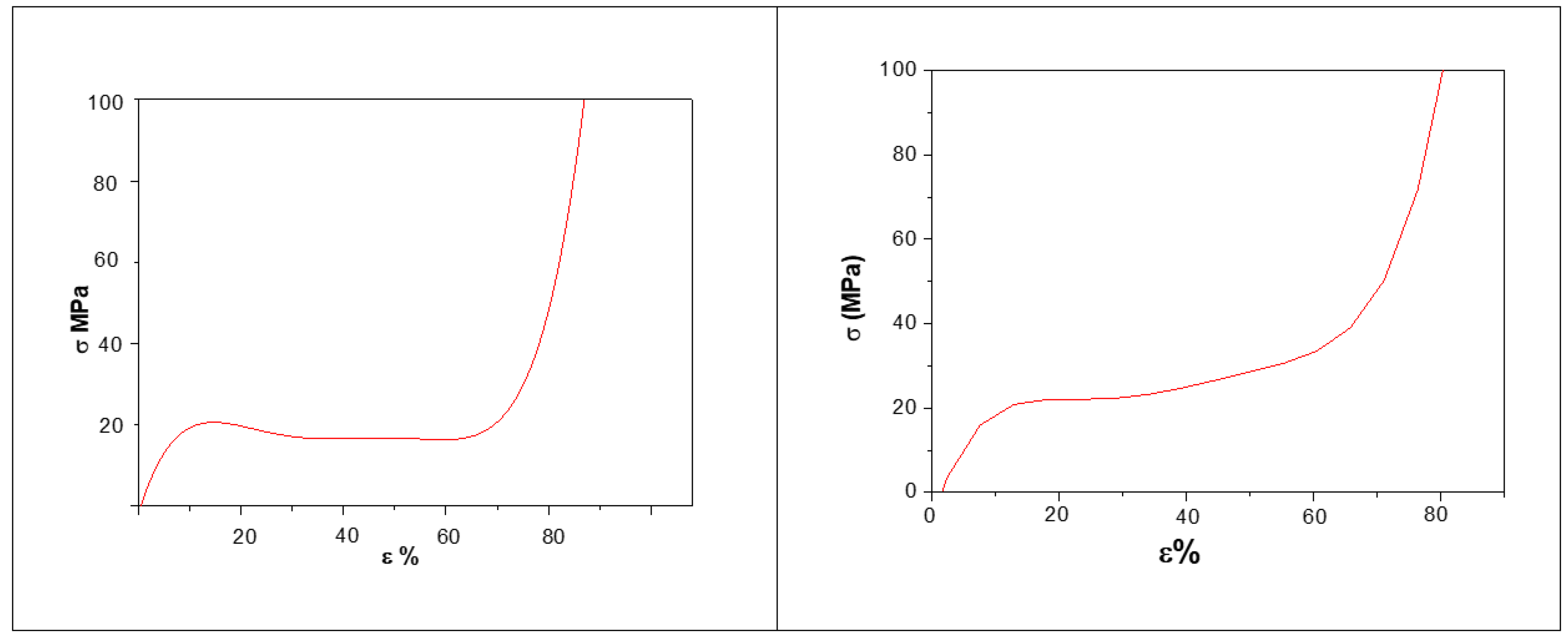
  • an increasing trend of the average plateau stress and of the specific absorbed energy (up to 50% strain) with density increase and this is in good agreement with literature data [16];
  • a more homogeneous porosity at increasing foaming temperatures in the range 660–700 °C has been found in terms of circularity and an increase of the average diameter due to the coalescence phenomenon;
  • as a consequence of that, mechanical properties are significantly modified by the density (and consequently by the average diameters of the pores) rather than circularity change;
  • The foaming time affect positively the circularity and causes an increase of the equivalent diameter up to 300 sec, then the trend is reversed.
  • After that the coalescence phenomenon takes over, the equivalent diameter suddenly increases and, finally, the pore’s circularity is lowered.

5. Conclusions

AlSi10 foams have been joined by in-situ bonding process to AISI 316L steel sheets for the manufacturing of AFS panels, materials of great interest for many industrial applications, particularly in the transport field. The steel-foam joints have been investigated via SEM and EDS microanalysis. The results evidenced that an interface with a thickness of about 100 μm is formed during the foaming process with good interdiffusion of different alloying elements. The good quality of mechanical joints is also shown by the compressive tests in which processing parameters (foaming temperatures and times) have been correlated with the different features of the porosity, average plateau stress and specific energy absorption.

Author Contributions

Conceptualization, G.C. and M.E.T.; methodology, G.C. and M.E.T.; software, G.C. and M.E.T.; validation, G.C. and M.E.T.; formal analysis, G.C. and M.E.T.; investigation G.C. and M.E.T.; conceptualization, G.C. and M.E.T.; methodology G.C. and M.E.T.; data curation, G.C. and M.E.T.; writing original draft preparation, G.C. and M.E.T.; writing review and editing, G.C. and M.E.T.; supervision, G.C. and M.E.T. Both authors have read and agreed to the published version of the manuscript.

Funding

This research received no external funding.

Institutional Review Board Statement

Not applicable.

Informed Consent Statement

Not applicable.

Data Availability Statement

Not applicable.

Conflicts of Interest

The authors declare no conflict of interest.

References

  1. Costanza, G.; Gusmano, G.; Montanari, R.; Tata, M.E. Manufacturing Routes and Applications of Metal Foams. Metall. Ital. 2003, 95, 31–35. [Google Scholar]
  2. Banhart, J. Manufacturing, Characterization and Application of Cellular Metals and Metal Foams. Prog. Mater. Sci. 2001, 46, 559–632. [Google Scholar] [CrossRef]
  3. Costanza, G.; Tata, M.E. Mechanical Behavior of PCMT and SDP Al Foams: A Comparison. Procedia Struct. Integr. 2020, 25, 55–62. [Google Scholar] [CrossRef]
  4. Rizov, V.; Shipsha, A.; Zenkert, D. Indentation Study of Foam Core Sandwich Composite Panels. Compos. Struct. 2005, 69, 95–102. [Google Scholar] [CrossRef]
  5. Khayargoli, P.; Loya, V.; Lefebvre, L.P.; Medraj, M. The Impact of Microstructure on the Permeability of Metal Foams. CSME Forum 2004, 2004, 220–228. [Google Scholar]
  6. Sadeghi, E.; Hsieh, S.; Bahrami, M. Thermal Conductivity and Contact Resistance of Metal Foams. J. Phys. D Appl. Phys. 2011, 44, 125406. [Google Scholar] [CrossRef]
  7. Seeligher, H.W. Manufacture of Aluminum Foam Sandwich (AFS) Components. Adv. Eng. Mater. 2002, 4, 753–758. [Google Scholar] [CrossRef]
  8. Seeligher, H.W. Aluminum Foam Sandwich (AFS) Ready for Market Introduction. Adv. Eng. Mater. 2004, 6, 448–451. [Google Scholar] [CrossRef]
  9. Irven, G.; Duncan, A.; Whitehouse, A.; Carolan, D.; Fergusson, A.; Dear, J.P. Impact Response of Composite Sandwich Structures with Toughened Matrices. Mater. Des. 2021, 203, 109629. [Google Scholar] [CrossRef]
  10. Zhang, X.; Chen, Q.; Gao, J.; Wang, M.; Zhang, Y.; Cai, Z. Numerical Study on the Plastic Forming of Doubly Curved Surfaces of Aluminum Foam Sandwich Panel Using 3d Voronoi Model. Metals 2021, 11, 675. [Google Scholar] [CrossRef]
  11. Zhao, Y.; Yang, Z.; Yu, T.; Xin, D. Mechanical Properties and Energy Absorption Capabilities of Aluminium Foam Sandwich Structure Subjected to Low-velocity Impact. Constr. Build. Mater. 2021, 273, 121996. [Google Scholar] [CrossRef]
  12. Banhart., J.; Seeliger, H.W. Aluminium Foam Sandwich Panels: Manufacture, Metallurgy and Applications. Adv. Eng. Mater. 2008, 10, 793–802. [Google Scholar] [CrossRef]
  13. Weiss, M.; Abeyrathna, B.; Pereira, M. Roll Formability of Aluminium Foam Sandwich Panels. Int. J. Adv. Manuf. Technol. 2018, 97, 953–965. [Google Scholar] [CrossRef]
  14. Sun, X.; Huang, P.; Zhang, X.; Han, N.; Lei, J.; Yao, Y.; Zu, G. Densification Mechanism for the Precursor of AFS under Different Rolling Temperatures. Materials 2019, 12, 3933. [Google Scholar] [CrossRef] [PubMed] [Green Version]
  15. Costanza, G.; Tata, M.E. Metal Foams: Recent Experimental Results and Further Developments. Metall. Ital. 2011, 103, 3–7. [Google Scholar]
  16. Grilek, K.; Maric, G.; Jakovljevic, S. A Study on Energy Absorption of Aluminium Foam. BHM 2010, 155, 231–234. [Google Scholar] [CrossRef]
Figure 1. Sketch of the powder compacted method for Al foams manufacturing.
Metals 11 01374 g001
Figure 2. (left) Sectional view sketch of a sandwich panel (black AISI 316 sheets and white Al alloy foams) and (right) cross-section view of a sandwich panel.
Metals 11 01374 g002
Figure 3. Elemental map of Fe (left) and Al (right), acquired by EDS microanalysis across the skin-core interface: core of AlSi10 foam (on the bottom) and skin of AISI 316 steel (on the top). Manufacturing temperature 660 °C and time 160 s.
Metals 11 01374 g003
Figure 4. Image analysis examples on AFS sections 660 °C, 16 s (a,b), and core sections (c,d).
Metals 11 01374 g004
Figure 5. Stress–strain diagram for AFS panels foamed at 700 °C, for 300 and 240 s.
Metals 11 01374 g005
Figure 6. Metallography with OM (left) and SEM (right) on core-samples AlSi10 foam illustrating the microstructure of the alloy and the polygonal SiC particles, respectively.
Metals 11 01374 g006
Table 1. Foaming temperature and time, circularity, average equivalent diameter, relative density, specific absorbed energy and plateau stress of manufactured AFS (average values).
Foaming Temperature
(°C)
Foaming Time
(s)
CircularityAverage Equivalent Diameter
(mm)
Relative Density
(ρ/ρ0)
Specific Absorbed Energy
(J/g)
Plateasu Stress σpl
(MPa)
6601600.471.70.327.520
6601800.501.90.287.219
6602200.512.20.277.018
6602400.542.50.256.818
6602800.602.80.236.717
6603000.653.10.226.517
6603500.554.60.236.817
6801600.601.90.317.619
6801800.681.950.297.518
6802200.712.10.287.318
6802400.752.30.267.117
6802800.772.50.257.017
6803000.812.80.246.816
6803500.673.80.257.817
7001600.681.80.317.720
7001800.701.90.307.619
7002200.722.30.287.518
7002400.752.50.267.418
7002800.782.80.247.317
7003000.803.20.227.116
7003500.704.00.216.516
Publisher’s Note: MDPI stays neutral with regard to jurisdictional claims in published maps and institutional affiliations.

