Abstract
Axial cracking and circumferential wrinkling are found at the end of seamless steel tubes during multi-pass large deformations pushing diameter-reducing (PDR), which seriously affects product quality. However, the cracking and wrinkling mechanism of PDR has not been elucidated yet. In this paper, the Equation of circumferential residual stress at the end was deduced from the warping deformation and shear stress. It is revealed that the circumferential residual stress in the end warping area from the inner to outer surface is tensile, and the generation mechanism of circumferential wrinkling on the inner wall at the end was revealed through the deformation analysis of PDR. The geometric model of the tube with periodic alternating variation of wall thickness was established to reveal the generation and development of circumferential wrinkling. In addition, the four-pass PDR experiments and simulations were developed to reveal the influence of reducing pass and wall thickness deviation on the end warpage, unevenness and circumferential residual tensile stress. The pushing-pulling diameter-reducing (PPDR) method was proposed to control the wrinkling and cracking. The simulation and experimental results showed that the end warpage, unevenness and circumferential residual tensile stress are all greatly decreased, and the risk of axial cracking and circumferential wrinkling is eliminated.
1. Introduction
PDR refers to the cold forming method that consists of reducing the tube diameter by a conical die [1,2]. It has the advantages of high production efficiency, low manufacturing cost and simple die structure and has been widely used in the manufacturing of reducing tubes in automobiles, engineering machinery and aerospace [3,4,5].
There are many studies on diameter-reducing deformation and force. Rumiński et al. [6] presented the influence of different die shapes on the strain field distribution of the reducing tube by simulation and hardness measurements. Lu [7] obtained the approximate calculation method of the reducing ratio and loading rate by using the volume invariant condition and Mises equation. Zhao et al. [8] established the strain velocity field of tube drawing, and the drawing force was solved based on the inner product integral of strain rate vector. Ogbeyemi et al. [9] revealed the stress and pressure fields of the reducing tube by using Bubnov-Galerkin finite element model. Sadok et al. [10] analyzed the strain state of the reducing tube by finite element simulation and carried out the hardness measurement; the results showed that the reducing deformation is uneven, and the maximum effective strain is on the tube’s inner surface.
Due to the uneven reducing deformation, the residual stress exists in the reduced tube [11]. Vollert et al. [12] researched the residual stress of medium carbon tube with hollow and fixed mandrel drawing and revealed that the circumferential residual stress on the inner and outer surface is compressive and tensile, respectively. Gattmah et al. [13] developed the fixed mandrel drawing residual stress of AISI 1010 tube with the different reduction of the area by an X-ray method. The results showed that the circumferential residual stress near the outer and inner surface at the small reduction of the area is compressive and tensile, respectively. Kishimoto et al. [14] elucidated the mechanism causing the excessive thinning of the outer diameter during microscale hollow drawing by considering the size effect and plastic anisotropy.
Different from the tube drawing, the tube is subjected to the pushing force during the PDR, and it is not affected by external force after reducing it, while the end of the reduced tube is warped. Liu et al. [15] studied the residual stress of one-pass PDR tube without wall thickness deviation by the X-ray method and simulation, the results showed that the circumferential residual stress is tensile from the inner to outer surface at the end, and it is compressive and tensile at the inner and outer surface of sizing area, respectively.
The axial buckling and wrinkling may occur in the middle area of the PDR tube due to the excessive reducing force. Liu et al. [16] investigated the influence of temperature on the axial instability of the hot extrusion transmission shaft and provided the optimal forming parameters without axial instability. Teng et al. [17] studied the influence of die cone angle on the wrinkling of reducing thin-walled cylindrical cup, and presented that the larger the cone angle, the easier the wrinkling.
Different from the PDR, the circumferential buckling and wrinkling exist in the middle deformation area of the tube with outer pressure necking in a viscous or solid particle medium. Many studies have researched the circumferential wrinkling of thin- walled alloy tube with outer pressure necking. Zhao et al. [18] analyzed the wrinkling of thin-walled tube with outer pressure necking and researched the influence of forming factors on the anti-wrinkle of outer pressure necking tube. Zhang et al. [19] revealed the effect of the buckling mode and uneven thickness defect on the wrinkling of outer pressure necking tube by finite element simulation.
In the engineering practice of the multi-pass large deformation PDR of a seamless steel tube, it is found that the end of reduced tube is warped, and there is axial cracking and circumferential wrinkling at the end of individual reduced tube, which seriously affects the quality of the products, as shown in Figure 1. However, the cracking and wrinkling mechanism of PDR has not been reported yet.
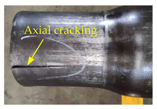
Figure 1.
Axial cracking of reduced tube end.
In this paper, for the seamless steel tube with the multi-pass large deformation PDR, the Equation of circumferential residual tensile stress at the end was deduced, and the generation mechanism of circumferential wrinkling on the inner wall at the end was revealed through theoretical analysis. The influence of wall thickness deviation and reducing pass on circumferential residual stress, end warpage and unevenness were revealed by finite element analysis (FEA) and the experiment (EXP). In order to control the axial cracking and circumferential wrinkling, a new method of PPDR was proposed, which improves the forming quality of the reduced tube and provides a reference for engineering application.
2. Geometric Model of Seamless Steel Tube
2.1. Wall Thickness Measurement
Hot-rolled seamless steel tube is generally adopted in large deformation PDR processes. Due to the run-out and wear of rolling mandrel and the uneven heating of the tube, the unavoidable wall thickness deviation defects exist in the tube [20,21]. The hot-rolled seamless steel tube Q345B selected for the bulging-pressing-formed automobile axle housing [22] with a load of 6.5 tons is taken as the research object. For the initial tube, the length L0 is 1350 mm, the outer diameter d0 is 219 mm and the nominal wall thickness is 7.5 mm. The chemical composition and mechanical properties of the Q345B seamless steel tube is shown in Table 1 and Table 2, respectively. The true stress-strain curve of the initial tube is shown in Figure 2.

Table 1.
Chemical composition of the Q345B seamless steel tube (%).
Table 2.
Mechanical properties of Q345B seamless steel tube.

Figure 2.
Stress-strain curve of the initial tube.
On the tube’s outer surface, the circles are drawn with equal spacing of 145 mm and the axial lines are drawn with an equal circumferential interval angle of 15°. Accordingly, the intersection of the circle and axial lines is the wall thickness measuring point, the sections where the circles are located are designated as cross-section P1 to P10, respectively, as shown in Figure 3.

Figure 3.
Schematic diagram of wall thickness measurement.
The maximum and minimum wall thickness are expressed as tm0 and tn0, respectively; the average wall thickness is expressed as t0, the difference between the tm0 and t0 is defined as the positive deviation Tm, the difference between the tn0 and t0 is defined as the negative deviation Tn and the difference between the tm0 and tn0 is defined as the initial wall thickness deviation T0. Ten tubes are randomly selected, and the wall thickness is measured by MT-160 ultrasonic thickness gauge. The measurement results of the half partial cross-section are shown in Figure 4, and the wall thickness distribution of the other half is symmetrical. The measurement results are as follows:
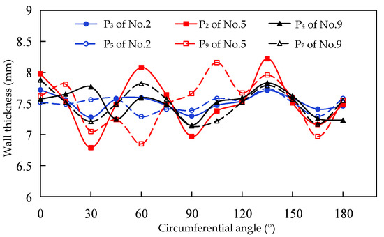
Figure 4.
Circumferential wall thickness distribution.
- (1)
- The wall thickness along the circumferential direction is alternately thin and thick, such as the wall thickness of P3 and P5 cross-section of No.2 tube, P2 and P9 cross-section of No.5 tube, P4 and P7 cross-section of No.9 tube all varies alternately from 0° to 180°.
- (2)
- The absolute value of the maximum positive and negative deviation wall thickness on the same cross-section is close. Such as the maximum positive and negative deviation wall thickness of P3 cross-section of No.2 tube is 0.35 mm and −0.33 mm, respectively, P2 cross-section of No.5 tube is 0.62 mm and −0.65 mm, respectively, P7 cross-section of No.9 tube is 0.40 mm and −0.42 mm, respectively.
2.2. Geometric Model
Based on the measurement results of seamless steel tube wall thickness, the assumptions are made as follows:
- (1)
- The tube’s outer surface shape is a circle, and the inner surface shape is a periodic sinusoidal variation and the wall thickness on the same axis are equal.
- (2)
- The absolute value of the maximum positive deviation Tm and the maximum negative deviation Tn of the same cross-section wall thickness are equal.
Based on the above assumptions, the geometric model of tube with wall thickness deviation is established, as shown in Figure 5. The trough of the inner wall’s sine curve is the minimum wall thickness tn0, and the crest is the maximum wall thickness tm0. The amplitude is T0/2, the period angle is θn, the wave number is n.
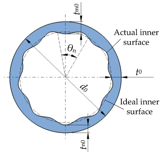
Figure 5.
Geometric model of tube with wall thickness deviation.
2.3. Definition of Unevenness
2.3.1. Unevenness T
The difference between the maximum wall thickness tm and the minimum wall thickness tn of the same cross-section is defined as unevenness T, which is expressed as
2.3.2. Relative Unevenness K
The ratio of unevenness T to the average inner diameter di is defined as relative unevenness K, which is expressed as
The relative unevenness K is used as an evaluation index for whether the circumferential wrinkling produced.
2.3.3. Critical Relative Unevenness Kc
The maximum wall thickness deviation of seamless steel tube allowed by GB/T8162-2018 (China Standard) [23] is Tx. The ratio of Tx to the initial tube inner diameter di0 is defined as the critical relative unevenness Kc, which is expressed as
When the relative unevenness K of reduced tube is greater than the critical relative unevenness Kc, it is evaluated as the circumferential wrinkling.
3. Mechanical Analysis
During the PDR, the upper and lower clamping die is used to fix the middle area of the tube, and the reducing die is reduced from the tube’s end to the inner side. The cavity of the reducing die is divided into the reducing area, the rounded corner area and the exit area, as shown in Figure 6. Based on the deformation characteristics in each area of the reducing die, the PDR deformation process can be divided into reducing stage, bending stage and warping stage. The mechanical model of the PDR tube with a wall thickness deviation is established, the upper and lower sides of the tube are defined as the thick and thin wall side, respectively. For the reducing die, the half-cone angle is α, the inner diameter of the exit area is dm and the rounded corner radius is R. For the initial tube, the diameter is d0, the intermediate layer radius of the thick and thin wall side is Rm0 and Rn0, respectively, and the corresponding wall thickness is tm0 and tn0, respectively.
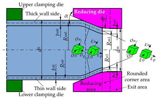
Figure 6.
Reducing stage.
3.1. Reducing Stage
After the tube is deformed in the reducing stage, the intermediate layer radius of the thick and thin wall sides decreases to Rm1 and Rn1, respectively, and the corresponding wall thickness increases to tm1 and tn1, respectively, as shown in Figure 6.
In the reducing stage, the tube wall thickness is increased while the diameter is reduced, and the length is elongated along the axial direction. The circumferential compressive strain is the main deformation, so that the thick wall side metal flows to the adjacent thin wall side, which is beneficial to decrease unevenness. The normal compressive stress is smaller than the circumferential compressive stress. The axial stress of the end is approximately zero, and on the inner side of the end it is compressive.
3.2. Bending Stage
After the tube is deformed in the reducing stage, it flows into the rounded corner area of the reducing die and continues to undergo axial bending deformation, as shown in Figure 7. Furthermore, after the tube is deformed in the bending stage, the intermediate layer radius of the thick and thin wall side is Rm2 and Rn2, respectively, the corresponding wall thickness is tm2 and tn2, respectively, and the tube end diameter d02 is less than the inner diameter dm of the reducing die exit area.

Figure 7.
Bending stage.
3.2.1. Basic Assumptions
- (1)
- The intermediate layer of tube wall coincides with the neutral layer.
- (2)
- The axial compressive stress on the outside of the intermediate layer acts on half of its thickness with equivalent compressive stress. The axial tensile stress on the inside of the intermediate layer acts on half of its thickness with equivalent tensile stress. In addition, the absolute value of equivalent axial stress on the inside and outside is equal.
- (3)
- On the same cross-section, the torque caused by the axial stress on the inside and outside of intermediate layer on circumferential unit angle micro-plane is equal.
3.2.2. Deformation Analysis
The element body including inner and outer surface of the tube is intercepted in the bending deformation area, as shown in Figure 8. The axial length is dl, the circumferential length is dy and the wall thickness is te. On the right surface, the axial equivalent compressive stress on the outside of intermediate layer is σρe1, the axial equivalent tensile stress on the inside of intermediate layer is σρe2 and the value of σρe1 and σρe2 is equal. The torque dM on the right surface is

Figure 8.
Element body of bending deformation area.
In the bending stage, the outside metal of the intermediate layer is shortened along the axial direction and the thickness is increased, while the inside metal of the intermediate layer is elongated, and the thickness is decreased. Based on the basic assumptions and the wall thickness of the thin and thick wall side, it can be known from the Equation (4) that the axial tensile stress on the inside of the intermediate layer of the thin wall side is greater than that of the thick wall side. So, the axial deformation and thinning at the inside of the intermediate layer of the thin wall side is larger than that of the thick wall side, which results in the unevenness is increased on the inner wall of the end.
3.3. Warping Stage
After the tube end is deformed in the bending stage, the axial elongation of the inside metal of the intermediate layer is greater than that of the outside, so that the end warped upward to form end warping area. As shown in Figure 9, there is shear deformation in the end warping area, which results in the shear stress τnρ on the lower surface of unit body pointing from left to right, and the shear stress τρn on the right surface of unit body pointing from top to bottom. After the tube end deformed in the warping stage, the intermediate layer radius of the thick and thin wall side is increased to Rm3 and Rn3, respectively, the corresponding wall thickness is decreased to tm3 and tn3, respectively.
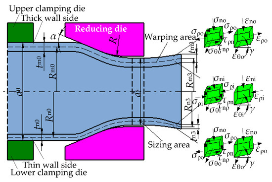
Figure 9.
Warping stage.
3.3.1. Basic Assumptions
- (1)
- Due to the PDR deformation is axisymmetric, the circumferential stress is main stress, the shear stress components related to the circumferential direction are all zero.
- (2)
- Axial residual stress on the cross-section of reduced tube is self-balanced from the inner to outer surface.
3.3.2. Analysis of End Residual Stress
The element body including the inner and outer surface of the tube is intercepted in the end warping area, and the left surface of the element body is the interface between warping area and sizing area, as shown in Figure 10. For the element body, the front side is thin wall side with the wall thickness tn, the rear side is thick wall side with the wall thickness tm, the circumferential angle between the front and rear surface is dθ, the outer circumferential curvature radius of the left and right side is d1/2 and d2/2, respectively, the axial curvature radius and included angle of the upper side is rρ and β, respectively. The right, upper and lower surface are all free surfaces. On the left surface, the shear stress τρn pointing from bottom to top, and there is axial tensile stress σρo and compressive stress σρi on the outer and inner layer, respectively, the axial resultant force is zero. The circumferential stress on the front and rear surface is σθm and σθn, respectively.

Figure 10.
Element body of end warping area.
According to the equilibrium condition of force in the wall thickness direction, it can be obtained as
Since dθ is very small, and sin (dθ/2) = dθ/2 is approximated, the above Equation (5) is simplified as
Based on the geometric analysis, the approximate Equation is
Substituting the Equation (7) into (6) to obtain
According to the equilibrium condition of force in the tangential direction, it can be obtained as
Substituting the Equation (9) into (8) to obtain
According to the Equation (10), the circumferential residual stress σθ in the end warping area is related to end warping deformation parameters and shear stress τρn. Since the direction of the τρn is upward, the σθ is characterized as tensile stress from the inner to outer surface and the σθ is verified as tensile stress by the X-ray measurement and FEA in the literature [15]. Moreover, the σθn of the thin wall side is greater than the σθm of the thick wall side. When the circumferential residual tensile stress of the end is greater than the ultimate tensile strength, axial cracking may occur and the axial cracking is more likely occur on the thin wall side.
3.3.3. Unevenness Analysis
The tube end is warped in the warping stage, which results in the end diameter expansion and wall thickness thinning. Due to the σθn is greater than the σθm, the circumferential deformation and thinning of the thin wall side is larger than that of the thick wall side, which results in the end unevenness is further increased. When the relative unevenness exceeds the critical value, circumferential wrinkling will be generated. However, the inner side of the end is no longer warped, the unevenness is no longer changed as well, and the sizing area is formed. The outer diameter of the sizing area is less than the inner diameter of the exit area of the reducing die.
4. Research Methods
4.1. Research Objects
The hot-rolled seamless steel tube Q345B is selected as the initial tube with the length L0 of 1350 mm, the outer diameter d0 of 219 mm and the nominal wall thickness of 7.5 mm. According to the GB/T8162-2018 [23], the maximum allowable wall thickness deviation is 2.25 mm, so the critical relative unevenness Kc is 1.10%. During diameter-reducing, the middle area of the tube is clamped by clamping die, which is to keep the length of 456 mm without deformation, as shown in Figure 11. Moreover, the radius of upper and lower clamping die is 109.5 mm.
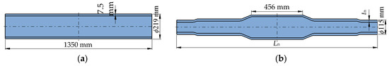
Figure 11.
Process diagram of PDR. (a) Initial tube; (b) reduced tube.
4.2. PDR Experiments
The initial unevenness T0 of 0.4 mm, 0.8 mm and 1.2 mm was selected, respectively. Four-pass PDR was carried out on the THP63-200/300/100 × 2 hydraulic press. The reducing die of each pass is shown in Figure 12, the half-cone angle α is 23°, the rounded corner radius R is 50 mm and the inner diameter of the exit area dm is 190 mm, 162 mm, 138 mm and 115 mm, respectively.
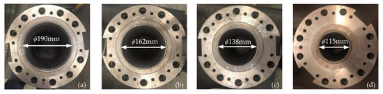
Figure 12.
Reducing dies. (a) First pass; (b) second pass; (c) third pass; (d) fourth pass.
Before diameter-reducing, the outer wall of both ends of the tube and the inner wall of the reducing die are lubricated by lubricating oil, then the tube is placed into the lower clamping die and the center is aligned. During diameter-reducing, the upper clamping die is driven by the upper slider of hydraulic press to move downward to clamp the middle area of the tube, and the left and right reducing die are respectively pushed by the left and right slider of hydraulic press from the tube end to the inner side at the speed of 10 mm/s.
4.3. Stress-Strain Relationship
The tensile specimens with ASTM-E8 standard were obtained by cutting in the initial tube and the sizing area of reduced tubes along the axial direction, the geometry and dimensions of each pass tensile specimen is shown in Figure 13 and Table 3. The uniaxial tensile tests were carried out on the Inspekt-Table100 (Hegewald & Peschke, Nossen, Germany) electronic universal testing machine at room temperature, and the test speed was 5.0 mm/min. The contact extensometer was used, and the original gauge length of the extensometer is 25 mm. The true stress-strain curve is obtained, as shown in Figure 14.

Figure 13.
Tensile specimen.
Table 3.
Dimensions of each pass tensile specimen (mm).
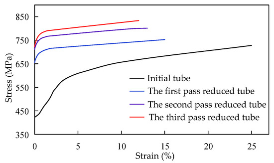
Figure 14.
Stress-strain curve.
The stress-strain relationship of the initial tube and the first, second, third pass reduced tube is respectively obtained by power function fitting as
The uniaxial tensile test results are shown in Table 4, and it can be found as follows:
Table 4.
Results of uniaxial tensile test.
- (1)
- The yield strength and ultimate tensile strength of each pass reduced tube are significantly higher than that of the initial tube. Both the yield strength and ultimate tensile strength are increased with the increase of reducing pass.
- (2)
- Both the elongation and section shrinkage are gradually decreased with the increase of reducing pass, which indicates that the plastic deformation ability of the reduced tube is gradually decreased, and axial cracking may occur.
4.4. FEA of PDR
The geometric models of tube with the wall thickness deviation T0 of 0 mm, 0.4 mm, 0.8 mm, 1.2 mm, 1.6 mm, 2.0 mm were established, respectively. The diameter d0, average wall thickness t0 and wave number n of the tube is 219 mm, 7.5 mm and 15, respectively. The software ABAQUS is used to simulate the four-pass PDR of wall thickness deviation tube. Since the tube and reducing dies are all axially symmetric structures, in order to facilitate calculation, the 1/4 finite element model was established, as shown in Figure 15.
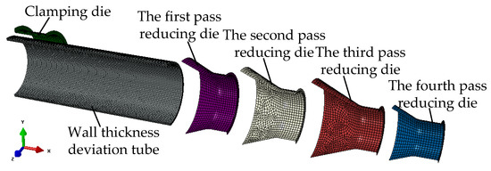
Figure 15.
Finite element model.
The stress-strain curves as shown in Figure 14 were used in the corresponding reducing pass. For the boundary conditions, symmetrical constraints were set on longitudinal center-section and middle cross-section of the tube, respectively. The middle area of the tube was fixed by upper and lower clamping die, the clamping die and reducing die of each pass were set as a rigid body, while the tube was set as a deformed body. The grid type of the tube is C3D8R, and the number of grid cells along the wall thickness direction is three. With the coulomb friction model, the rigid-flexible contact was established between the clamping die and the tube, and between the tube and each reducing die, respectively, and the dynamic friction coefficient of the contact was set as 0.15 and 0.10, respectively [24].
5. Results and Discussion
5.1. End of Reduced Tubes
After each pass PDR, the maximum and minimum wall thickness of the end were measured, and the end warpage (the difference between the radius of the end and sizing area) was measured. The maximum and minimum wall thickness of the sizing area were measured by transverse cutting at the distance of 50 mm from the end. The reduced tube with T0 = 1.2 and 0.4 are shown in Figure 16. It can be observed that the end of the reduced tube is warped. There is no obvious circumferential wrinkling at the end of the fourth pass reduced tube with T0 = 0.4. There is no obvious circumferential wrinkling at the end of the first pass reduced tube with T0 = 1.2, but obvious circumferential wrinkling on the inner wall at the end of the fourth pass, with the end unevenness of 2.47 mm and the sizing area unevenness of 0.84 mm.

Figure 16.
End warping and wrinkling of reduced tube. (a) The fourth pass reduced tube with T0 = 0.4; (b) the first pass reduced tube with T0 = 1.2; (c) the fourth pass reduced tube with T0 = 1.2.
Half of the sum of the maximum and minimum wall thicknesses is taken as the average wall thickness. The measurement results of diameter and wall thickness are shown in Table 5. It can be found that the average wall thickness of the end is less than that of the sizing area. While the diameter of the end is greater than that of the sizing area, and the latter is less than the inner diameter of the exit area of reducing die.
Table 5.
Geometric parameters of reduced tube (mm).
5.2. End Warpage
The end warpage of each pass reduced tube is shown in Table 6. It can be found that the end warpage is slowly increased with the increase of reducing pass (that is, the increase of reducing deformation), but the increase value is small, while the wall thickness deviation has little effect on the end warpage. The increased value of the end warpage of the experimental four-pass reduced tubes with T0 = 1.2 is 0.03 mm, 0.10 mm and 0.11 mm, respectively. While the end warpage of the experimental fourth pass reduced tube with T0 of 0.4 mm, 0.8 mm and 1.2 mm is 1.75 mm, 1.73 mm and 1.76 mm, respectively. The maximum difference between the FEA and EXP value of the end warpage is 7.34%, which is in the third pass reduced tube with T0 = 0.8.
Table 6.
End warpage of reduced tube (mm).
5.3. Unevenness
The end unevenness Td is greater than the initial unevenness T0, while the sizing area unevenness Ti is less than the T0, as shown in Figure 17. Further, it can be found that the Td is sharply increased with the increase of wall thickness deviation and reducing pass, while the Ti is slowly increased. For example, the Td of the experimental four-pass reduced tubes with T0= 1.2 is 1.39 mm, 1.69 mm, 1.90 mm and 2.47 mm, respectively, while the Ti is 0.69 mm, 0.73 mm, 0.80 mm and 0.84 mm, respectively. The maximum difference between the FEA and EXP value of unevenness is 11.91%, which is in the sizing area of the fourth pass reduced tube with T0 = 1.2.
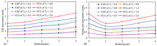
Figure 17.
Unevenness of reduced tube. (a) The end unevenness; (b) the sizing area unevenness.
5.4. Relative Unevenness of the End
The relative unevenness Kd of the end is sharply increased with the increase of wall thickness deviation and reducing pass, as shown in Figure 18. According to the judgment condition of the critical relative unevenness Kc of 1.10%, the Kd of the four-pass reduced tubes with T0 = 0.4 are all less than the Kc, which indicates that there is no circumferential wrinkling. The Kd of the experimental fourth pass reduced tube with T0 = 0.8 is 1.60% and the Kd of the second, third, fourth pass reduced tube with T0 = 1.2 is 1.15%, 1.61% and 2.57%, respectively, which are all larger than the Kc and indicate that the circumferential wrinkling at the end are all generated. The maximum difference between the FEA and EXP value of the Kd is 12.84%, which is in the first pass reduced tube with T0 = 0.8.

Figure 18.
Relative unevenness of the end.
From the above analysis, it can be found that the trend of the FEA and EXP results is the same, but there is a deviation in the value. The deviation value is mainly due to the difference between the finite element model and experimental conditions, such as the wall thickness deviation distribution, boundary condition setting and so on, and there are also some deviations in the measurement. However, the overall trend is reliable, which verifies the reliability of the geometric model of the tube with wall thickness deviation and the FEA results.
5.5. Generation and Development of End Wrinkling by the FEA
The stress and deformation of PDR with T0 = 1.2 was analyzed. The upper side of the tube is designated as the thin wall side, and the lower side is designated as the thick wall side. The measuring points A1, A, and A3, A4 were respectively selected on the outer and inner surface of the thin and thick wall side at the end. The measuring points B1, B2 and B3, B4 were respectively selected on the outer and inner surface of the thin and thick wall side at 25 mm away from the end. For the stress values, the “+” is signed for tensile stress, while the “−” is signed for compression stress.
5.5.1. Reducing Stage
During the reducing stage, the circumferential stress σθ is compressive, as shown in Figure 19, the σθ of the point B1 is −806.35 MPa. Moreover, the normal stress σn is compressive, the σn of the point B1 is −85.48 MPa. After the reducing stage deformation, the diameter of the end is decreased to 185.35 mm, the end wall thickness of the thin and thick wall side is increased to 7.42 mm and 8.65 mm, respectively, the end unevenness is 1.23 mm. While the diameter of the inner side of the end is decreased to 190.09 mm, the wall thickness of the thin and thick wall side is increased to 7.68 mm and 8.63 mm, respectively, and the unevenness is decreased to 0.95 mm.

Figure 19.
Reducing stage.
5.5.2. Bending Stage
After the end deformed in the bending stage, the circumferential stress of the point A1, A2, A3 and A4 is +464.76 MPa, +69.89 MPa, +435.95 MPa and +67.48 MPa, respectively, as shown in Figure 20. The axial stress of the outer surface point B1 and B3 is −564.81 MPa and −595.18 MPa, respectively. The axial stress of the thin wall side point B2 is +471.47 MPa, which is larger than the thick wall side point B4 of +442.55 MPa. The results are in good agreement with the theoretical analysis.
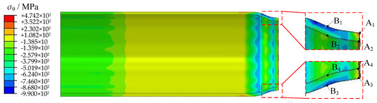
Figure 20.
Bending stage.
The end wall thickness of the thin and thick wall side is decreased from 7.42 mm and 8.65 mm to 7.35 mm and 8.63 mm, respectively. The thinning of the thin wall side is 0.07 mm, which is greater than the thick wall side of 0.02 mm, and the end unevenness is increased to 1.28 mm. While the diameter of the inner side of the end is decreased to 187.56 mm, the wall thickness of the thin and thick wall side is increased to 7.92 mm and 8.69 mm, respectively, and the unevenness is decreased to 0.77 mm.
5.5.3. Warping Stage
In warping stage, the end diameter is expanded to 190.36 mm. The circumferential stress σθ of the thin wall side point A1 is +643.36 MPa, which is greater than the thick wall side point A4 of +639.79 MPa. The σθ of the thin wall side point A2 is +625.74 MPa, which is greater than the thick wall side point A3 of +605.49 MPa. The FEA results are in good agreement with the theoretical analysis. There is the shear stress τρn in the end warping area, as shown in Figure 21; the maximum shear stress of the thin and thick wall side is 81.02 MPa and 75.13 MPa, respectively.
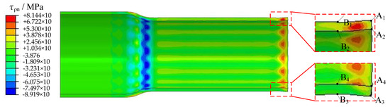
Figure 21.
Warping stage.
The end wall thickness of the thin and thick wall side is decreased from 7.35 mm and 8.63 mm to 7.28 mm and 8.58 mm, respectively. The thinning of the thin wall side is 0.07 mm, which is greater than the thick wall side of 0.05 mm. Moreover, the end unevenness is further increased to 1.30 mm. While the inner side of the end is no longer warped, and the unevenness is no longer changed as well.
5.5.4. Multi-Pass Diameter-Reducing
The FEA results of the reduced tubes were mirrored for convenient observation, as shown in Figure 22. It can be observed that the end unevenness Td is gradually increased with the increase of reducing pass, which is consistent with the trend of the EXP results. For each pass reduced tube, the Td is 1.30 mm, 1.63 mm, 1.77 mm and 2.21 mm, respectively, the sizing area unevenness is 0.77 mm, 0.80 mm, 0.86 mm and 0.94 mm, respectively, and the relative unevenness of the end is 0.76%, 1.13%, 1.56%, 2.34%, respectively. In addition, circumferential wrinkles are generated on the inner wall at the end warping area in the second, third and fourth pass.

Figure 22.
Four-pass reduced tubes of T0 = 1.2. (a) The first pass; (b) the second pass; (c) the third pass; (d) the fourth pass.
5.6. Evolution Law of Unevenness
The end unevenness Td is greater than the initial unevenness T0, while the sizing area unevenness Ti is less than the T0, as show in Figure 23. It can be found that the Td is gradually increased from the reducing stage to warping stage. While the Ti is gradually decreased from the reducing stage to bending stage, and no longer changed in the warping stage.
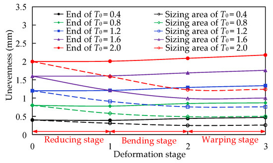
Figure 23.
Evolution process of unevenness.
5.7. Circumferential Residual Stress of the End
In the thin wall side, the average value of the sum of circumferential residual tensile stress of each depth layer at the end is taken as the circumferential residual tensile stress σθ. The σθ of each pass reduced tube is shown in Figure 24. It can be observed that the σθ is increased with the increase of reducing pass, while the wall thickness deviation has little effect on the σθ. When the σθ is greater than the ultimate tensile strength, the end may be cracked axially.
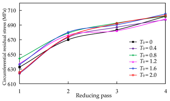
Figure 24.
Circumferential residual stress of the end.
6. Control Method
6.1. PPDR Process
From the above analysis, it can be known that the end warping and wrinkling are mainly caused by the bending deformation in the rounded corner area of reducing die, which results in the diameter of sizing area being less than that of the end and the reducing die exit area and leads to the circumferential residual tensile stress at the end. In order to control the end circumferential wrinkling and axial cracking, it is necessary to decrease the bending deformation, so as to decrease the deformation difference between the inner and outer side metals, and then decrease the end warping.
The PPDR process is proposed based on the above control ideas. The mandrel is pushed into the tube inside before reducing. During the reducing die moves inward from the tube end with the speed V0 under the pushing force Fr, the mandrel moves from the tube inside to outside with the speed Vm under the pulling force Fm. Moreover, the pulling speed Vm is greater than the tube elongation speed V1, as shown in Figure 25.

Figure 25.
Process of PPDR.
After the tube deformed in the reducing stage, the inner surface of the tube is in contact with the outer surface of the mandrel, and the tube is subjected to the normal pressure Fn2 and the tangential friction force Ft2. The direction of the Ft2 is opposite to the speed V0 of the reducing die, which is equivalent to the drawing force exerted on the tube inner wall. Compared with the fixed mandrel, the possibility of axial instability in the tube middle force transfer area is effectively decreased by the pulling mandrel. Under the combined action of the reducing die and mandrel, the bending deformation is decreased, the deformation difference between the inner and outer side metals is decreased and then the end warpage and unevenness are decreased.
6.2. FEA of PPDR
6.2.1. Finite Element Model
For the initial tube with T0 = 1.2, the software ABAQUS is used to simulate the four-pass PPDR. Based on the axial stability of the tube force transfer area and the end without cracking [25], the diameter of each pass mandrel is respectively determined as 173.8 mm, 144.8 mm, 118.6 mm and 93.7 mm. The finite element model of PPDR is shown in Figure 26. The setting of tube, clamping die and reducing die is the same as that of the PDR finite element model, and the mandrel is set as rigid body, the friction coefficient between mandrel and tube is set as 0.15, the pushing speed of reducing die is 10 mm/s and the pulling speed of mandrel is 12 mm/s.
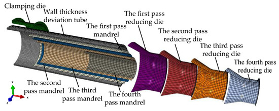
Figure 26.
Finite element model.
6.2.2. FEA Results and Discussions
- (1)
- End warping
A comparison of the end warpage and sizing area diameters between PDR and PPDR is shown in Table 7. It can be found that the end warpage is greatly decreased by the PPDR, while the sizing area diameter is increased, which indicates that the deformation difference in the bending stage is decreased. In addition, the end warpage of each pass PPDR is decreased by 85.89%, 86.83%, 82.76% and 82.07%, respectively, and the forming quality of reduced tube is better.
Table 7.
Comparison of warpage and diameter (mm).
- (2)
- Circumferential residual tensile stress of the end
Comparison of the circumferential residual tensile stress at end in the first pass bet- ween PDR and PPDR is shown in Figure 27. The comparison results were as follows:

Figure 27.
Circumferential residual stress of end.
- (1)
- The circumferential residual tensile stress of the end can be effectively controlled by the PPDR. The circumferential residual stress of the outer and inner surface at the end is tensile and compressive, respectively.
- (2)
- The circumferential residual tensile stress can be greatly decreased by the PPDR. In the first pass, the circumferential residual tensile stress at the outer surface of end is decreased by 71.67%, which effectively eliminates the risk of axial cracking at end.
- (3)
- End unevenness
Comparison of end unevenness and relative unevenness between PDR and PPDR is shown in Table 8. It can be found that the end unevenness and relative unevenness can be greatly decreased by the PPDR. The end unevenness of each pass PPDR is decreased by 65.37%, 79.14%, 81.92%, 84.16%, respectively. The end’s relative unevenness is less than the initial and critical relative unevenness, which effectively controls the circumferential wrinkling at end.
Table 8.
Comparison of unevenness.
6.3. Experimental Verification
The initial tube with T0 = 1.2 was selected to carry out the four-pass PPDR on the THP63-200/300/100 × 2 hydraulic press. The reducing die of each pass is the same as the PDR, and the mandrel diameter of each pass is the same as the FEA.
The dies of PPDR are shown in Figure 28. The left and right reducing die are respectively fixed on the left and right support cylinder, which are respectively connected with the left and right slider of hydraulic press. The left and right mandrel are respectively connected with the left and right central cylinder of hydraulic press. The upper clamping die is fixed on the upper die base, which is connected with the upper slider of hydraulic press. The lower clamping die is fixed on the lower die base, which is fixed on the working platform of hydraulic press.
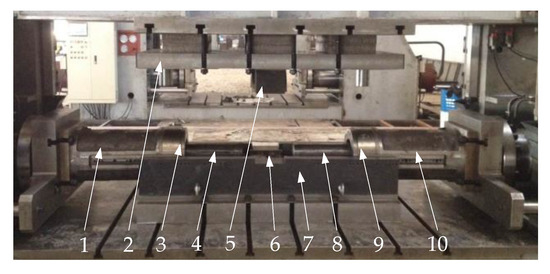
Figure 28.
PPDR dies. 1. Left support cylinder; 2. Upper die base; 3. Left reducing die; 4. Left mandrel; 5. Upper clamping die; 6. Lower clamping die; 7. Lower die base; 8. Right mandrel; 9. Right reducing die; 10. Right support cylinder.
Before diameter-reducing, the upper slider of hydraulic press drives the upper die base and upper clamping die to move downward to clamp the middle area of the tube, and the left and right mandrel are respectively pushed into the tube inside by the left and right central cylinder. During diameter-reducing, the left and right reducing die are respectively pushed inward from the tube end with the speed 10 mm/s by the left and right slider, while the left and right mandrel are respectively pulled from the tube inside to outside with the speed 12 mm/s by the left and right central cylinder. For the convenience of measurement and observation, the reduced tube is cut along the 1/4 longitudinal section, as shown in Figure 29. It can be observed that there is no obvious warping and circumferential wrinkling at the end.
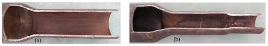
Figure 29.
Reduced tube of PPDR. (a) The first pass; (b) the fourth pass.
Comparison of the EXP and FEA value of end warpage and unevenness between PDR and PPDR is shown in Table 9. The comparison results showed as follows:
Table 9.
Comparison results (mm).
- (1)
- The end warpage can be greatly decreased by the PPDR. Compared with the EXP results of PDR, the end warpage of each pass PPDR tube is decreased by 71.71%, 76.77%, 78.66% and 76.70%, respectively. The FEA results of the PPDR are in good agreement with the EXP results.
- (2)
- The end unevenness can be effectively decreased by the PPDR. Compared with the EXP results of the PDR, the end unevenness of each pass PPDR tube is decreased by 53.24%, 68.05%, 73.68% and 80.16%, respectively. Furthermore, the FEA results of the PPDR are consistent with the EXP results.
The above research results indicate that the end warping and circumferential wrinkling can be greatly controlled by the PPDR, the risk of axial cracking at end can be effectively eliminated and the forming quality of reduced tube can be improved.
7. Conclusions
In this paper, the mechanical model of PDR and the geometric model of the tube with the wall thickness deviation were established to reveal the axial cracking and circumferential wrinkling mechanism of PDR. The experiments and simulations were developed to validate the theoretical analysis and reveal the influence of process parameters on the wrinkling and cracking. In order to solve the above problems, the method of PPDR was proposed. The main conclusions could be summarized as follows:
- (1)
- The Equation of circumferential residual stress at end was deduced from the warping deformation and shear stress, it reveals that the circumferential residual stress in the end warping area from the inner to outer surface is tensile. The circumferential residual tensile stress of the thin wall side is greater than that of the thick wall side.
- (2)
- The generation mechanism of circumferential wrinkling on the inner wall at the end was revealed. The geometric model of tube with wall thickness deviation was proposed, in which the outer surface shape is a circle and the inner surface shape is a periodic sinusoidal variation. On the base of it, the generation and development of circumferential wrinkling at the end was demonstrated and the evolution law of unevenness was revealed.
- (3)
- The end unevenness is greater than the initial unevenness, while the sizing area unevenness is less than it. The end unevenness and relative unevenness are sharply increased with the increase of wall thickness deviation and reducing pass, while the sizing area unevenness is increased slowly. The end warpage and circumferential residual tensile stress at end are increased slowly with the increase of reducing pass, while the wall thickness deviation has little effect on them.
- (4)
- The pushing-pulling diameter-reducing process was proposed to control the wrinkling and cracking. The simulation and experimental verification results showed that the sizing area diameter is increased, the deformation difference in bending stage is decreased, then the end warpage, unevenness and circumferential residual tensile stress of the end are all greatly decreased, the risk of axial cracking and circumferential wrinkling is eliminated and the forming quality of the reduced tube is improved.
Author Contributions
Conceptualization, L.W.; methodology, H.L.; software, X.W. and Q.T.; validation, H.L. and X.W.; investigation, H.L.; data curation, Q.T.; writing—original draft preparation, H.L.; writing—review and editing, L.W. and H.L.; funding acquisition, L.W. All authors have read and agreed to the published version of the manuscript.
Funding
This research was funded by the Major Scientific and Technological Achievements Transformation Project of Hebei Province (Grant No. 20282202Z) and the Natural Science Foundation of Hebei Province (Grant No. E2016203352).
Conflicts of Interest
The authors declare no conflict of interest.
Nomenclature
| PDR | Pushing diameter-reducing |
| PPDR | Pushing-pulling diameter-reducing |
| L0 | Length of the initial tube (mm) |
| d0 | Outer diameter of the initial tube (mm) |
| tm0 | The maximum wall thickness of the initial tube (mm) |
| tn0 | The minimum wall thickness of the initial tube (mm) |
| t0 | Average wall thickness of the initial tube (mm) |
| Tm | The positive deviation (mm) |
| Tn | The negative deviation (mm) |
| T0 | The initial wall thickness deviation (mm) |
| θn | Period angle (°) |
| n | Wave number |
| tm | The maximum wall thickness (mm) |
| tn | The minimum wall thickness (mm) |
| T | Unevenness (mm) |
| K | Relative unevenness (%) |
| di | Average inner diameter of tube (mm) |
| Kc | Critical relative unevenness (%) |
| Tx | The maximum allowable wall thickness deviation (mm) |
| di0 | Inner diameter of initial tube (mm) |
| α | Half-cone angle of reducing die (°) |
| dm | Inner diameter of the exit area (mm) |
| R | Rounded corner radius of reducing die (mm) |
| Rm0 | Intermediate layer radius of the thick wall side (mm) |
| Rn0 | Intermediate layer radius of the thin wall side (mm) |
| Rm1 | Intermediate layer radius of the thick wall side in reducing stage (mm) |
| Rn1 | Intermediate layer radius of the thin wall side in reducing stage (mm) |
| tm1 | Wall thickness of the thick wall side in reducing stage (mm) |
| tn1 | Wall thickness of the thin wall side in reducing stage (mm) |
| Rm2 | Intermediate layer radius of the thick wall side in bending stage (mm) |
| Rn2 | Intermediate layer radius of the thin wall side in bending stage (mm) |
| tm2 | Wall thickness of the thick wall side in bending stage (mm) |
| tn2 | Wall thickness of the thin wall side in bending stage (mm) |
| d02 | Outer diameter of the tube end in bending stage (mm) |
| dl | Axial length of the bending element body (mm) |
| dy | Circumferential length of the bending element body (mm) |
| te | Wall thickness of the bending element body (mm) |
| σρe1 | Axial equivalent compressive stress on the outside of intermediate layer (MPa) |
| σρe2 | Axial equivalent tensile stress on the inside of intermediate layer (MPa) |
| dM | Torque on the right surface of the bending element body (N·m) |
| τρn | Shear stress (MPa) |
| Rm3 | Intermediate layer radius of the thick wall side in warping stage (mm) |
| Rn3 | Intermediate layer radius of the thin wall side in warping stage (mm) |
| tm3 | Wall thickness of the thick wall side in warping stage (mm) |
| tn3 | Wall thickness of the thin wall side in warping stage (mm) |
| rρ | Axial curvature radius of the upper side of warping element body (mm) |
| β | Included angle of the upper side of warping element body (°) |
| σρo | Axial tensile stress on the outer layer of warping element body (MPa) |
| σρi | Axial compressive stress on the inner layer of warping element body (MPa) |
| σθm | Circumferential residual stress of the thick wall side (MPa) |
| σθn | Circumferential residua stress of the thin wall side (MPa) |
| σθ | Circumferential residual stress (MPa) |
| l0 | Gauge length (mm) |
| lt | Length of tensile specimen (mm) |
| Td | End unevenness (mm) |
| Ti | Sizing area unevenness (mm) |
| Kd | Relative unevenness of the end (%) |
| σn | Normal stress (MPa) |
| V0 | Speed of reducing die (mm/s) |
| Fr | Pushing force of reducing die (KN) |
| Vm | Speed of mandrel (mm/s) |
| Fm | Pulling force of mandrel (KN) |
| V1 | Speed of tube elongation (mm/s) |
| Fn2 | Normal pressure (KN) |
| Ft2 | Tangential friction force (KN) |
References
- Fisher, W.P.; Ddy, A.J. A Study of the factors controlling the tube-sinking process for polymer materials. J. Mater. Process. Technol. 1997, 68, 156–162. [Google Scholar] [CrossRef]
- Celentano, D.J.; Rosales, D.A.; Jorge, A.P. Simulation and experimental validation of tube sinking drawing processes. Mater. Manuf. Process. 2011, 26, 770–780. [Google Scholar] [CrossRef]
- Almeida, B.P.P.; Alves, M.L.; Rosa, P.A.R.; Brito, A.G.; Martins, P.A.F. Expansion and reduction of thin-walled tubes using a die: Experimental and theoretical investigation. Int. J. Mach. Tools Manuf. 2006, 46, 1643–1652. [Google Scholar] [CrossRef]
- Tangsri, T.; Norasethasopon, S. 3D FEM validation of ultra-small inner spiral ribbed copper tube using the tube sinking method. Int. J. Adv. Manuf. Technol. 2015, 81, 1949–1959. [Google Scholar] [CrossRef]
- Salehi, J.; Rezaeian, A.; Toroghinejad, M.R. Fabrication and characterization of a bimetallic Al/Cu tube using the tube sinking process. Int. J. Adv. Manuf. Technol. 2018, 96, 153–159. [Google Scholar] [CrossRef]
- Rumiński, M.; Łuksza, J.; Kusiak, J.; Paćko, M. Analysis of the effect of die shape on the distribution of mechanical properties and strain field in the tube sinking process. J. Mater. Process. Technol. 1998, 80–81, 683–689. [Google Scholar] [CrossRef]
- Lu, Y.H. Study of preform and loading rate in the tube nosing process by spherical die. Comput. Methods Appl. Mech. Eng. 2005, 194, 2839–2858. [Google Scholar] [CrossRef]
- Zhao, D.W.; Du, H.J.; Wang, G.J.; Liu, X.H.; Wang, G.D. An analytical solution for tube sinking by strain rate vector inner-product integration. J. Mater. Process. Technol. 2009, 209, 408–415. [Google Scholar] [CrossRef]
- Ogbeyemi, A.; Okoh, I.; Imuero, O.; Ibhadode, O.; Akpobi, J. Load prediction on metal forming process (tube sinking) using finite element method. J. Adv. Manuf. Technol. 2021, 114, 2961–2973. [Google Scholar] [CrossRef]
- Sadok, L.; Kusiak, J.; Packo, M.; Rumiński, M. State of strain in the tube sinking process. J. Mater. Process. Technol. 1996, 60, 161–166. [Google Scholar] [CrossRef]
- Hirsch, T.K.; Silva, R.A.; Menezes, N.R. Characterization of local residual stress inhomogeneities in combined wire drawing processes of AISI 1045 steel bars. Int. J. Adv. Manuf. Technol. 2014, 70, 661–668. [Google Scholar] [CrossRef]
- Vollert, F.; Luchiner, M.; Schuster, S.; Simon, N.; Gibmeier, J.; Kern, K.; Schreiner, M.; Tillmann, W. Experimental and numerical analyses of residual stresses induced by tube drawing. J. Strain. Anal. Eng. 2018, 53, 364–375. [Google Scholar] [CrossRef]
- Gattmah, J.; Ozturk, F.; Orhan, S. Experimental and finite element analysis of residual stresses in cold tube drawing process with a fixed mandrel for AISI 1010 steel tube. Int. J. Adv. Manuf. Technol. 2017, 93, 1229–1241. [Google Scholar] [CrossRef]
- Kishimoto, T.; Sakaguchi, H.; Suematsu, S.; Tashima, K.; Kajino, S.; Gondo, S.; Suzuki, S. Deformation behavior causing excessive thinning of outer diameter of micro metal tubes in hollow sinking. Metals 2020, 10, 1315. [Google Scholar] [CrossRef]
- Liu, H.; Wang, L.D.; Wang, X.D.; Liu, C. Study on the residual stress of large deformation free pushing diameter-reducing tube blanks. China Mech. Eng. 2021, 32, 1354–1360. [Google Scholar]
- Liu, G.H.; Guo, Y.Q.; Jiang, Z. Influence of heating models on necking deformation during tube extrusion process. Adv. Mater. Res. 2011, 189–193, 1778–1781. [Google Scholar] [CrossRef]
- Teng, H.; Teng, B. An optiming process design for sinking with the thin-wall cylindrical cup. Appl. Mech. Mater. 2014, 456, 22–27. [Google Scholar] [CrossRef]
- Zhao, C.C.; Han, Z.J.; Du, B.; Zhang, X.; Xie, J. Wrinkling prediction of aluminum alloy tubes during reduced diameter compression forming. Int. J. Adv. Manuf. Technol. 2020, 106, 65–75. [Google Scholar] [CrossRef]
- Zhang, X.; Zhao, C.C.; Du, B.; Li, H.; Han, Z.J.; Song, P.F. Numerical simulation on wrinkling instability of tube outer pressure compression. Chin. J. Nonferrous Metals. 2020, 307, 1855–1865. [Google Scholar]
- Shirayori, A.; Fuchizawa, S.; Ishigure, H.; Narazaki, M. Deformation behavior of tubes with thickness deviation in circumferential direction during hydraulic free bulging. J. Mater. Process. Technol. 2003, 139, 58–63. [Google Scholar] [CrossRef]
- He, Z.; Wang, Z.; Lin, Y.; Zhu, H.; Yuan, S. A modified Marciniak-Kuczynski model for determining the forming limit of thin walled tube extruded with initial eccentricity. Int. J. Mech. Sci. 2018, 151, 715–723. [Google Scholar] [CrossRef]
- Wang, L.D.; Cui, Y.P.; Yang, D.F. Study of bulging-pressing compound-deforming automobile axle housing with a common press. Appl. Mech. Mater. 2012, 217, 1972–1977. [Google Scholar] [CrossRef]
- GB/T 8162-2018. Seamless Steel Tubes for Structural Purposes; Standards Press of China: Beijing, China, 2018. [Google Scholar]
- Syahrulbil, S.; Hariz, M.; Hamid, M.; Baker, A. Friction characteristic of mineral oil containing palm fatty acid distillate using four ball tribo-tester. J. Procedia Eng. 2013, 68, 166–171. [Google Scholar] [CrossRef][Green Version]
- Wang, L.D.; Liu, C.; Liu, H.; Wang, X.; Wang, Z. Effects of mandrel diameters on large deformation pushing-pulling necking. China Mech. Eng. 2018, 29, 2131–2136. [Google Scholar]


Publisher’s Note: MDPI stays neutral with regard to jurisdictional claims in published maps and institutional affiliations. |
© 2021 by the authors. Licensee MDPI, Basel, Switzerland. This article is an open access article distributed under the terms and conditions of the Creative Commons Attribution (CC BY) license (https://creativecommons.org/licenses/by/4.0/).